Transcription
ENGLISHESS design and installationmanualRev 04 03/2022
ESS design and installation manualTable of Contents1. ESS Introduction & features . 41.1. Let's look at the following example-installations: . 61.2. Components . 62. System design . 82.1. PV . 82.1.1. MPPT Solar Charger and/or Grid-tie inverter . 82.1.2. Feed-in or no Feed-in . 82.1.3. Fronius Zero Feed-in . 82.1.4. MPPT Solar Chargers . 82.1.5. Grid-tie inverter in parallel or on AC out? . 82.2. Battery bank capacity . 92.3. Inverter/charger size . 92.4. Anti-islanding . 93. Installation . 104. Configuration . 114.1. Update to latest firmware . 114.2. Multi/Quattro and ESS Assistant . 114.3. GX device - ESS Settings . 114.3.1. Mode . 124.3.2. Grid meter installed . 124.3.3. Inverter AC output in use . 134.3.4. Feed-in excess solar charger power . 134.3.5. Phase compensation . 134.3.6. Minimum Discharge SoC (unless grid fails) . 134.3.7. Actual state of charge limit . 134.3.8. BatteryLife state . 134.3.9. Limit charge power . 134.3.10. Limit inverter power . 134.3.11. Zero or limited feed-in . 134.3.12. Grid setpoint . 144.4. GX device - Scheduled Charging . 144.4.1. Introduction . 144.4.2. Configuration . 144.4.3. Stop charge on SoC . 154.4.4. Frequently asked questions . 154.5. GX device - Other settings . 164.5.1. Settings - System setup - AC Input types . 164.5.2. Settings - Generator start/stop . 164.6. MPPT Solar Charger . 165. Commissioning . 176. Controlling depth of discharge . 186.1. Overview . 186.2. BatteryLife . 186.3. Dynamic Cut-off . 196.4. Sustain Mode . 206.5. ESS Battery Status Reason Code Numbers . 207. Multiphase regulation - further information . 227.1. Introduction . 227.2. Single phase ESS in a three-phase system . 227.3. Three-phase ESS . 228. Comparison to Hub Assistants . 248.1. Hub-1 Assistant - ESS Assistant . 248.2. Hub-2 (v3) Assistant - ESS Assistant . 248.3. Hub-4 Assistant - ESS Assistant . 249. ESS Quick Installation Guide . 259.1. Step 1 - Understand how a Victron Energy ESS system works . 259.2. Step 2 - Decide what type of ESS . 259.3. Step 3 - Select the system hardware . 269.4. Step 4 - Install all equipment . 279.5. Step 5 - Update firmware of all equipment . 279.6. Step 6 - Set up parallel and/or 3 phase inverter/chargers . 279.7. Step 7 - Configure the inverter/charger(s) . 279.8. Step 8 - Connect all communication cables . 289.9. Step 9 - Make the GX device settings . 289.10. Step 10 - Set up VRM . 289.11. Step 11 - Commissioning . 282
ESS design and installation manual10. FAQ .10.1. Q1: Is power from MPPT used to power the loads when feedback is disabled? .10.2. Q2: I've enabled optimize mode, but do not see grid-power being used to charge the battery .10.3. Q3: Even when the battery is full, the system is still connected to AC-in .10.4. Q4: Why is the VE.Bus state in pass-through? .10.5. Q5: How can I suppress low battery warnings? .10.6. Q6: Optimize mode, no feed-in: The AC Input current fluctuates wildly - sometimes even going negative .why is this? .10.7. Q7: How do the charge states work in ESS? .10.8. Q8: My system switches off in overload - why is this? .10.9. Q9: Why are my loads powered by the grid instead of battery or solar? .10.10. Q10:Why does the system refuse to discharge my battery? .10.11. Q11: My battery is first discharging, and then charged every night? .10.12. Q12: What is auto-recharge? .10.13. Q13: Can I use ESS in a vehicle or a boat? .10.14. Q14: Why does my split and 3 phase ESS VRM data not match my billing? .11. Troubleshooting .329292929292930303030313131313132
ESS design and installation manual1. ESS Introduction & featuresWhat is ESS?An Energy Storage System (ESS) is a specific type of power system that integrates a power grid connection with a VictronInverter/Charger, GX device and battery system. It stores solar energy into your battery during the day, for use later on when thesun stops shining.It allows for time shifting power, charging from solar, providing grid support, and exporting power back to the grid.When an ESS system is able to produce more power than it can use and store, it can sell the surplus to the grid; and when it hasinsufficient energy or power, it automatically buys it from from the grid.In the ESS system, there must at least be one inverter/charger and also a GX device such as: Cerbo GX Venus GXOther components can be added when needed, see chapter 2. [8]When is it appropriate to use ESS?Use ESS in a self-consumption system; a backup system with solar, or a mixture of both: For example you can use 30% of thebattery capacity for self-consumption, and keep the other 70% available as a backup in the event of utility grid failure.Optimizing self-consumption:When there is more PV power than is required to run loads, the excess PV energy is stored in the battery. That stored energy isthen used to power the loads at times when there is a shortage of PV power.The percentage of battery capacity used for self-consumption is configurable. When utility grid failure is extremely rare it could beset to 100%. In locations where grid failure is common - or even a daily occurrence - you might choose to use just 20% of batterycapacity and save 80% for the next grid failure. African countries for example.4
ESS design and installation manualKeep batteries 100% charged:ESS can also be configured to keep the batteries fully charged. Utility grid failure is then the only time battery power is used - as abackup. Once the grid is restored, the batteries will be recharged either from the grid or from solar panels - when available.ESS in a system with a generatorConfiguring ESS in a system which uses a diesel generator as backup - for extended mains failures - can be achieved. Grid codeand Loss of Mains configuration will need special attention, see here.And on the GX device, select 'Generator' as the AC Input type in the Settings System setup menu. The system will then enablegenerator charging; ensure that the generator is properly loaded, and will be automatically switched-off as soon as parametersare met.When not to use ESS Off-grid systems - either with or without generator.Marine systems.Automotive systems.Inverter priority, also known as 'Intentional islanding“ or 'Ignore AC' input systems.With and without grid-meterESS can be used both with an external grid-meter, or without one.Where there is a grid-meter; either a full or partial grid-parallel system can be configured to run alongside.Where there is no grid-meter; all loads are connected to AC-out. And where there is a PV Inverter present, that is also connectedto AC out.Optional feed-in of MPPT Solar charger powerPower from an MPPT can be fed back to the grid. Enabled/disabled by a user setting on the CCGX: Settings ESS.Fronius Zero feed-in optionBy using the Power Reduction feature in Fronius grid-tie inverters, the ESS system can automatically reduce the output of theinstalled PV Inverters as soon as feed-back is detected; without switching and frequency shifting.It is not possible to combine ESS with the Fronius Smart Meter - but it's not necessary either, as ESS already has metering.With ESS, it is not possible to disable feed-in a system with other brands of grid-tie inverters. See Chapter 2.1.2 [8] for moreinformation.ESS Training5
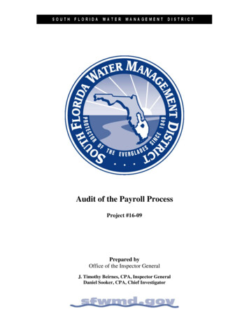
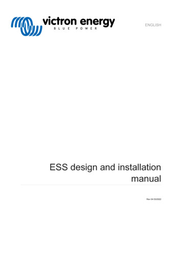
ESS design and installation manual ESS Webinar 2016-12-19 Youtube (EN)ESS Webinar 2016-12-19 Youtube (DE)ESS Webinar 2016-12-19 Youtube (ES)ESS Webinar 2016-12-19 PPTEnergy Storage System introduction, examples and diagramsA separate document that provides further introductory information, overviews, and system examples is available to downloadhere.Advanced control optionsSee ESS mode 2 and 3.1.1. Let's look at the following example-installations: Residential scale Energy Storage System with MPPT Solar Charger Retrofitting an existing Grid-tie inverter installation System with Generator backup (using the auto genset start/stop feature in CCGX)Backup system with SolarAll loads are wired on the AC output of the inverter/charger. The ESS mode is configured to 'Keep batteries charged'.When using a grid-tie inverter, it is connected to the AC output as well.When grid power is available the battery will be charged with power from both the grid and the PV. Loads are powered from PVwhen that power-source is available.Feed-in is optional, and can be enabled or disabled depending on local regulations.1.2. ComponentsInverter/chargerThe Energy Storage system, uses a Multi or Quattro bidirectional inverter/charger as its main component.Note that ESS can only be installed on Multis and Quattros which feature the 2nd generation microprocessor (26 or 27). All newsystems shipped have 2nd generation chips.GX deviceThe system is managed by the Color Control GX (CCGX), which also provides extensive monitoring, both locally and remotely viaour VRM Portal and the VRM App.BatteryVictron Lithium batteries ttery-12-8v ttery-24v-180ahThird-party battery compatibilityPlease see this list of third-party batteries with which Victron equipment is ery compatibility:startLead batteries: OPzS and OPzVThe relatively high internal-resistance of these types of batteries should be taken in to account when designing a system whichuses them.Lead batteries: AGM / GELNote that the use of standard AGM and GEL batteries is not recommended for installations designed to cycle the battery bankevery day.Battery MonitorIn most situations, it is not necessary to install a battery monitor: Lithium batteries with canbus connection (BYD B-Box, Pylon, LG Resu and others) already have a built-in battery monitor.Adding another will only set up a conflict. Always use the canbus connection to provide battery status/state-of-charge data forthese batteries.6
ESS design and installation manual Redflow ZBM / ZCell zinc-bromide flow batteries with the ZCell BMS also support the same canbus protocol. This is thepreferred integration approach for these batteries. The built-in battery monitor of the Multi Inverter/Charger can be used to provide data where installed batteries do not have amonitor built-in. The advantage here is that in an ESS system the charge currents from MPPT Solar Chargers will also be takeninto account.The only situation where an external battery monitor is required is when a system using a no-monitor battery type also hasadditional power sources: for example a DC wind generator. (No monitor battery types include lead batteries, for example,or Victron 12.8V lithium batteries.)Where an additional battery monitor is necessary, use one of these: BMV-700 Lynx Shunt VE.CanDetailed information is available in the CCGX manual chapter 5.2.Grid Meter (optional)For a full or partial grid-parallel installation an Energy Meter can be installed in the main distribution panel between the grid andthe installation.A grid meter is not required where there are no AC renewable-energy source(s) and also no AC load(s) present on thethe input side of the Multi/Quattro system (i.e. where all such sources and loads are on the output side of the Multi/Quattrosystem).If there is any AC renewable energy source or any AC load between the grid connection point and the input side of theMulti/Quattro system, incorrect results will be calculated and recorded by the GX unless a grid meter is installed and enabled.In particular, without a grid meter: When renewable energy is being provided on the input side, the grid value will be wrong (too low/negative); and The AC Load value shown will be too low (and will show zero where there is a surplus of renewable energy).Both issues are resolved by installing a grid meter.Click here for more information about the configuration of grid meters.PV (optional)ESS can work with both Grid-tie PV inverters and/or MPPT Solar Chargers. (A mix of both is also possible.)When using Grid-tie PV Inverters we recommend monitoring is performed using the CCGX. See CCGX manual for the options.ESS can also be operated without PV. This is typical for virtual power plants, where the installation is part of a cluster of smallstorage systems - supplying energy to the grid during peak demand.7
ESS design and installation manual2. System design2.1. PV2.1.1. MPPT Solar Charger and/or Grid-tie inverterESS can work with either an MPPT Solar Charger or a grid-tie inverter, and a mix of both.Generally speaking the MPPT Solar Charger will be more effective than a grid-tie inverter in a small system. The reason for this isthat an MPPT Solar Charger is up to 99% efficient whereas the PV energy coming from a grid-tie inverter is first converted fromDC to AC, and then back from AC to DC, causing losses up to 20 or 30%. This will be even more noticeable when the energyconsumption takes place mainly in the mornings and the evenings.When most of the energy consumption takes place during the day - say in an office with air-conditioning - a grid-tie inverter will bemore efficient. After (very efficient) conversion to AC, the PV energy is used directly by the air-conditioning unit.In the case of 'no Feed-in' consider using an MPPT Solar Charger - or otherwise a Fronius PV Inverter, and then use the ZeroFeed-in function. This will lead to a much more stable system.2.1.2. Feed-in or no Feed-inThe rules around Feed-in differ all around the world. In various countries:1. Energy can be sold back to the grid- or to reduce the electricity bill by running in reverse.2. Feed-in is allowed, but not rewarded: All energy being fed back is lost in the sense that the utility provider will not pay for youit. It is, however, an ecologically-sound power-contribution3. Feed-in is absolutely not tolerated - even for a few seconds: there are certain prepaid meters in South-Africa that willdisconnect from the grid when they detect Feed-in.4. Feeding-in results in inflated bills because the electricity meter can only count in one direction - up. Every kWh fed-back to thegrid is erroneously counted as energy used, and will be charged for.Feed-inFeed-in of PV power via an MPPT Solar Charger can be enabled or disabled in the Energy Storage Systems menu on the CCGX.Note that when disabled, the PV power will still be available to power AC loads.Feed-in of PV connected to grid-tie inverters occurs automatically. There are no settings or special design considerations to beconsidered whether connected on the input and/or output of the inverter/charger.No feed-inFeed-in of PV power via an MPPT Solar Charger can be enabled or disabled in the Energy Storage Systems menu on the CCGX.For grid-tie inverters, the only option is to use a Fronius grid-tie inverter and use the Fronius Zero Feed-in function. Seechapter 2.1.3 [8].Using other brands of grid-tie inverters in a No-feed-in system is not recommended. With ESS it is not possible to prevent feed-inwhere other brands are installed. And using the Hub-2 Assistant as an alternative method leads to a less-than-perfect installation.There can be problems with flickering lights - or even a whole-system shut-down, through overload, when a large load is switchedon or off.2.1.3. Fronius Zero Feed-inFor Fronius grid-tie inverters ESS has a special feature: Zero feed-in.With the Zero feed-in option enabled, the ESS system will continuously monitor and actively control the output power of theFronius grid-tie inverter. See chapter 4.3.11 [13] for detailed requirements and settings.2.1.4. MPPT Solar ChargersAll Victron MPPT solar chargers can be used: both the models with a VE.Direct port as well as the models with a VE.Can port.2.1.5. Grid-tie inverter in parallel or on AC out?There are two options when connecting the grid-tie inverter: in parallel with the Multi or Quattro. on the AC out.When connected on the AC out, the factor 1.0 rule must be adhered to. There are no exceptions to this. Also use the factor1.0 rule in countries where the utility grid rarely fails; and also when connecting a Fronius grid-tie inverter on the AC out, andemploying 'Zero feed-in'.8
ESS design and installation manual2.2. Battery bank capacityIn a grid-parallel system, the size of the battery bank has these effects: Small batteries will be more cost effective: but all available storage capacity is used every day Small batteries will be charged and discharged with high currents. This will cause lead batteries, in particular, to have a shorterlife. Larger batteries, combined with a relatively large PV installation, can store excess power on sunny days. Power might then beavailable during several consecutive days of poor weather. Larger batteries provide longer autonomy during a power outage. When the installation is required to operate as an Uninterrupted power supply a large battery capacity provides secure power provision for longer periods.In a backup system, the battery size is calculated by the required autonomy during a mains failure.See AC-Coupling minimum battery capacity for minimum battery sizes of systems with a grid-tie PV Inverter connected on the ACoutput of the Multi(s) or Quattro(s).2.3. Inverter/charger sizeThe required size of the inverter/charger depends on the type of installation.In a grid-parallel installation, the size of the inverter/charger can be (much?) smaller than the highest expected nominal and peakloads. For example, to cover the base load of a two-person household, an 800VA inverter/charger may be sufficient. For a family,a 3000VA inverter/charger can run most appliances - as long as not more than one of them is running at the same time. Thismeans that the system can reduce grid power consumption from late spring to early autumn - perhaps to zero - with sufficientstorage.In a backup installation, the inverter/charger needs to be sized according to the expected loads.2.4. Anti-islandingESS always requires anti-islanding. This is also true for a No feed-in-system.For several countries the built-in anti-islanding in our products can be used. For example the MultiGrid in Germany, and theMultiPlus in the United Kingdom. See certificates on our website for details.In case there is no certified product available for the country of installation, install external anti-islanding.More details here: VEConfigure: grid codes & loss of mains detection.9
ESS design and installation manual3. InstallationFollow the instructions in the manuals of each component for its correct installation.When installing a single-phase ESS in a system with a three-phase connection to the utility grid, make sure you install the ESS onphase one, L1.Temperature-compensated chargingMulti, MultiPlus, MultiGrid or QuattroConnect the temperature sensor supplied with the device. In the case of installations with multiple units in parallel, and/or dualor three-phase configurations, the temperature-sense wire can be connected to any unit in the system. For more information, seethe Parallel and three phase VE.Bus systems.The Multi will, of course, use the measured battery temperature for temperature-compensated charging. It will also do this whencharging with power coming from a grid-tie PV Inverter whether connected to mains, or - in case of a mains failure - with solarpower coming from a grid-tie PV Inverter when that inverter is connected to the output.Solar chargersSolar chargers will automatically use the information from the Multi or Quattro for temperature-compensated charging as well.Both VE.Direct Solar chargers and VE.Can Solar chargers.Voltage-sense wiringMulti, MultiPlus, Multi Grid and Quattros: wire the voltage-sense according to the instructions in the manual.VE.Direct solar chargers: there is no voltage-sense option: no voltage sense is used.VE.Can solar chargers: connect a voltage-sense wire to one of the solar chargers in each 'sync' group.10
ESS design and installation manual4. Configuration4.1. Update to latest firmwareUpdate all components to the latest firmware version: Venus-OS v2.15 or newer. Instructions to upgrade to v2.00 can be found here. Multi, MultiGrid, MultiPlus or Quattro to 422 or newer. Instructions here. Solar Chargers, either VE.Can or VE.Direct must run their latest firmware version.For firmware files and instructions, see the Firmware section in Victron Professional.4.2. Multi/Quattro and ESS AssistantSettings to be made in VEConfigure:1. Grid tab: configure the country code. A password is required: ask your supplier. More information in VEConfigure: grid codes& loss of mains detection. Note: If you leave this setting as 'None', the system will not supply battery energy to support localAC loads when the grid is connected. You do need to change this setting even if it is your intention not to export DC energy tothe grid.2. Add the ESS Assistant. Instructions on how to add an Assistant here.3. General tab: the ESS Assistant will have enabled the built-battery monitor. Leave that enabled (!). Also when there is a BMVor intelligent canbus-connected battery in the system.4. Charger tab: the ESS Assistant will have already selected the proper battery type, as well as disabled the Storage mode.Verify and where necessary change the rest of the settings: charge voltages & maximum charge current. Note that, forsystems with the ESS Assistant installed, the MPPT Solar Chargers will follow the charge curve as set in VEConfigure. Thecharge parameters configured in the MPPT Solar Chargers are ignored in an ESS setup.5. Configure all the other settings.Notes with regards to the Input current-limit and PowerAssist: Input current-limiter setting - The configured limit is used as the threshold for AC current at the AC-in of the Multi/Quattro.Further notice that: Loads in parallel with the Multi/Quattro are not taken into account: therefore, install all loads on the AC-out of the Multi orQuattro in systems that require AC Input Current limiter functionality. For example - systems with a small AC load connected. The current limiter will be used for both directions of the current. The PowerAssist setting in VEConfigure3 will be disabled and ignored when ESS is installed. The Dynamic current limiter in VEConfigure3 will be disabled and ignored when ESS is installed.Notes relating to Low battery warning levels: The low battery warning is active when the battery voltage drops below the dynamic cut-off level plus the restart offset, whichdefaults to 1.2 Volt for a 48V system. Just like the cut-off voltage, the warning voltage level is also dynamic. There is no hysteresis: the warning will dissapear when the voltage rises again. During this warning, also called a pre-alarm, the red LED on the Multi will blink, and optionally CCGX will show a notification.For most ESS systems its recommended to disable that notification on the CCGX. See FAQ below. The related parameters on the Inverter tab, ie. the DC input- low shut-down, restart and pre-alarm levels do not apply. They areignored when the E
An Energy Storage System (ESS) is a specific type of power system that integrates a power grid connection with a Victron Inver-ter/Charger, GX device and battery system. It stores solar energy into your battery dur