Transcription
Introduction to Selecting Turning ToolsIImportant decisions for the selection of cutting tools forstandard turning operationsThe variety of shapes and materials machined on modern turning centers makes itimperative for machine operators to understand the decision-making process for selectingsuitable cutting tools for each job.This course curriculum contains 16 hours of material for instructors to get their studentsready to make basic decisions about which tools are suitable for standard turning operations. 2016 MachiningCloud, Inc. All rights reserved.
Table of ContentsIntroduction . 2Audience . 2Purpose . 2Lesson Objectives. 2Where to Start: A Blueprint and a Plan . 3Decision 1: What type of machining is needed? . 7Decision 2: What is the workpiece material? . 7ISO Material Classifications. 8Decision 3: What are the capabilities of my machine? . 10Decision 4: What machining operations are needed?. 11Decision 5: In what order should operations be performed? . 15Decision 6: What types of tools are needed? . 17Tool Material . 17Turning Inserts . 17Grooving Inserts . 19Threading Inserts . 20Drilling Tools . 21Boring Tools . 21Decision 7: Are the required tools available? . 22Searching for tools in an online database . 22Download the MachiningCloud App . 23Install the MachiningCloud App . 23Search for cutting tools in the MachiningCloud online databases . 23Decision 8: What feeds and speeds should I use? . 26 2016 MachiningCloud, Inc.Introduction 1
IntroductionTurning generates axially symmetric shapes by driving a tool along a profile as the workpiecespins. Factors that must be considered when selecting turning tools include the type of materialbeing machined, the shapes of internal and external profiles, the amount of stock to beremoved along internal and external profiles, the desired finish of the part surfaces, and thecapabilities of the machine.AudienceThis class is intended for lathe operators and students in a turning operator training programwho understand how to set up and run a turning machine. Students should be able to identifycommon types of turning tools, tool holders, and tool materials. Students should also be able toread and understand blueprints and perform basic shop math.PurposeThis class teaches the decision-making process of selecting cutting tools for basic turningoperations. The student will start with a blueprint and learn the thought process for selecting atool material based on the part material and selecting tool type, tool shape, and tool holderbased on the shape of external and internal profiles. Students finish with a machining processplan for the operations, tools, and cutting data to machine a simple turned part.Lesson ObjectivesAt the end of this class, you will know how to: Use a blueprint to identify areas for material removal on the outer diameter (O.D.), face,and inner diameter (I.D.) of the stockAnalyze a blueprint to identify the standard types of turning operations that arerequired to machine the part: facing, turning, boringChoose the order in which turning operations are to be appliedAnalyze the geometry of the identified machining profiles to decide which tools and toolholders are suitable to machine the geometrySelect a tool material based on the part materialCompare the types of cutting tools to use for turning and profiling on the O.D. and I.D.Download and install the MachiningCloud App, an online database of cutting tool dataUse the MachiningCloud App to search for a holder and its related inserts in anelectronic catalogCalculate spindle speeds and feed rates 2016 MachiningCloud, Inc.Introduction 2
Where to Start: A Blueprint and a PlanAll machining jobs have to start somewhere, and that’s usually with a drawing of the finishedpart. The drawing tells you important information about the size and shape of the part and thestock material.In this class, you will learn how to use a blueprint to make decisions about how to machine thebasic turned part shown below. 2016 MachiningCloud, Inc.Where to Start: A Blueprint and a Plan 3
Most machining jobs are accompanied by a process plan that lists important information for themachine operator such as the type and order of operations, the cutting tool used for eachoperation, and the cutting specifications for each operation.You will use the drawing and the blank machining process plan on the next pages to begin thedecision-making process of choosing machining operations and the cutting tools to make thepart. 2016 MachiningCloud, Inc.Where to Start: A Blueprint and a Plan 4
2016 MachiningCloud, Inc.Where to Start: A Blueprint and a Plan 5
2016 MachiningCloud, Inc.Where to Start: A Blueprint and a Plan 6
Decision 1: What type of machining is needed?As you look at a blueprint, the first question you need to answer is what type of machining isneeded. Machining operations can be generally classified as: Turning – Turning is used to produce rotational, typically axially symmetric, parts thathave features such as holes, grooves, tapers, and various diameter steps.Milling – Milling is typically used to produce parts that are not axially symmetric andhave features such as holes, slots, pockets, and contours.Hole Making – Hole making is a class of machining operations that are specifically usedto cut a cylindrical feature in a workpiece. Hole making can be performed on a variety ofmachines. Hole making operations typically include drilling, reaming, tapping, andboring.This blueprint shows a part with cylindrical faces. The blueprint also shows a hole aligned alongthe center line.So, to start, you know you need:1. Turning operations2. Hole making operationsDecision 2: What is the workpiece material?The workpiece material and the quantity of material that needs to be removed helps youdetermine suitable cutting tools.Is the part made of metal, is it soft or hard, and what kind of metal? Or is it wood? Plastic?Materials are generally selected based on strength, weight and price considerations.Parameters to be considered: Material typeChip formingMaterial hardnessAlloy elements 2016 MachiningCloud, Inc.Decision 1: What type of machining is needed? 7
ISO Material ClassificationsThere is such a wide variety of materials used in the metal cutting industry that standards havebeen established to identify them through a code and color.ISOClassPMKNSHMaterialNotesSteelSteel is the most common material group, ranging fromunalloyed to high-alloyed material including steelcastings. The machinability is normally good, but differsdepending on material hardness and content.Stainless SteelStainless steels are materials alloyed with a minimumof 12% chromium, other alloys can be nickel andmolybdenum. Different conditions make this a largefamily. They all expose cutting edges to a great deal ofheat, notch wear and built-up-edge.Cast IronCast iron is a short-chipping type of material. Grey castiron (GCI) and malleable cast irons (MCI) are quite easyto machine, while others are more difficult. All castirons contain silicon carbide (SiC), which is veryabrasive to the cutting edge.Non FerrousNon-ferrous metals are softer types of metals such asaluminum, copper, brass, etc. Aluminum with a siliconcontent (Si) of 13% is very abrasive. Generally, highcutting speeds and long tool life can be expected.HRSA and TitaniumHeat-resistant super alloys include a great number ofhigh-alloyed iron, nickel, cobalt and titanium-basedmaterials. They are sticky, create built-up-edge, workharden and generate heat. They are difficult to cut andhave a short tool life.Hardened SteelThis group covers steels with a hardness between 4565 HRc and also chilled cast iron around 400-600 HB.The hardness makes them difficult to machine. Thematerials generate heat during cutting and are abrasiveto cutting edges. 2016 MachiningCloud, Inc.Decision 2: What is the workpiece material? 8
The material is significant because: Part material has an influence on the material you choose for your cutting toolsPart material and tool material together have an influence on the spindle speeds andfeed rates you choose for your machining operationsThe blueprint in this lesson lists the material as 6061-T6 Aluminum 95 HB. 6061: This number designates the alloy. This aluminum alloy contains primarilymagnesium and silicon. It is one of the most common aluminum alloys for generalpurpose work.T6: This number designates the tempering. This metal has an ultimate tensile strengthof at least 42,000 psi.95 HB: This number designates the hardness of the metal on the Brinell scale.The ISO material classification for this part material is: N - Non Ferrous 2016 MachiningCloud, Inc.Decision 2: What is the workpiece material? 9
Decision 3: What are the capabilities of my machine?Most machine shops have a variety of machines for a variety of tasks. Before deciding whichmachine to use for a job, you must consider the type of work being done and whether themachine you need is available.Parameters to be considered when choosing a machine: Condition of the machineo Available powero Stabilityo Horizontal/vertical machineo Spindle type and sizeo Number of axes/configurationo Workpiece clampingTool holdingo Holding strength/rigidityo Axial/radial runouto Tool overhangAll features of this part can be machined on a single spindle and reached by a tool mounted ona single turret. This part can be machined using a standard turning center. 2016 MachiningCloud, Inc.Decision 3: What are the capabilities of my machine? 10
Decision 4: What machining operations are needed?A machining process defines a process in which a piece of raw material is cut into a desired finalshape and size by a series of machining operations.Common types of turning operations include the following:Face TurningO.D. TurningI.D. Turning(Boring)Grooving andProfilingThreadingMachining of aface on the part.Machining of aprofile on theoutsidediameter thepart.Machining of aprofile on theinside diameterthe part.Machiningbetween twoedges on thepart.Machining ofthreads on thepart.Customer needs must also be considered in the process. What cutting quality to they want? Dothey want the finish to be rough or smooth? Are there edge life requirements?Other parameters to be considered for a turned part: Geometric shapeo Length of cylindrical surfaceso Increasing/decreasing angles on the profileo Deep grooveso Deep holesToleranceso Dimensional accuracyo Surface finisho Part distortiono Surface integrity 2016 MachiningCloud, Inc.Decision 4: What machining operations are needed? 11
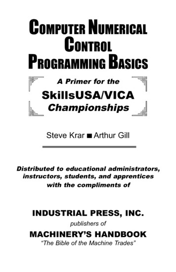
Let’s take a closer look at the geometry of this part.This part has many common turning features: cylindrical faces of varying diameters and lengths,chamfered edges, threads, a groove, and a hole on the center line. 2016 MachiningCloud, Inc.Decision 4: What machining operations are needed? 12
ObservationsMachining RequirementsFirst, take a look at theoverall size and shape ofthe stock and the part.What do you need to do to make the outside dimensions ofthe part the proper size?The stock is a 3” roundbar.Turning operations can be applied to the face and the O.D. ofthe stock to produce a rough outline of the final shape.The largest diameter ofthe part is 2.50”. Thesmallest outer diameter is1.50”.A Finishing operation along the O.D. profile will produce thedesired surface finish.Next, take a look at thedetails on the O.D.A Threading operation can be applied to the 2” diameter.A Grooving operation can be applied to the O.D. groove.There is a flange withexternal threads. Theflange is 2” in diameter x.55” long. The flange hasexternal threads with apitch of 8 threads per inch(TPI).Behind the flange is agroove that is 0.325” wideX 0.200” deep. 2016 MachiningCloud, Inc.Decision 4: What machining operations are needed? 13
Now take a look at anyfeatures inside the part.There is a hole with twodifferent diameters anddepths.The 1” hole has a precise tolerance and a square shoulder atthe bottom. For a hole this size and configuration, it is betterto use a Boring operation to machine the diameter to theprecise size.A Drilling operation can be applied to the 5/8” hole with astandard twist drill.The largest hole has adiameter of 1” with atolerance of plus or minus.001”.The smallest hole has adiameter of 0.625” andhas a standard tolerance. 2016 MachiningCloud, Inc.Decision 4: What machining operations are needed? 14
Decision 5: In what order should operations be performed?There are many ways to program the same workpiece – and all may produce the same finishedpart. Your goal is to seek the most efficient, timely and accurate way to produce each part.Operations are typically organized by which ones remove the most material to the least. Forexample, if the face of a part has a groove, the stock material to the top of the groove isremoved first, and then the groove is cut. Otherwise, the operator would waste time groovingout material that will be removed anyway.Other points to consider when deciding the order of operations: Minimize tool changesMinimize the travel distance between operationsAchieve the shortest cycle time possibleMaintain consistency so machine operators know what to expectThe best way to start is by machining the raw stock to the outer boundaries of the part. In otherwords, you need to “size” the part.In this case, the 3” bar stock needs to be machined to a diameter of 2.5” and a length of 4”,then to a diameter of 2” for a length of 2.375” and then chamfered up at a 45 angle, thendown to 1.5” for a length of 1.5”.1. A facing operation is typically performed first. Facing produces a smooth flat surface atthe front of the part. You can use a G72 Rough Facing Cycle to generate the operationwith only one line (or possibly two lines) of NC code.2. Next you can rough the profile on the O.D. This operation will remove the largestamount of material in the least amount of time. You can use a G71 Rough Turning Cycleto generate the operation with only one line of NC code.3. Now you should finish the same O.D. profile with a G70 Finish Turning Cycle to producea smooth surface finish.You can start filling out your machining process plan using the information from the blueprint. 2016 MachiningCloud, Inc.Decision 5: In what order should operations be performed? 15
The only other features on the O.D. are the groove and the thread. The roughing and finishingoperations removed the material down to the 2” diameter, so now the groove is easier to cut.Cutting the groove first will make it faster and easier to cut the threads.4. Apply a Grooving operation to remove all the material in back of the threaded area.5. Apply a Threading operation to cut the external thread.The last two features to consider are the holes on the inside of the part.6. Drill the 0.625” hole to a depth of 2.25”. Drilling the hole first provides space for an I.D.turning tool.7. Rough the profile on the I.D. Because you are removing material on the I.D., this will bea Boring operation. You can again use a G71 Rough Turning Cycle to simplifyprogramming the NC code.8. Finish bore the 1” diameter to the precise size and surface finish that is specified on theblueprint. Again, use a G70 Finish Turning Cycle. 2016 MachiningCloud, Inc.Decision 5: In what order should operations be performed? 16
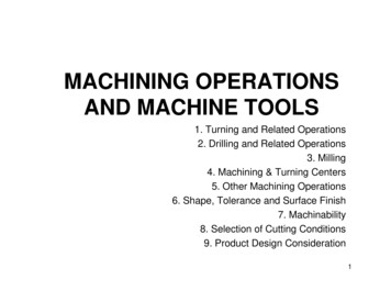
Decision 6: What types of tools are needed?You now know the operations you need to machine this part and the order of those operations.The next step is to decide the type and size of tool to use for each operation.Parameters to be considered: Type of operationPart material/tool materialDepth of cutSmallest concave radiusTool MaterialTurning inserts are typically made of carbide, though ceramic, cermet or diamond inserts canbe applied to more demanding applications.This part is made of aluminum, a relatively soft metal. In this case, general performance carbideinserts are suitable.Turning InsertsTurning inserts are specified by their ANSI insert designation that provides a shorthand methodfor identifying the shape and size of an insert. 2016 MachiningCloud, Inc.Decision 6: What types of tools are needed? 17
CNMG-Shape Clearance Tolerance Type432I.C.SizeThicknessNoseRadiusC and W type turning inserts are often used for rough machining due to their larger point angle,which makes them more rigid.Large point angle: Stronger cutting edgeHigher feed ratesIncreased cutting forcesIncreased vibrationInserts with a smaller point angle, such as D and V, are often used for finish machining.Although they have less strength, the smaller angle can reach more part details.Small point angle: Weaker cutting edgeIncreased access to part detailsDecreased cutting forcesDecreased vibrationTool holders also have ANSI eInsert ReliefAngleHandShank SizeInsert I.C.Length 2016 MachiningCloud, Inc.Decision 6: What types of tools are needed? 18
The most commonly used insert/holder combination for O.D. rough turning and facing is the Ctype 80 diamond insert with a 3-5 negative lead angle tool holder. It is often selected becauseit is the best compromise between strength of insert and end-angle clearance.The face and the O.D. of this part can be roughed with the same tool. A commonly used andcommonly available roughing insert is a CNMG insert (80 Diamond Shape, 0 clearance, .002tolerance, cylindrical opening with double-sided chip breaker). A common size is 1/2" inscribedcircle, 3/16” thick, with a nose radius of 1/32. To hold this insert, you can use a common DCLNholder (clamp-style, C insert, 5 side and end cut, 0 clearance angle).To finish the O.D. profile, you should use an insert with a smaller point angle, such as the Vshape with a 55 point angle. Be sure to use a holder for a V shaped insert.Grooving InsertsGrooving inserts have either a square or round shape on the end. The shape typicallycorresponds to the shape of the groove being cut, although round inserts are the strongestinserts available and are preferred for roughing in demanding situations.When the depth of the groove is greater than the width, a multiple grooving operation ispreferred. Multiple grooving consists of multiple plunge moves into the groove. The width ofthe tool is smaller than the width of the groove to allow for multiple side-by-side cutting passes. 2016 MachiningCloud, Inc.Decision 6: What types of tools are needed? 19
When the width of the groove is greater than the depth, a plunge turning operation is a betterchoice. Plunge turning combines plunging and turning motion, first plunging the tool to ashallow depth of cut, then moving laterally to the opposite end of the groove before plungingagain to the next depth.For the tool holder, the tool overhang should be minimized to improve the stability of the toolduring plunge moves.The width and depth of the groove on this part are about the same size, so the groovingoperation can consist of multiple grooving. The width of the insert should be between 1/8” and3/16” to allow for multiple plunges across the .325” wide groove.Threading InsertsThreads are cut using a 3-point insert called a laydown triangle threading insert.There are three types of threading inserts: Full Profile, Partial Profile, and Multi-Tooth. Full profile inserts cut the full shape of the thread groove, from bottom to top. Theseare useful for high productivity in threading.Partial profile inserts cut the bottom of the thread groove but leave clearance at thetop. These are useful for cutting a range of thread sizes with a small inventory of inserts.Multi-Tooth inserts feature multiple teeth in a series to reduce the number of passesrequired to cut a thread. These are useful for mass production in threading.The major diameter of the thread has already been cut on the O.D., so you do not need to use afull profile threading insert to cut the top of the thread. For versatility, you will use a partialprofile insert with a 60 taper angle that is designed to cut an ACME thread with 8 threads perinch. 2016 MachiningCloud, Inc.Decision 6: What types of tools are needed? 20
Drilling ToolsHSS twist drills are by far the most common tool used for drilling operations. Twist drills areavailable in many sizes and diameters.Choose a twist drill the same size as the 5/8” hole. You will also need a tool holder that isdesigned to hold a drill on a lathe turret.Boring ToolsCylindrical boring bars are used for internal turning. Boring bars consist of a round shaft withone insert pocket. Boring bars are available in steel, solid carbide, and carbide-reinforced steel.You will need a boring bar that will fit into the 5/8” hole that has already been drilled. Whenthe insert is mounted on the boring bar, it also needs to fit inside the 5/8” hole. 2016 MachiningCloud, Inc.Decision 6: What types of tools are needed? 21
Choose a screw-down 3/8” boring bar with a negative 3 lead angle. For both roughing andfinishing, choose a D shape 55 insert. For the roughing operation, a boring bar made of HSS isadequate. For the finishing operation, carbide is more suitable for stability and accuracy.Decision 7: Are the required tools available?Machine shops usually have a range of cutting tools in their tool crib to choose from. When youcreate a process plan, you must ensure that the tools you specified are actually available eitherin the tool crib or from your cutting tool vendor.Cutting tool manufacturers provide catalogs of their cutting tools – both in print and on theirwebsite. Searching for a specific tool in a catalog can be time-consuming and confusing.However, an online application makes it simpler and easier to search for the tools you needfrom different cutting tool manufacturers.Searching for tools in an online databaseMachiningCloud is an independent provider of CNC cutting tool product data. A single source ofaccess to the most current product data from a variety of suppliers, in digital format, availablefrom your desktop. MachiningCloud provides the most up-to-date information, directlyobtained from the manufacturers. The data is formatted very closely to each manufacturer’scatalog system so it is familiar to users. 2016 MachiningCloud, Inc.Decision 7: Are the required tools available? 22
Download the MachiningCloud AppMachiningCloud is a cloud-based software, so it can be downloaded and instantly installed onyour desktop computer or tablet. All your information is always available on any device uponlogging into your account.1.2.3.4.From your computer or mobile device, open your Internet browser.Enter the following URL address: https://www.machiningcloud.comOn the home page, click DOWNLOAD APP.Choose your desired platform from the dropdown list. Choices include Android, iPad,Windows Desktop.5. Then click Download MachiningCloud.6. On your desktop, look for your software to be downloading. If you are prompted toOpen/Run or Save the file, click the Save button.7. On your mobile device, tap Install.Install the MachiningCloud App1. On your desktop, click the downloaded program to start the installation.2. Choose your preferred language and click OK.3. Scroll through and read the End User License Agreement. Accept the terms of thelicense agreement and click Next.4. Choose the Standard installation and click Next.5. Click Install. Installation of the app only takes a few seconds.6. Click Run App.7. You will need to sign up for an account so you can store your tooling data in the cloud.Click Sign up for an account.8. Type your information in the mandatory fields. You must enter your: First Name Last Name Your Email Confirm Email9. When you are finished entering information, click Register. You will be prompted for apassword.10. Enter a unique Password and then enter the same password to Confirm Password.Search for cutting tools in the MachiningCloud online databasesThe MachiningCloud has partnered with several cutting tool manufacturers. This lesson willshow you how to select a tool manufacturer and search for tools in their online database.You are not restricted to one manufacturer in the MachiningCloud. You will see how to selectcutting tools from different tool manufacturers and add them to your personal tool list. 2016 MachiningCloud, Inc.Decision 7: Are the required tools available? 23
1. Tap or double-click the MachiningCloud icon on your desktop or device to launch theApp.2. On the Home page, tap or click Select Tool Manufacturer.Several tool manufacturers are available. You will first take a look at the Kennametaldatabase of tools.3. Choose Kennametal.You are returned to the Home page automatically and the logo for Kennametal isdisplayed at the top of the screen.Search for an O.D. roughing tool1. On the Home page, click Search for a tool in the electronic catalog.2. Tap or click O.D. and I.D. Turning.3.4.5.6.7.Tap or click General Performance Inserts.Tap or click Negative Style Inserts.Tap or click CNMG-F.In the list of inserts, select CNMG432F.Click Add To and then choose My Tools.The insert is added to your personal tool list under My Workshop. Now you cansearch for a tool holder.8. With the tool selected, click Open.9. Click Add Tool Item.10. Notice the Filters window at the right side of the screen. You can use filters tonarrow your search. You are looking for a DCLN holder, so type DCLN in the searchbox and then click the Search icon.11. Click DCLN-KC -5 .12. Select the holder with the 1” x 1” x 6” long shank and click Add to Tool Assembly.Search for an O.D. grooving tool1. Click the Home button at the left top corner of the screen. 2016 MachiningCloud, Inc.Decision 7: Are the required tools available? 24
2. Click Search for a tool in the electronic catalog.3. Click Turning.4. Click Grooving and Cut-Off.5. Click Grooving.6. In the Filters screen, set Workpiece Material to N Non-Ferrous Materials.7. Open the Insert Geometry filter and set Insert Seat Size to 3 and click Apply Filter.8. Open the Front-End filter and choose a Cutting Width of 0.125.9. Set Insert Shape to Groove/Cutoff and click Apply Filter.10. Open the Corner Configuration filter and set Corner Radius to .016.11. In the main screen, click the GMN insert type.12. Select an insert with a grade suitable for aluminum.13. At the bottom of the screen, click Add To and add the insert to My Tools.14. In the tools screen, click Open and then click Add Tool Item.15. Use the filters to search for a tool holder for grooving applications with a 0.75” shank.16. Choose a holder and add it to your tool assembly.Your list of tools is saved in the cloud and you can return to it at any time. 2016 MachiningCloud, Inc.Decision 7: Are the required tools available? 25
Decision 8: What feeds and speeds should I use?Surface Feet Per Minute (SFM) is a combination of the cut diameter and RPM. SFM is aconstant, with RPM as a variable based upon cut diameter.Materials will run better at specific SFMs. The recommended SFM for cutting aluminum on alathe falls in a range from 150 to 400.When the SFM constant is known for a specific material, the formula below can be used todetermine spindle speed for turning various materials.RPM SFM x (12/Pi) / Cut DiameterRevolutions Per Minute (RPM) relates directly to the speed, or velocity, of the spindle. Itannotates the number of turns completed in one minute around a fixed axis. RPM maintainsthe same revolutions per minute throughout the entire operation.RPM mode (G97) is useful for: Center cutting operations (drilling)When the diameter at the beginning and end of a cut only differs slightlyDuring threading to allow the perfect synchroniza
standard turning operations . This class is intended for lathe operators and students in a turning operator training program who understand how to set up and run a turning machine. Students should be able to identify common types of turning tools, tool hol