Transcription
BASIC AC ELECTRICALGENERATORSFREE DOWNLOAD
(This page left blank intentionally)
BASIC AC ELECTRICAL GENERATORSTABLE OF CONTENTSIntroduction . 1Generator Types . 4Rotating Armature Generator . 4Rotating Field Generator. 5Polyphase Generators . 7Air Cooled Generators . 10Temperature Rise . 10Reliability. 11Construction. 11Generator Design and Construction . 11Generator Stator and Windings . 11Stator Design Hydrogen/Water Cooled Stators . 17GENERATOR ROTORS. 19Salient Pole Rotors . 19Cylindrical Generator Rotor . 20Rotor Design Air Cooled Generators. 25Rotor Design Hydrogen/Water Cooled Generators . 27Rotor Mechanical Design . 29Hydrogen Cooled Generator Stator . 31Generator Isolated Phase Bus. 33Standard Generator Seal Oil System . 35Standard Generator Stator Cooling Water System . 43
BASIC AC ELECTRICAL GENERATORSExcitation Systems . 49Progress Check . 52Answers . 56Final Examination . 58
BASIC AC ELECTRICAL GENERATORS(This page left blank intentionally)
BASIC AC ELECTRICAL GENERATORSPREFACEThis training module has been developed to provide you with information pertaining todevices known as Basic AC Electric Generators. The information in this training moduleis designed to increase your knowledge and improve your abilities as they relate to themodule. Within the training module you will find information pertaining to variousdesigns of electrical generators, code requirements, associated accessories, as well asrelated mathematical principles and their solutions. Additionally, the training moduleincludes associated review questions and answers so that you can gauge yourcomprehension of the subject material. Subject matter within the module helpsprepares the student to take related state, city, and American Society of PowerEngineers Licensing exams.Information contained in this lesson has been obtained by O&M Consulting Services Incfrom sources believed to be reliable. Neither however O&M Consulting Services Inc norits authors guarantee the accuracy or completeness of any information published herein,and neither O&M Consulting Services Inc and its authors shall be responsible for errors,omissions, or damages arising out of use of this information. This work is published withthe understanding that O&M Consulting Services Inc and its authors are supplyinginformation but are not attempting to render engineering or other professional services. Ifsuch services are required, the assistance of an appropriate professional should besought. O&M Consulting Services Inc has supplied American Society of Power EngineersInc with this Training Module at no charge for free distribution. This document may notbe resold; it is for informational purposes only.
BASIC AC ELECTRICAL GENERATORS(This page left blank intentionally)
BASIC AC ELECTRICAL GENERATORSIntroductionFaraday’s Law; when you see that rotation of the coil continually changes the magneticflux through the coil and therefore generates a voltage. Generators, motors,transformers, and solenoids each use the principle of electromagnetism. This is theability to create electrical current in a conductor by moving a magnetic field past theconductor. The reverse is also true: a magnetic field is produced in a conductor bypassing electrical current through the conductor. In general, the requirements forelectromagnetism are a magnetic field, a conductor, and relative movement betweenthem.A permanent magnet has a magnetic field around it. The field is lines of magnetism(flux) that bend around the metal magnet. The strongest part of the magnetic field is theregion where the lines are closest together. On a permanent magnet, there are twosuch regions, one at each end of the magnet. These are called the north and so uthpoles of the magnet. (The earth is a magnet, with the strongest part of the magneticfield at the North and South Poles Magnetic of the earth.)A simple generator has two basic parts – field and winding. The field is the magneticfield and the winding is the conductor formed into a coil.FieldSWindingNThe field is connected to a shaft that may be turned. These are two elementsnecessary for electromagnetism. When the turning field is placed near the winding, allof the elements are present for electromagnetism. (In fact, the field could be fixed andthe windings turned to produce the same effect in a generator. However, this-1-
BASIC AC ELECTRICAL GENERATORSarrangement is normally used for small generators, where the current produced in thewinding is small.)As the field turns past the fixed winding, the amount of current produced in the windingdepends upon the strength of the magnetic field moving past the winding. As the NorthPole of the field moves past the winding, a large current flows through the winding.FieldSNWindingAs the field continues to turn and the North Pole starts to move away from the winding,the current decreases as the strength of the field “cutting” the winding decreases.When neither pole is nearest the winding, the current through the winding is zero.SWindingFieldNAs the field continues to turn, the South Pole moves toward the winding as the NorthPole moves away. Current starts to flow in the winding, but in the opposite direction,because of the opposite pole moving closer to the winding. When the South Pole isopposite the winding, the current is again strong, but in the opposite direction.FieldNS-2-Winding
BASIC AC ELECTRICAL GENERATORSAs the South Pole moves away, the current in the winding decreases, returning to zeroagain when neither pole is close to the winding.While this simple generator produces AC (alternating current), the current produced isnot very large since the strength of the magnetic field is not very large. The principle ofelectromagnetism may be used to produce a magnetic field of much greater strength. Ifa conductor is wound around a piece of metal, such as iron or steel, and current ispassed through that conductor, a magnetic field is produced around this assembly. It iscalled an electromagnet.NNSSThe strength of the magnetic field produced is determined by the amount of currentpassing through the conductor. When a stronger magnetic field passes a winding, morecurrent is produced in the winding. In a generator, the amount of current produced inthe winding can thus be controlled by controlling the amount of current passi ng throughthe co nductor ca usi ng the magnetic field.The three-phase generator is basically three separate generators in one casing. It hasthree completely separate windings in which current is produced, but a single rotatingmagnetic field. Within the generator, there is no electrical connection between thewindings. The rotating magnetic field is the rotor and the windings in which current isproduced are in the fixed stator.-3-
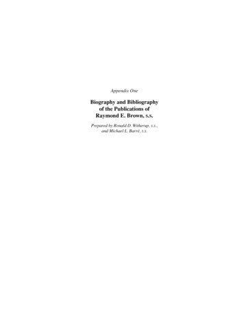
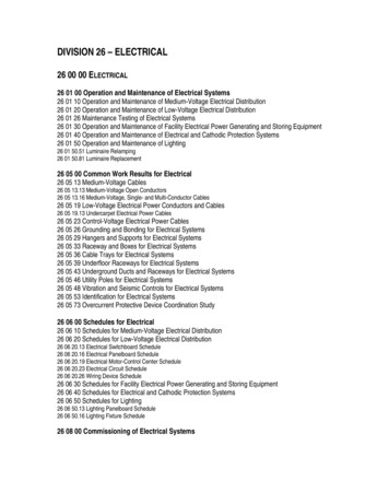
BASIC AC ELECTRICAL GENERATORSGenerator TypesVarious types of alternating current generators are utilized today; however, they allperform the same basic function. The types discussed in the following paragraphs aretypical of the more predominant ones in use.Rotating Armature GeneratorIn the rotating armature AC generator as illustrated in Figure 1, the stator provides astationary electromagnetic field. The rotor, acting as the armature, rotates in the field,cutting the lines of force and producing the desired output voltage. The output voltageis taken from the rotor by the slip rings and brushes. One slip ring is attached to eachend of the rotating loop. The brushes make sliding electrical contact with the slip rings.The generator's AC output voltage can be transferred from the slip rings through thebrushes to an external circuit.Figure 1. Rotating Armature Generator-4-
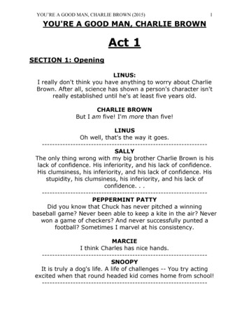
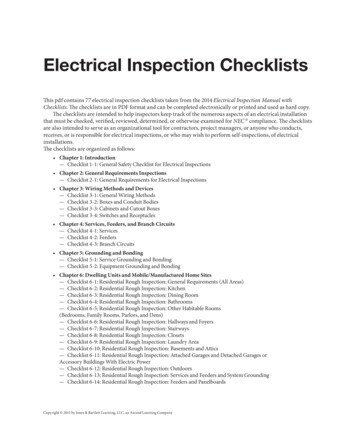
BASIC AC ELECTRICAL GENERATORSRotating armature AC generators are typically used in applications involving smallamounts of power. With larger amounts of power, a great deal more current flow occursthrough the slip rings and brushes. It is difficult and expensive to build slip rings andbrushes to carry large amounts of current. Therefore, most large AC generators arerotating field generators.Rotating Field GeneratorThe rotating field AC generator as illustrated in Figure 2 is by far the most widely usedgenerator. In this type of generator, direct current from a separate source is passedthrough windings on the rotor by means of slip rings and brushes. This maintains arotating electromagnetic field of fixed polarity (similar to a rotating bar magnet). Therotating magnetic field of the rotor extends outward and cuts through the armaturewindings embedded in the surrounding stator. As the rotor turns, alternating voltagesare induced in the windings because magnetic fields of first one polarity and then theother cut through them. Beca use the output power is take n from stationary windings,the output may be connected through fixed terminals. The advantage in this type ofconstruction is that larger amounts of currents can be handled because there are nosliding co ntacts and the whole output circuit is co ntinuously insulated.-5-
BASIC AC ELECTRICAL GENERATORSFigure 2. Rotating Field GeneratorSlip rings and brushes are adequate for the DC field supply because the current level inthe field is much smaller than in the armature circuit.-6-
BASIC AC ELECTRICAL GENERATORSPolyphase GeneratorsMost electric power is generated and distributed as three-phase rather than si nglephase power for the following reasons: The cost of transmission is less than for the same voltage and power in a singlephase system. A three-phase generator has a 180% greater capacity than a single phasegenerator of the same physical size. Single-phase voltage and power is easily available from a three-phase system bymerely tapping any two of the power leads.A three-phase AC generator is designed to produce three-phase AC power by buildingmore coils in the stator around the rotor. The three coils are equally spaced 120 apartaround the inside of the stator. The armature coils are wired so that the generator hasthree separate output voltages that differ in phase by 1200.Figure 3 illustrates a simplified three-phase, two pole AC generator. Each of the threecoils generates an AC voltage sine wave as illustrated in Figure 4a and 4b. The voltagewave (phase) B begins one third of the way into the A wave cycle, and the C wavebegins two thirds of the way into the A wave cycle. This relationship is caused by theposition of the coils in the stator. When the voltage in phase A has reached its peakpositive value and is returning to zero, the voltage in phase B has reached its peaknegative value and is beginning to return to zero. The voltage in phase C has passedzero and a negative voltage is being induced. During a three-phase voltage cycle, theoverall voltage induced is never zero.-7-
BASIC AC ELECTRICAL GENERATORSFigure 3. Simplified Three-Phase AC GeneratorFigure 4. Voltage Output of a Three-Phase Generator-8-
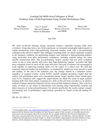
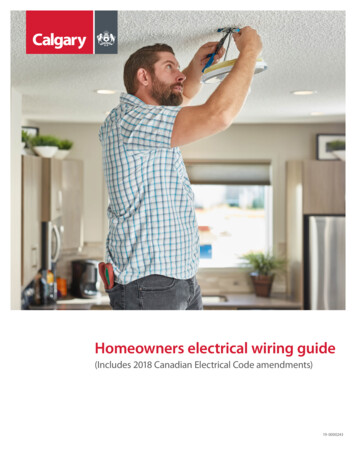
BASIC AC ELECTRICAL GENERATORSGenerators Used In Power GenerationGenerators used in power generation applications can be placed in three major designclassifications based on the cooling medium used: air, hydrogen or liquid cooled. Howwell the armature winding of a generator is cooled has a significant influence on theoverall size of a synchronous generator. The cooling of the armature winding isdependent on a number of factors: cooling medium (air, hydrogen, water); insulationthickness; and overall electrical losses (12 R load loss). As Figure 5 illustrates,relative heat removal capability improves from air to hydrogen, with increased hydrogenpressure, and even more significant with the use of water 61.04.04.161000.00.01250.0HYDROGEN 30 PSIG(2.07 BAR)HYDROGEN 45 PSIG(3.10 BAR)WATERFigure 5. Generator Heat Removal Capabilities of Various FluidsConventional hydrogen cooling can be utilized on generators rated below 300 MVA,while direct water cooling of armature windings is applied to units above 250 MVA. Thisdivision results from design optimization. While it is possible to apply water cooling onmachines rated below 250 MVA, the cost/performance benefit suffers. Water coolingadds manufacturing complexity, as well as, requires the need for auxiliary water cooling-9-
BASIC AC ELECTRICAL GENERATORSand de-ionizing skid, plus associated piping, control and protection features. At higherratings, the cost of this complexity is offset by the advantage of producing a generator ofsignificantly smaller size than a comparable conventionally cooled generator. Anoverview of each of the basic design classifications is provided in the following section.Air Cooled GeneratorsAir cooled generators are produced in two basic configurations: open ventilated (OV)and totally enclosed water to air cooled (TEWAC). In the OV design, outside air isdrawn directly from outside the unit through filters, passes through the generator and isdischarged outside the generator. In the TEWAC design, air is circulated within thegenerator, passing through frame mounted air to water heat exchangers.The recent emphasis in the marketplace on steam and gas turbine generators in the 20to 100 MVA size has forced manufacturers to restructure their air cooled machines. Aconsequence of the historical development of the turbine generator market was that twolines of generator applications evolved, one for steam turbine applications and the otherfor gas turbine applications, with little standardization between the designs. As a resultof design restructuring, several design and operational issues, which were judged to becritical to the reliability and standardization of generators were identified. Among theseissues were performance parameters, availability of features, cycle time and costeffectiveness.The basic design of a generator is influenced primarily by material and electromagneticproperties, as well as winding temperature rise, industry standards, generator ratings,reliability, etc. A short discussion of the critical factors follows:Temperature RiseIn the early 1970’s, gas turbine manufacturers introduced insulation systems capable ofoperating at Class F temperatures (155 C, 311 F) for the life of the generator. This- 10 -
BASIC AC ELECTRICAL GENERATORSenabled a significant up rating of generator designs (about 10%) with a minimalincrease in cost. To capitalize on this technical capability, manufacturers designedgenerators with class F insulation and Class F temperature rises. Many suchgenerators are in service and operating successfully.ReliabilityTo improve generator reliability, manufacturers pay particular attention to knownproblem areas based on in service generator experience. The new designs strive for ahigh level of reliability and availability based on the problems that have caused downtime on older designs. In addition, the reliability of the product is improved throughdesign simplification and standardization, discussed below.ConstructionGenerator Design and ConstructionAs we go thought the generator design and construction the differences betweenhydrogen cooled and air cooled will be pointed out. There are two main components inthe generator, the rotor and the stator. The generator must also have a source of DCcurrent to magnetize the rotor, called the exciter. The generator may have severalcomponents and subsystems, depending on its particular features. The following is adiscussion on the main components of a generator.Generator Stator and WindingsThe generator stator, also called the armature, supports the iron core and windings, therotor, and the compartment coolers reference Figure 6 and 7. The stator consists of asteel plate casing called the "wrapper" that covers a frame that in turn holds the ironcore. An iron core is used in order to produce a stronger magnetic field for thegeneration of voltage. There are tubes within the wrapper to help distribute cooling gas.Older units use air at atmospheric pressure for cooling. Newer generators use- 11 -
BASIC AC ELECTRICAL GENERATORShydrogen under pressure (from 15 to 75 psig) for cooling. Hydrogen is more effectivethan air in dissipating heat, and the higher the hydrogen pressure, the more effectivethe hydrogen is in removing heat.Figure 6. Generator StatorFigure 6 illustrates a typical stator. The core is made up of thousands of laminatedsteel sheet metal punchings, each of which is insulated from the others. Note that thecore is referred to as "iron" even though it is made up of these steel punchings. Theinsulation is necessary to avoid creating large currents in the core that would cause it toheat up to an unacceptably high temperature. The punchings are "stacked" with spacesbetween groups of punchings to allow for cooling ventilation.- 12 -
BASIC AC ELECTRICAL GENERATORSFigure 7. Typical Stator CoreFigure 8. Typical Stator Punching- 13 -
BASIC AC ELECTRICAL GENERATORSThe windings or conductors for the stator take the form of long copper bars that arewrapped with insulation. The bars fit into the longitudinal slots on the inside diameter ofthe core and are held in place by wedges that slide into the top of the slot. Figure 9illustrates the assembly of the bars in a slot. Note that there are generally two bars, oneon the top and the other beneath, in each slot.Figure 9. Generator Stator Construction DetailSome generators have liquid cooled stator windings; the liquid may be oil, or moreoften, water. In these units the copper bars have many passages along their length forliquid to flow.The stator windings are tied together at the ends of the stator and are brought outthrough the casing through a bolted on assembly called the lower frame extension (oras it is sometimes called, the bath tub) at the bottom to terminals. There are generallysix terminals, one for each end of each of the three phases in the windings.- 14 -
BASIC AC ELECTRICAL GENERATORSThe stator frame is divided onto an inner and an outer section, both of which mount on asingle base fabrication. The inner frame is a very simple structure designed to supportthe stator core and winding while providing some guidance to the air flow in themachine. The stator core, made from grain oriented silicon steel for low loss and highpermeability, is mounted rigidly in the inner frame. Isolation of the core vibration fromthe remainder of the structure is accomplished through the use of flexible pads betweenthe feet on the inner frame and the base structure.The outer frame is a simple fabricated enclosure, which supports both the air inlets andsilencers (if the unit is open ventilated or the roof and cooler enclosure (if the unit istotally enclosed, water-to-air-cooled). The outer frame further acts as an air guide tocomplete the ventilation paths it also acts as a soundproof enclosure to keep noiselevels low. Since the rotor is pedestal mounted, the end shields are very simplestructures.The entire generator is mounted on a single fabricated base, which supports thepedestals, the inner and outer frames, and the brush rigging or the exciter. The basecontains piping for oil supplies, conduit for wiring and a number of componentsassociated with the main leads, such as lightning arresters and surge capacitors. Thestructural vibration of the base is confirmed by tests to verify the vibration frequency iswell away from any frequency of concern.The stator winding is a conventional lap wound design. The insulating materials havebeen in use since the early 1970’s, thus maintaining the proven reliability record. Thematerials are all designed and tested to provide reliable performance at Class Ftemperatures for the life of the machine. The bars are secured in the slots with fillersand top ripple springs to restrain the bars radically, and with side ripple springs toincrease friction between the bar and the slot wall. The side ripple springs are alsoconducting to ensure proper grounding of the bar surface. The end winding support- 15 -
BASIC AC ELECTRICAL GENERATORSsystem is the proven approach used on conventionally cooled stators of all sizes built byGE. This system utilizes resin impregnated glass roving ties.Figure 10. Spring MountingHydrogen-cooled generator construction except for the frame is very similar to that of aircooled generators. Most designs use direct radial flow cooling similar to that shown inFigure 11. The stator frame, on the other hand, because of the need to contain 30 psigto 75 psig hydrogen, uses thick plate cylindrical construction. End shields are morerugged and contain a hydrogen seal system to minimize leakage. Conventionalhydrogen cooling, while available for generators rated below 100 MVA, is most oftenapplied to gas and steam turbine driven units above 100 MVA.- 16 -
BASIC AC ELECTRICAL GENERATORSFigure 11. Hydrogen Cooled Generator Cooling FlowStator Design Hydrogen/Water Cooled StatorsEven more compact generator designs are achievable through the use of direct watercooling of the generator armature winding. These designs employ hollow copperstrands through which deionized water flows. The cooling water is supplied by a closedloop auxiliary-base-mounted skid. The cool water enters the winding through adistribution header on the connection end of the generator Reference Figure 12. Thewarm water is discharged in a similar manner on the turbine end of the generator.The armature voltage and current of a hydrogen/water-cooled generator is significantlyhigher than those of air or hydrogen cooled units. As a result, the insulation voltagestress and forces on the armature windings can be several orders of magnitude largerthan those experienced on lower rated units. These present unique designrequirements that must be addressed if high reliability and long life of the equipment isto be maintained.- 17 -
BASIC AC ELECTRICAL GENERATORSFigure 12. Stator End Winding ConfigurationThe stator insulation material used in modern GE water-cooled generators consists ofan epoxy mica based system called Micapal TM. MicapalTM I was introduced in 1954,partially as a solution to tape migration and girth cracking problems associated withasphalt insulation based systems.In the mid 1970's, an improved epoxy mica system was introduced (Micapal TMII). Thisall mica paper insulation has improved mechanical toughness and voltage endurance.While these properties were developed to meet the requirements of very large ratings,the application of MicapalTMII on small and mid size units permits further optimizationopportunities. Micapal TMII has exce llent thermal cycling capability, and is particularlysuited for the daily start/stop duty required of many gas turbine generators today.- 18 -
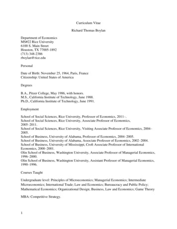
BASIC AC ELECTRICAL GENERATORSGENERATOR ROTORSSalient Pole RotorsOne of the two types of rotors typically installed within large generators is the salientpole rotor (Figure 13 A). Salient pole rotors have large diameters and large massmaking them ideal for slower spinning rotors, such as on hydroelectric generators. Thegreater inertia (inertia is a function of the weight, speed of rotation, and diameter)associated with this type of rotor, helps maintain a constant frequency in the powersystem.Each field pole of a salient pole rotor has a pole running lengthwise along the cylindershaped rotor (see Figure 13 A). The pole functions in a similar manner to the core of atransformer. Each pole is wrapped with windings its entire length to form the pole. Thewindings are made of an insulated copper conductor. A field winding is formed byconnecting the windings of each field pole in series with each adjacent field pole. It istermed the field winding since it provides the magnetic field for the generator. Note thatin large, modern generators, the rotor will always contain the field winding.Figure 13 A. Salient Pole- 19 -
BASIC AC ELECTRICAL GENERATORSCylindrical Generator RotorCylindrical rotors (Figure 13) are used on higher speed generators, such as steamturbine driven generators, due to their faster rotational speed. Higher speed generatorswould literally tear apart a large salient pole rotor due to the centrifugal force associatedwith the large diameter and weight. Note that a great amount of inertia is still presentwith cylindrical rotors due to their high speed of rotation.A cylindrical rotor is a solid steel shaft with slots that run lengthwise along the outside ofits cylindrical shape. Laminated copper bars are inserted within the slots and theseconductors are kept stationary with metal wedges. These copper bars form the fieldwinding of the rotor.The rotor acts as a large electromagnet. When it turns inside the stator, it induces avoltage and current in the stator windings. The rotor takes the form of a long cylinderwith slots machined along its length reference Figure 13 B. Copper windings fit intothese slots and are held in place by wedges that slide into the top of the slots. The slotsare insulated from the windings, and each turn of the winding is insulated from the nextturn. The windings are held at the ends of the rotor by retaining rings. The wedges andwindings often have holes or slots in them to allow cooling gas to flow.Figure 13 B. Generator Rotor- 20 -
BASIC AC ELECTRICAL GENERATORSThe rotor is usually connected directly to a prime mover such as a steam turbine in asteam unit or a hydraulic turbine in a hydroelectric unit. Thus, the speed at which therotor turns and the power output of the generator is determined by the speed at whichthe turbine spins and the energy input to the turbine. Two pole (3600 rpm) generatorsare typically used in coal-fired steam units, due to the high pressures and temperaturesassociated with the steam. That is there is one winding in the field and it acts as one,large electromagnet with two poles as illustrated in Figure 14 and 15. Nuclear powerplants typically use four-pole rotors. Four-pole rotors are used because a nuclear unit’ssteam temperature and pressure are lower and the lower the energy content of thesteam, the larger the turbine has to be. It would not be safe to rotate large steamturbines at 3600 rpm.Gas turbines typically use two pole rotors although the turbine itse lf may spin at a higherspeed and use some method of gear reduction to connect to the machine rotor. Mostmodern day gas turbines or combustion turbines turn at 3600 RPMs.Hydroelectric generators rotate at much slower speeds due to the energy in the waterused to turn the hydraulic turbine. Most hydroelectric units rotate below 300 rpmresulting in a high number of poles. For example, a hydroelectric generator with arotating speed of 100 RPM will have 72 poles. The number of poles and the rotatingspeed used for a hydroelectric unit varies greatly depending on the characteristics(difference in incoming versus outgoing water elevation, etc.) of the particular waterresource where a unit is located.- 21 -
BASIC AC ELECTRICAL GENERATORSFigure 14. Generator RotorFigure 15. Two Poles Imbedded in the RotorThere are fans mounted on the ends of the rotor to circulate cooling gas inside thegenerator stator. The fans may be axial or centrifugal as illustrated in Figure 16.- 22 -
BASIC AC ELECTRICAL GENERATORSFigure 16. Fan Mounted On the End of RotorAn operator will have to adjust the frequency of the gene
transformers, and solenoids each use the principle of electromagnetism. This is the ability to create electrical current in a conductor by moving a magnetic field past the conductor. The reverse is also true: a magnetic field is produced in a conductor by passing electrical curren