Transcription
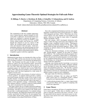
OPTICAL MICROSCOPYDavidson and AbramowitzOPTICAL MICROSCOPYMichael W. Davidson1 and Mortimer Abramowitz21National High Magnetic Field Laboratory, The Florida State University, 1800 E. Paul Dirac Dr., Tallahassee, Florida 32306,davidson@magnet.fsu.edu, http://microscopy.fsu.edu2Olympus America, Inc., 2 Corporate Center Dr., Melville, New York 11747, abramm@olympus.com, http://www.olympus.comKeywords: microscopy, phase contrast, differential interference contrast, DIC, polarized light, Hoffmanmodulation contrast, photomicrography, fluorescence microscopy, numerical aperture, CCD electronic cameras,CMOS active pixel sensors, darkfield microscopy, Rheinberg illumination.binocular microscopes with image-erecting prisms, andthe first stereomicroscope (14).Early in the twentieth century, microscopemanufacturers began parfocalizing objectives, allowing theimage to remain in focus when the microscopist exchangedobjectives on the rotating nosepiece. In 1824, Zeissintroduced a LeChatelier-style metallograph with infinitycorrected optics, but this method of correction would notsee widespread application for another 60 years.Shortly before World War II, Zeiss created severalprototype phase contrast microscopes based on opticalprinciples advanced by Frits Zernike. Several years laterthe same microscopes were modified to produce the firsttime-lapse cinematography of cell division photographedwith phase contrast optics (14). This contrast-enhancingtechnique did not become universally recognized until the1950s and is still a method of choice for many cellbiologists ts in Wollaston prism design for anotherpowerful contrast-generating microscopy theory in 1955(15). This technique is commonly referred to asNomarski interference or differential interferencecontrast (DIC) microscopy and, along with phase contrast,has allowed scientists to explore many new arenas inbiology using living cells or unstained tissues. RobertHoffman (16) introduced another method of increasingcontrast in living material by taking advantage of phasegradients near cell membranes. This technique is nowtermed Hoffman Modulation Contrast, and is available asoptional equipment on most modern microscopes.The majority of microscopes manufactured around theworld had fixed mechanical tube lengths (ranging from160 to 210 millimeters) until the late 1980s, whenmanufacturers largely migrated to infinity-correctedoptics. Ray paths through both finite tube length andinfinity-corrected microscopes are illustrated in Figure1. The upper portion of the figure contains the essentialoptical elements and ray traces defining the optical trainIntroductionThe past decade has witnessed an enormous growth inthe application of optical microscopy for micron and submicron level investigations in a wide variety of disciplines(reviewed in references 1-5). Rapid development of newfluorescent labels has accelerated the expansion offluorescence microscopy in laboratory applications andresearch (6-8). Advances in digital imaging and analysishave also enabled microscopists to acquire quantitativemeasurements quickly and efficiently on specimensranging from photosensitive caged compounds andsynthetic ceramic superconductors to real-timefluorescence microscopy of living cells in their naturalenvironment (2, 9). Optical microscopy, with help ofdigital video, can also be used to image very thin opticalsections, and confocal optical systems are now inoperation at most major research institutions (10-12).Early microscopists were hampered by opticalaberration, blurred images, and poor lens design, whichfloundered until the nineteenth century. Aberrations werepartially corrected by the mid-nineteenth century with theintroduction of Lister and Amici achromatic objectivesthat reduced chromatic aberration and raised numericalapertures to around 0.65 for dry objectives and up to 1.25for homogeneous immersion objectives (13). In 1886,Ernst Abbe’s work with Carl Zeiss led to the productionof apochromatic objectives based for the first time onsound optical principles and lens design (14). Theseadvanced objectives provided images with reducedspherical aberration and free of color distortions(chromatic aberration) at high numerical apertures.Several years later, in 1893, Professor August Köhlerreported a method of illumination, which he developedto optimize photomicrography, allowing microscopists totake full advantage of the resolving power of Abbe’sobjectives. The last decade of the nineteenth century sawinnovations in optical microscopy, includingmetallographic microscopes, anastigmatic photolenses,1
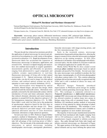
OPTICAL MICROSCOPYof a conventional finite tube length microscope (17). Anobject (O) of height h is being imaged on the retina ofthe eye at O”. The objective lens (Lob) projects a realand inverted image of O magnified to the size O’ into theintermediate image plane of the microscope. This occursat the eyepiece diaphragm, at the fixed distance fb z’behind the objective. In this diagram, fb represents theback focal length of the objective and z’ is the optical tubelength of the microscope. The aerial intermediate imageat O’ is further magnified by the microscope eyepiece(Ley) and produces an erect image of the object at O” onthe retina, which appears inverted to the microscopist.The magnification factor of the object is calculated byconsidering the distance (a) between the object (O) andthe objective (Lob) , and the front focal length of theobjective lens (f). The object is placed a short distance(z) outside of the objective’s front focal length (f), suchthat z f a. The intermediate image of the object, O’, islocated at distance b, which equals the back focal lengthof the objective (fb) plus (z’), the optical tube length ofthe microscope. Magnification of the object at theintermediate image plane equals h’. The image height atthis position is derived by multiplying the microscopetube length (b) by the object height (h), and dividing thisby the distance of the object from the objective: h’ (h xb)/a. From this argument, we can conclude that the lateralor transverse magnification of the objective is equal to afactor of b/a (also equal to f/z and z’/fb), the back focallength of the objective divided by the distance of the objectfrom the objective. The image at the intermediate plane(h’) is further magnified by a factor of 25 centimeters(called the near distance to the eye) divided by the focallength of the eyepiece. Thus, the total magnification ofthe microscope is equal to the magnification by theobjective times that of the eyepiece. The visual image(virtual) appears to the observer as if it were 10 inchesaway from the eye.Most objectives are corrected to work within a narrowrange of image distances, and many are designed to workonly in specifically corrected optical systems withmatching eyepieces. The magnification inscribed on theobjective barrel is defined for the tube length of themicroscope for which the objective was designed.The lower portion of Figure 1 illustrates the opticaltrain using ray traces of an infinity-corrected microscopesystem. The components of this system are labeled in asimilar manner to the finite-tube length system for easycomparison. Here, the magnification of the objective isthe ratio h’/h, which is determined by the tube lens (Ltb).Note the infinity space that is defined by parallel lightbeams in every azimuth between the objective and the tubelens. This is the space used by microscope manufacturersto add accessories such as vertical illuminators, DICDavidson and AbramowitzFigure 1. Optical trains of finite-tube and infinity-correctedmicroscope systems. (Upper) Ray traces of the optical trainrepresenting a theoretical finite-tube length microscope. The object(O) is a distance (a) from the objective (Lob) and projects anintermediate image (O’) at the finite tube length (b), which is furthermagnified by the eyepiece (Ley) and then projected onto the retinaat O’’. (Lower) Ray traces of the optical train representing atheoretical infinity-corrected microscope system.prisms, polarizers, retardation plates, etc., with muchsimpler designs and with little distortion of the image(18). The magnification of the objective in the infinitycorrected system equals the focal length of the tube lensdivided by the focal length of the objective.Fundamentals of Image FormationIn the optical microscope, when light from themicroscope lamp passes through the condenser and thenthrough the specimen (assuming the specimen is a lightabsorbing specimen), some of the light passes both aroundand through the specimen undisturbed in its path. Suchlight is called direct light or undeviated light. Thebackground light (often called the surround) passingaround the specimen is also undeviated light.Some of the light passing through the specimen isdeviated when it encounters parts of the specimen. Suchdeviated light (as you will subsequently learn, calleddiffracted light) is rendered one-half wavelength or 1802
OPTICAL MICROSCOPYdegrees out of step (more commonly, out of phase) withthe direct light that has passed through undeviated. Theone-half wavelength out of phase, caused by the specimenitself, enables this light to cause destructive interferencewith the direct light when both arrive at the intermediateimage plane located at the fixed diaphragm of theeyepiece. The eye lens of the eyepiece further magnifiesthis image which finally is projected onto the retina, thefilm plane of a camera, or the surface of a light-sensitivecomputer chip.What has happened is that the direct or undeviated lightis projected by the objective and spread evenly across theentire image plane at the diaphragm of the eyepiece. Thelight diffracted by the specimen is brought to focus atvarious localized places on the same image plane, wherethe diffracted light causes destructive interference andreduces intensity resulting in more or less dark areas.These patterns of light and dark are what we recognize asan image of the specimen. Because our eyes are sensitiveto variations in brightness, the image becomes a more orless faithful reconstitution of the original specimen.To help understand the basic principles, it is suggestedthat readers try the following exercise and use as aspecimen an object of known structure, such as a stagemicrometer or similar grating of closely spaced darklines. To proceed, place the finely ruled grating on themicroscope stage and bring it into focus using first a 10xand then the 40x objective (18). Remove the eyepieceand, in its place, insert a phase telescope so the rear focalplane of the objective can be observed. If the condenseraperture diaphragm is closed most of the way, a brightwhite central spot of light will appear at the back of theobjective, which is the image of the aperture diaphragm.To the right and left of the central spot, a series of spectra(also images of the aperture diaphragm) will be present,each colored blue on the part closest to the central spotand colored red on the part of the spectrum farthest fromthe central bright spot (as illustrated in Figure 2). Theintensity of these colored spectra decreases accordingto how far the spectrum is from the central spot (17,18).Those spectra nearer the periphery of the objectiveare dimmer than those closer to the central spot. Thediffraction spectra illustrated in Figure 2 using threedifferent magnifications. In Figure 2(b), the diffractionpattern visible at the rear focal plane of the 10X objectivecontains two diffraction spectra. If the grating is removedfrom the stage, as illustrated in Figure 2(a), these spectradisappear and only the central image of the aperturediaphragm remains. If the grating is reinserted, the spectrareappear once again. Note that the spaces between thecolored spectra appear dark. Only a single pair of spectracan be observed if the grating is examined with the 10xobjective. In this case, one diffraction spot appears toDavidson and Abramowitzthe left and one appears to the right of the central apertureopening. If the line grating is examined with a 40xobjective (as shown in Figure 2(c)), several diffractionspectra appear to the left and right of the central aperture.When the magnification is increased to 60x (and assumingit has a higher numerical aperture than the 40x objective),additional spectra (Figure 2(d)) appear to the right andleft than are visible with the 40x objective in place.Because the colored spectra disappear when thegrating is removed, it can be assumed that it is thespecimen itself that is affecting the light passing through,thus producing the colored spectra. Further, if the aperturediaphragm is closed down, we will observe that objectivesof higher numerical aperture grasp more of these coloredspectra than do objectives of lower numerical aperture.The crucial importance of these two statements forunderstanding image formation will become clear in theensuing paragraphs.Figure 2. Diffraction spectra seen at the rear focal plane of theobjective through a focusing telescope when imaging a closelyspaced line grating. (a) Image of the condenser aperture diaphragmwith an empty stage. (b) Two diffraction spectra from a 10xobjective when a finely ruled line grating is placed on themicroscope stage. (c) Diffraction spectra of the line grating froma 40x objective. (d) Diffraction spectra of the line grating from a60x objective.The central spot of light (image of the condenseraperture diaphragm) represents the direct or undeviatedlight passing through the specimen or around the specimenundisturbed (illustrated in Figure 3(b)). It is called the0th or zeroth order. The fainter images of the aperturediaphragm on each side of the zeroth order are called the1st, 2nd, 3rd, 4th, etc. orders respectively, as representedby the simulated diffraction pattern in Figure 3(a) thatwould be observed at the rear focal plane of a 40xobjective. All the captured orders represent, in this case,the diffraction pattern of the line grating as seen at therear focal plane of the objective (18).The fainter diffracted images of the aperturediaphragm are caused by light deviated or diffracted, spreadout in fan shape, at each of the openings of the line grating(Figure 3(b)). The blue wavelengths are diffracted at alesser angle than the green wavelengths, which arediffracted at a lesser angle than the red wavelengths.3
OPTICAL MICROSCOPYDavidson and AbramowitzAt the rear focal plane of the objective, the bluewavelengths from each slit interfere constructively toproduce the blue area of the diffracted image of eachspectrum or order; similarly for the red and green areas(Figure 3(a)). Where the diffracted wavelengths are 1/2wave out of step for each of these colors, the wavesdestructively interfere. Hence the dark areas between thespectra or orders. At the position of the zeroth order, allwavelengths from each slit add constructively. Thisproduces the bright white light you see as the zeroth orderat the center of the rear focal plane of the objective(Figures 2, 3 and 4).Figure 4. Diffraction patterns generated by narrow and wideslits and by complex grids. (a) Conoscopic image of the grid seenat the rear focal plane of the objective when focused on the wideslit pattern in (b). (b) Orthoscopic image of the grid with greaterslit width at the top and lesser width at the bottom. (c) Conoscopicimage of the narrow width portion of the grid (lower portion of(b)). (d) and (f) Orthoscopic images of grid lines arranged in asquare pattern (d) and a hexagonal pattern (f). (e) and (g)Conoscopic images of patterns in (d) and (f), respectively.at the rear focal plane of the objective (Figure 4(e).Likewise, the orthoscopic image of a hexagonally arrangedgrid (Figure 4(f)) produces a corresponding hexagonallyarranged conoscopic image of first order diffractionpatterns (Figure 4(g)).Microscope specimens can be considered as complexgratings with details and openings of various sizes. Thisconcept of image formation was largely developed byErnst Abbe, the famous German microscopist and opticstheoretician of the 19th century. According to Abbe (histheories are widely accepted at the present time), thedetails of a specimen will be resolved if the objectivecaptures the 0th order of the light and at least the 1st order(or any two orders, for that matter). The greater thenumber of diffracted orders that gain admittance to theobjective, the more accurately the image will representthe original object (2, 14, 17, 18).Further, if a medium of higher refractive index thanair (such as immersion oil) is used in the space betweenthe front lens of the objective and the top of the coverslip (as shown in Figure 5(a)), the angle of the diffractedorders is reduced and the fans of diffracted light will becompressed. As a result, an oil immersion objective cancapture more diffracted orders and yield better resolutionthan a dry objective (Figure 5(b)). Moreover, becauseblue light is diffracted at a lesser angle than green light orred light, a lens of a given aperture may capture moreorders of light when the wavelengths are in the blue regionof the visible light spectrum. These two principles explainFigure 3. Diffraction spectra generated at the rear focal planeof the objective by undeviated and diffracted light. (a) Spectravisible through a focusing telescope at the rear focal plane of a40x objective. (b) Schematic diagram of light both diffracted andundeviated by a line grating on the microscope stage.The closer the spacing of a line grating, the fewer thespectra that will be captured by a given objective, asillustrated in Figure 4(a-c). The diffraction patternillustrated in Figure 4(a) was captured by a 40x objectiveimaging the lower portion the line grating in Figure 4(b),where the slits are closer together (17, 18). In Figure4(c), the objective is focused on the upper portion of theline grating (Figure 4(b)) where the slits are farther apart,and more spectra are captured by the objective. The directlight and the light from the diffracted orders continue on,being focused by the objective, to the intermediate imageplane at the fixed diaphragm of the eyepiece. Here thedirect and diffracted light rays interfere and are thusreconstituted into the real, inverted image that is seen bythe eye lens of the eyepiece and further magnified. Thisis illustrated in Figure 4 (d-g) with two types ofdiffraction gratings. The square grid illustrated in Figure4(d) represents the orthoscopic image of the grid (i.e.the usual specimen image) as seen through the full apertureof the objective. The diffraction pattern derived from thisgrid is shown as a conoscopic image that would be seen4
OPTICAL MICROSCOPYthe classic Rayleigh equation often cited for resolution(2, 18-20):d 1.22 (l / 2NA)(1)Davidson and Abramowitzof the objective can have significant effect upon theeventual image produced (18). For small details in aspecimen (rather than a grating), the objective projectsthe direct and diffracted light onto the image plane of theeyepiece diaphragm in the form of small, circulardiffraction disks known as Airy disks (illustrated in Figure6). High numerical aperture objectives capture more ofthe diffracted orders and produce smaller size disks thando low numerical aperture objectives. In Figure 6, Airydisk size is shown steadily decreasing from Figure 6(a)Where d is the space between two adjacent particles (stillallowing the particles to be perceived as separate), l isthe wavelength of illumination, and NA is the numericalaperture of the objective.Figure 5. Effect of imaging medium refractive index on diffractedorders captured by the objective. (a) Conoscopic image of objectiveback focal plane diffraction spectra when air is the medium betweenthe cover slip and the objective front lens. (b) Diffraction spectrawhen immersion oil of refractive index similar to glass is used inthe space between the cover slip and the objective front lens.The greater the number of higher diffracted ordersadmitted into the objective, the smaller the details of thespecimen that can be clearly separated (resolved). Hencethe value of using high numerical aperture for suchspecimens. Likewise, the shorter the wavelength of visiblelight used, the better the resolution. These ideas explainwhy high numerical aperture, apochromatic lenses canseparate extremely small details in blue light.Placing an opaque mask at the back of the objectiveblocks the outermost diffracted orders. This eitherreduces the resolution of the grating lines, or any otherobject details, or it destroys the resolution altogether sothat the specimen is not visible. Hence the usual cautionnot to close down the condenser aperture diaphragmbelow the suggested 2/3 to 9/10 of the objective’saperture.Failure of the objective to grasp any of the diffractedorders results in an unresolved image. In a specimen withvery minute details, the diffraction fans are spread at avery large angle, requiring a high numerical apertureobjective to capture them. Likewise, because thediffraction fans are compressed in immersion oil or inwater, objectives designed for such use can give betterresolution than dry objectives.If alternate diffracted orders are blocked out (stillassuming the grating as our specimen), the number of linesin the grating will appear doubled (a spurious resolution).The important caveat is that actions introduced at the rearFigure 6. Airy disks and resolution. (a-c) Airy disk size andrelated intensity profile (point spread function) as related toobjective numerical aperture, which decreases from (a) to (c) asnumerical aperture increases. (e) Two Airy disks so close togetherthat their central spots overlap. (d) Airy disks at the limit ofresolution.5
OPTICAL MICROSCOPYDavidson and Abramowitzimperfections on the glass surfaces of the condenser. Theopening size of the condenser aperture diaphragm, alongwith the aperture of the objective, determines the realizednumerical aperture of the microscope system. As thecondenser diaphragm is opened, the working numericalaperture of the microscope increases, resulting in greaterlight transmittance and resolving power. Parallel light raysthat pass through and illuminate the specimen are broughtto focus at the rear focal plane of the objective, wherethe image of the variable condenser aperture diaphragmand the light source are observed in focus simultaneously.through Figure 6(c). The larger disk sizes in Figures 6(a)and (b) are produced by objectives with lower numericalaperture, while the very sharp Airy disk in Figure 6(c) isproduced by an objective of very high numerical aperture(2, 18).The resulting image at the eyepiece diaphragm levelis actually a mosaic of Airy disks which are perceived aslight and dark regions of the specimen. Where two disksare so close together that their central black spots overlapconsiderably, the two details represented by theseoverlapping disks are not resolved or separated and thusappear as one (illustrated in Figure 6(d)). The Airy disksshown in Figure 6(e) are just far enough apart to beresolved.The basic principle to be remembered is that thecombination of direct and diffracted light (or themanipulation of direct or diffracted light) is criticallyimportant in image formation. The key places for suchmanipulation are the rear focal plane of the objective andthe front focal plane of the substage condenser. Thisprinciple is fundamental to most of the contrastimprovement methods in optical microscopy (18, and seethe section on Contrast Enhancing Techniques); it isof particular importance at high magnification of smalldetails close in size to the wavelength of light. Abbe wasa pioneer in developing these concepts to explain imageformation of light-absorbing or amplitude specimens (2,18-20).Köhler IlluminationProper illumination of the specimen is crucial inachieving high-quality images in microscopy and criticalphotomicrography. An advanced procedure formicroscope illumination was first introduced in 1893 byAugust Köhler, of the Carl Zeiss corporation, as a methodof providing optimum specimen illumination. Allmanufacturers of modern laboratory microscopesrecommend this technique because it produces specimenillumination that is uniformly bright and free from glare,thus allowing the user to realize the microscope’s fullpotential.Most modern microscopes are designed so that thecollector lens and other optical components built into thebase will project an enlarged and focused image of thelamp filament onto the plane of the aperture diaphragmof a properly positioned substage condenser. Closing oropening the condenser diaphragm controls the angle ofthe light rays emerging from the condenser and reachingthe specimen from all azimuths. Because the light sourceis not focused at the level of the specimen, illuminationat specimen level is essentially grainless and extended,and does not suffer deterioration from dust andFigure 7. Light paths in Kohler illumination. The illuminating raypaths are illustrated on the left side and the image-forming raypaths on the right. Light emitted from the lamp passes through acollector lens and then through the field diaphragm. The aperturediaphragm in the condenser determines the size and shape of theillumination cone on the specimen plane. After passing throughthe specimen, light is focused at the back focal plane of the objectiveand then proceeds to and is magnified by the ocular before passinginto the eye.Light pathways illustrated in Figure 7 are schematicallydrawn to represent separate paths taken by the specimenilluminating light rays and the image forming light rays(17). This is not a true representation of any realsegregation of these pathways, but a diagrammaticrepresentation presented for purposes of visualization anddiscussion. The left-hand diagram in Figure 7demonstrates that the ray paths of illuminating lightproduce a focused image of the lamp filament at the plane6
OPTICAL MICROSCOPYof the substage condenser aperture diaphragm, the rearfocal plane of the objective, and the eyepoint (also calledthe Ramsden disk) above the eyepiece. These areas incommon focus are often referred to as conjugate planes,a principle that is critical in understanding the concept ofKöhler illumination (2, 17-21). By definition, an objectthat is in focus at one plane is also in focus at otherconjugate planes of that light path. In each light pathway(both image forming and illumination), there are fourseparate planes that together make up a conjugate planeset.Conjugate planes in the path of the illuminating lightrays in Köhler illumination (left-hand diagram in Figure7) include the lamp filament, condenser aperturediaphragm (at the front focal plane of the condenser), therear focal plane of the objective, and the eyepoint of theeyepiece. The eyepoint is located approximately one-halfinch (one centimeter) above the top lens of the eyepiece,at the point where the observer places the front of the eyeduring observation.Likewise, the conjugate planes in the image-forminglight path in Köhler illumination (right-hand diagram inFigure 7) include the field diaphragm, the focusedspecimen, the intermediate image plane (i.e., the plane ofthe fixed diaphragm of the eyepiece), and the retina ofthe eye or the film plane of the camera. The presence ofconjugate focal planes is often useful in troubleshootinga microscope for contaminating dust, fibers, andimperfections in the optical elements. When such artifactsare in sharp focus, it follows that they must reside on ornear a surface that is part of the imaging-forming set ofconjugate planes. Members of this set include the glasselement at the microscope light port, the specimen, andthe graticule (if any) in the eyepiece. Alternatively, ifthese contaminants are out of focus, then they occur nearthe illuminating set of elements that share conjugateplanes. Suspects in this category are the condenser toplens (where dust and dirt often accumulate), the exposedeyepiece lens element (contaminants from eyelashes), andthe objective front lens (usually fingerprint smudges).In Köhler illumination, light emitted from thetungsten-halide lamp filament first passes through acollector lens located close to the lamp housing, and thenthrough a field lens that is near the field diaphragm. Asintered or frosted glass filter is often placed betweenthe lamp and the collector lens to diffuse the light andensure an even intensity of illumination. In this case, theimage of the lamp filament is focused onto the front focalplane of the condenser while the diffuser glass istemporarily removed from the light path. The focal lengthof the collector lens must be carefully matched to thelamp filament dimensions to ensure that a filament imageof the appropriate size is projected into the condenserDavidson and Abramowitzaperture. For proper Köhler illumination, the image ofthe filament should completely fill the condenseraperture.The field lens is responsible for bringing the imageof the filament into focus at the plane of the substagecondenser aperture diaphragm. A first surface mirror(positioned at a 45-degree angle to the light path) reflectsfocused light leaving the field lens through the fielddiaphragm and into the substage condenser. The fielddiaphragm iris opening serves as a virtual light source forthe microscope, and its image is focused by the condenser(raised or lowered) onto the specimen plane. Opticaldesigns for the arrangement of these elements may varyby microscope manufacturer, but the field diaphragmshould be positioned at a sufficient distance from the fieldlens to eliminate dust and lens imperfections from beingimaged in the plane of the specimen.The field diaphragm in the base of the microscopecontrols only the width of the bundle of light rays reachingthe condenser—it does not affect the optical resolution,numerical aperture, or the intensity of illumination.Proper adjustment of the field diaphragm (i.e., focusedby adjusting
deviated light (as you will subsequently learn, called diffracted light) is rendered one-half wavelength or 180 Figure 1. Optical trains of finite-tube and infinity-corrected microscope systems.