Transcription
Guide toSurge Protection Devices
IntroductionThe whole nature of how electrical equipment is used in homes and at work has evolved; witheveryday activities relying on electronic equipment. Products such as computers, printers,flat screen televisions, industrial control equipment such as PLC’s, alarms, microwaves andwashing machines are common place. These can all be vulnerable to transient overvoltages,which can significantly reduce the equipment’s lifespan through degradation and damage.This guide expands upon some of the requirements found in the 17th Edition of the IET Wiring Regulations and otherstandards, related to the protection of electrical equipment from electrical surges. It considers protection against voltagetransients on the electrical installation only. Consideration should also be given to the protection against transientovervoltages transmitted by data transmission systems. BS EN 50174 refers.Note: this guide does not ensure compliance with BS 7671 or indeed guarantee that equipment is protected against electricalsurges. The electrical specifier should use their own judgment, consulting BS 7671 and the BS EN 62305 series (protectionagainst lightning) to determine the need and correct selection of surge protection devices.
ContentsRisks associated with electrical surgesPage 4Terminology and selection criteriaPage 8Selection of suitable devicesPage 9ConnectionPage 12Cascading devicesPage 14Inspection & TestingPage 16SPD Quick selection guidePage 17
Risks of electrical surgesSurge protective devices (SPD) assist in the protectionof valuable electrical and electronic equipment againsttransients, originating from lightning and also from switchingsources.These transients can cause damage ranging from thepremature ageing of equipment, logic failures and down time,to the complete destruction of equipment within the entireelectrical installation. Products such as LCD screens, dataservers and industrial equipment such PLC’s are critical tobusiness activity. Protecting this equipment may now be anecessity.The choice of a surge protective device depends upon: The exposure of the building to lightning transients The sensitivity and value of the equipment that requiresprotection (it is recommended that the contractor shoulddiscuss the installations requirements with the customer) The location and therefore the exposure level of theinstallation The equipment used within the installation and whether thisequipment could generate switching transientsThe Hager SPD range of solutions may offer protection toprevent damage to this sensitive equipment by diverting thedamaging transient over-voltages. In the majority of cases thiswill eliminate equipment failures and reduce downtime.4Guide to Surge Protection Devices
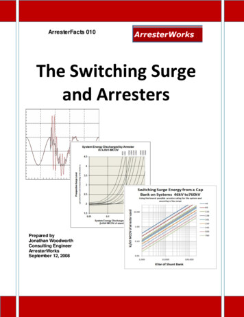
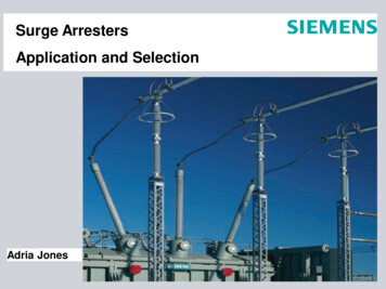
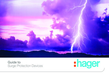
BS 7671 and the AQ criteriamethodLightning discharges could contain currents of 200,000Awhich if struck at or near power transmission lines wouldgenerate a significant voltage transient. This voltage transientcould cause significant damage to both domestic andcommercial electronic equipment.Average number of days ofthunder during the wholeyear (1971 to 2000)Average value (days) 1412 to 14The UK regional map illustrates the likely lightning activitycaused by the number of thunderstorm days across thecountry.10 to 128 to 106 to 84 to 6 4Protection against over-voltages is the subject of section 443of BS 7671. Here the AQ criteria method is introduced whichis based on the likelihood of the equipment being subjectedto over-voltages caused by lightning strikes, taking account ofthe probable number of lightning strikes per year.For electrical installations in the UK, the map shows that theprobable number of thunderstorm days per year in any givenlocation is less than 25, and therefore condition AQ1 applies.Map courtesy of the Met OfficeGuide to Surge Protection Devices5
Where this is the case and for installations being supplied byoverhead lines, Regulation 443.2.2 indicates that provided theimpulse withstand voltage of the equipment is not less thanthe values given in Table 44.3 (see Table 1 for installationsrated at 230 V to Earth), no additional protection by a SPD isrequired. However, where higher levels of equipment reliabilityor higher risks (e.g. fire) are expected, additional protection byan SPD against over-voltage may be required.Similarly, for an installation having no overhead lines, noadditional protection against overvoltages is required if theequipment meets the minimum voltage withstand values intable 44.3.There are some words of caution in the notes to this sectionwhere it is recognised that transient over-voltages transmittedby the supply distribution system are not significantlyattenuated. So an induced voltage some distance awaycould easily manifest itself at the electrical installation andcause potential harm to the equipment within. It is also worthconsidering that the AQ data is for thunderstorm days NOTlightning strikes. One storm will usually contain many lightningflashes which could lead to an over-voltage on the installationcausing damage to equipment.6“where higher levels of equipmentreliability or higher risks (e.g.fire) are expected, additionalprotection by an SPD againstover-voltage may be required.”Guide to Surge Protection Devices
Impulse withstandcategoryExample of equipment in category (note 1)I(low impulse voltage)Sensitive electronic equipment connected to the fixed installation.1.5 kVDomestic appliances and portable power tools connected to the fixed installation.2.5 kVIII(high impulse voltage)Equipment intended to be installed in a part of the fixed installation where a highdegree of availability of overvoltages is expected, such as distribution boards,circuit-breakers and wiring systems.4.0 kVIV(very high impulsevoltage)Equipment intended to be installed at or near the intake to the installation, suchas the energy meter.6.0 kVII(normal impulsevoltage)Required minimum impulsewithstand voltage (note 2)Table 1: Required minimum impulse withstand voltage for equipment where installation rated voltage is 230V to Earth (based on tables 44.344.4 of BS7671)Notes:1. Table 44.4 of BS 7671 gives a fuller list of examples of equipment falling into each category.2. This table applies only for installations of rated voltage (Uo) 230V. For installations of other rated voltages, see Table 44.3 of BS 7671.Guide to Surge Protection Devices7
Terminology & selection criteriaSurge protection devices are classified according to theirstandard into different typesIimp – Impulse current of 10/350 μs waveform associated withType 1 spd’s Type 1 - SPD which can discharge partial lightning currentwith a typical waveform 10/350 μs. Usually employs sparkgap technology.In – Surge current of 8/20 μs waveform associated with Type2 spd’s Type 2 - SPD which can prevent the spread of overvoltages in the electrical installations and protects equipmentconnected to it. It usually employs metal oxide varistor (MOV)technology and is characterized by an 8/20 μs current wave.Up - The residual voltage that is measured across the terminalof the SPD when In is appliedUc - The maximum voltage which may be continuouslyapplied to the SPD without it conducting Type 3 – These SPDs have a low discharge capacity. Theymust therefore only be installed as a supplement to Type 2SPD and in the vicinity of sensitive loads. Type 3 SPD’s arecharacterised by a combination of voltage waves (1.2/50 μs)and current waves (8/20 μs).8Guide to Surge Protection Devices
Selection of suitable devicesBS 7671 section 534 gives the requirements for correctselection of devices against overvoltages.Regulation 534.2.1 prescribes that where required by Section443 or otherwise specified, SPD’s shall be installed:(i)(ii)near the origin of an installation, orin the main distribution assembly nearest the originof an installationThe notes to this regulation give further guidance, stating thata Type 1 or a Type 2 SPD may be used at the origin whilstType 2 and Type 3 are also suited for locations close to theprotected equipment.In summary, a Type 1 SPD is used at the origin of theinstallation, a Type 2 SPD is used at distribution boards and aType 3 SPD is used near terminal equipment.Surge protection needs to be selected such that their voltageprotection level (Up) is lower than the impulse withstandcapability of the equipment to be protected. 534.2.3.1.1suggests that this value should be referred to category II ofTable 44.3. This for a 230/400V installation suggests thatthe value should not exceed 2.5kV. However 534.2.3.1.2suggests that to protect sensitive and critical equipment, thenconsideration should be given to reduce this value to thatrequired for category 1 equipment (ie 1.5kV).Type 1 SPD’s are often referred to as equipotential bondingSPD’s and are fitted at the origin. A lightning protectionsystem employing these devices only, offer no effectiveprotection against failure of sensitive electrical and electronicsystems. In order to achieve this, additional coordinateddevices will have to be employed.Guide to Surge Protection Devices9
534.2.3.4 also gives guidance as to the selection of anappropriate device.The specifier should ascertain from BS 7671 whichconnection type is preferable (CT 1 or CT 2). Hagermanufacture devices with connection type CT2.Type 1 devices need to be selected such that the valueof Iimp is not less than that which shall be calculated inaccordance with BS EN 62305-4. However if this cannot becalculated then this value shall be not less than 12.5kA. Also,due to the connection method, the value of Iimp between theneutral conductor and the protective conductor shall be notless than 50kA for three phase systems and 25kA for singlephase where the value cannot be calculated.“The specifier should ascertainfrom BS 7671 which connectiontype is preferable. Hagermanufacture devices withconnection type CT2.”For Type 2 devices the value of In shall be not less than 5kAand the value between the neutral and protective conductorshall be not less than 20kA for three phase systems and 10kAfor single phase. Larger values may be required as classifiedin BS EN 61643-11.10Guide to Surge Protection Devices
Guide to Surge Protection Devices11
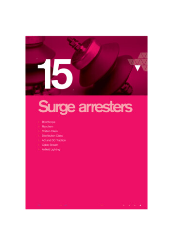
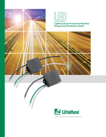
ConnectionTo gain maximum protection from the SPD, the connectingconductors should be kept as short as possible. This isto minimise any additive voltage drops on the connectingcables.OCPDaThe connecting conductors of the SPD shall have a crosssectional area of not less than 4mm2 copper and the totalconnecting lead length (a b) should preferably not exceed0.5m but shall in no case exceed 1m.SensitiveEquipmentSPDbWhere Type 1 devices have been installed the cross sectionarea shall be not less than 16mm2 copper. Manufacturer’sinstructions shall be followed.Some devices have dual line & neutral terminals. Thisconnection method reduces any additional voltage drop inthe connecting cables thereby obtaining the best possibleUp to the installation. There are conditions to this connectionmethod however. With Hager devices it is suitable forinstallations having a maximum demand up to 125A.12Main earthing terminal orconnecting conductor barOCPDSPD overcurrent protection device surge protection deviceGuide to Surge Protection Devices
of the RCD. Where this cannot be avoided, the RCD shouldbe of the time-delayed or S-type.OCPD 1L1L2L3Downstream CircuitsShould the distance between the SPD and the sensitiveequipment to be protected be greater than 10m, oscillationscould lead to higher voltage values appearing at theequipment. Consideration should be given to additionalcoordinated surge protection devices closer to theequipment. Again manufacturer’s instructions should befollowedProtective conductorProtection against SPD short circuits is often provided byan over-current protective device such as a fuse or circuitbreaker. This device must of course permit the flow of surgecurrent through the device without operating. Manufacturerswill give instructions as to which device is recommended.In certain circumstances this secondary over-current devicemay be omitted if the upstream over-current device meetscertain conditions.NOCPD 2SPDSPDSPDShould RCD’s be required in the installation as additionalprotection or to ensure the requirements of fault protectionare satisfied, then the SPD will need to be installed upstreamGuide to Surge Protection Devices13
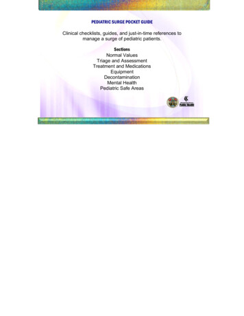
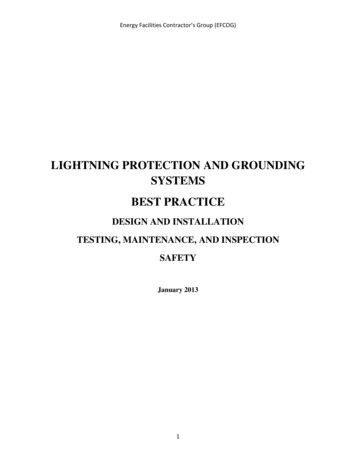
CascadingCascading is the term used to describe the method ofcombining several levels of surge protection devices into theone installation.This takes advantage of the best features of each deviceto improve the protection level for the equipment. Hagerrecommends using a high surge current capacity device todivert the bulk of the transient over-voltage at the origin ofthe installation.In the case of a Class 1 & 2 device this would be either thespark gap arrester or a high current capacity MOV. Shouldfiner protection be required, the next step is to install a Class3 device SP202N near the terminal equipment.“Cascading increases thecurrent diverting capacity of theSPD system whilst maintaininga low voltage (Up) to ensurethe best protection for valuableequipment.”Cascading increases the current diverting capacity of theSPD system whilst maintaining a low voltage (Up) to ensurethe best protection for valuable equipment.Selecting SPD of the same manufacturer or make will ensurecorrect co-ordination between devices14Guide to Surge Protection Devices
Incoming surgeMain protectionFine protectionExcess currentGuide to Surge Protection DevicesExcess currentNormal current flowallowing correct operation15
Inspection & TestingDuring the Initial Verification or as part of a periodicinspection & test, the SPD should be inspected to ensure itis operational. Any over-current protective device associatedwith the SPD should be intact and should be as instructed bythe manufacturer.There is usually some kind of visual indication on the SPDthat the device is still operational. This may be indicated by aGREEN visual indicator window. Should this window indicateRED then it is an indication that the device has reached its‘End of Life’ and needs replacing. With some products, thiswill involve the replacement of the device, but on many ofthe products in the range, this can simply be carried out byreplacing the removable cartridge.“There is usually some kind ofvisual indication on the SPD thatthe device is still operational.This may be indicated by a greenvisual indicator window.“An insulation resistance test of 500V dc carried out with theSPD connected will produce incorrect readings. This is dueto the SPD starting to conduct as the value of Uc may havebeen exceeded. This test then should be conducted withoutthe SPD connected. Alternatively this test can be conductedat the reduced test voltage of 250V dc.16Guide to Surge Protection Devices
SPD quick selection guideThe following is a quick selection guide which may assistin choosing whether SPD’s are required and the correcttype of device Does the installation contain a lightning protection system? Is the installation adjacent to any tall structure, tall trees ornear a hill top in a lightning prone area? Does the installation contain equipment where higherreliability from overvoltages is requiredIf the answer is YES in the above to the first two questions,it is recommended to install a Type 1 2 device. This willprovide protection against surges caused by direct lightningstrikes and provide protection against transient over-voltagescaused by indirect lightning strikes or by switching events.If the answer is YES to the third question then it isrecommended to install Type 2 devices to provide protectionagainst transient over-voltages caused by indirect lightningstrikes or by switching events.SPD decision flow chart for installationswithin the scope of this guideRisk of direct lightning(see BS EN 62305) orlightning protectionsystem installed?(443.1.1)YesOvervoltage protectionrequired. Install Type 1 or Type1 2SPDs at distributionboard/consumer unit toprevent dangerous flashover(534.2.1)NoOverhead linesupplying the buildingat risk of direct strike see BS EN 62305(443.1.1)NoInstallation presentshigher risk (e.g. fire) orrequires higher reliability fromovervoltages including switching(443.2.2 Note) - see BS EN62305.YesYesNoCo-ordinated set ofovervoltage SPDs forequipment protection e.g.Type 2 or Type 2 3 fordistribution boards feedingsensitive electronic equipment(534.2.6).Protection against overvoltageis not required (443.1.1,443.2.2) if equipment impulsewithstand voltage to Table44.3Note: For larger installations beyond the scope of this guide, a risk assessment methodused to evaluate the need for SPDs is given in Section 443 of BS 7671:2008(2011)Guide to Surge Protection Devices17
Benefits of using Hager SPD’s All applications are covered with a full range of compatibledevices. Protection for high rise towers; commercialbuildings with essential computer data and expensiveoffice machinery; domestic dwellings with entertainmentand computer systems. Advanced warning that the device needs replacing.Remote indication option means an audible or visible alarmcan warn the user that the cartridge needs replacing.“Remote indication option meansan audible or visible alarm canwarn the user that the cartridgeneeds replacing.”Product configuration Thermal and dynamic disconnectionIncreases equipment life (by providing clean power)DIN mounted devicesRemovable tabs on replaceable cartridges to give thecontractor the option of allowing the consumer to replacethe cartridge IP20 Does not disconnect your installation from supply whenexperiencing a transient over-voltage Conforms to BS EN 62305-2 BS / EN 62305-3 / BS EN61643-1118Guide to Surge Protection Devices
Type 1 2 (Combined in a single device) (with lifetime 4N-PEUpkVUc VWidth(mm)Singleor ThreephaseTNSTNC-STTCat. Ref.(withremotecontact)-- 1.5255 V ac35SinglePPPSPA201-50-- 1.5255 V ac70ThreePPPSPA401-25100-- 1.5255 V ac140ThreePPOSPN801SPN801R25100-- 1.5255 V ac140ThreeOOPSPN802SPN802RClass 2 (with lifetime indicator)2--515 1.2275 V ac35SinglePPPSPN215DSPN215R2--1540 1.5275 V ac35SinglePPPSPN240DSPN240R4--515 1.5275 V ac70ThreePPPSPN415DSPN415R4--1540 1.5275 V ac70ThreePPPSPN440DSPN440R 1.5255 V ac35SinglePPPSP202N- 41000 V dc52.5----SPV325-SinglePPPVA02SPD-Class 3 (fine protection) (with lifetime indicator)2--3-PV Applications (dc side) (with lifetime indicator)3--12.525Consumer Unit Kit Type 2 SPD Kit with SPN215D (with lifetime indicator)2--515 1.2275 V ac35Guide to Surge Protection Devices19
Hager Ltd.Hortonwood 50TelfordShropshireTF1 7FTInternal Sales Hotline: 01952 675612Internal Sales Faxline: 01952 675645Hager Ltd.Unit M2Furry Park Industrial EstateSwords RoadSantryDublin 9IrelandNorthern Ireland Tel: 028 9077 3310Northern Ireland Fax: 028 9073 3572Technical Helpline: 01952 675689Technical Faxline: 01952 er.co.ukGUIDESPD516Republic of Ireland Tel: 1890 551 502Republic of Ireland Fax: 1890 551 503www.hager.ie
OCPD SPD a b Sensitive Equipment Main earthing terminal or connecting conductor bar OCPD overcurrent protection device SPD surge protection device. Guide to Surge Protection Devices 13 Should the distance between the SPD and the sensitive eq