Transcription
Balancing BasicsMike Weisman, ASHRAE TreasurerASHRAE Golf Outing: May 18th, 2018! HEATHERWOODE
Agenda: Why balance?Manual Balancing ValvesManual Balancing ProcessAutomatic Flow ControllersPartial Load Conditions: Hydraulic InteractivityPressure Independent Control Valves
Two Reasons for Balancing1.Comfort 2.Satisfying Flow RequirementsDelta T Realization Optimize Coil PerformanceEliminate Overflow – Partial Load ConditionMore efficient equipment, less required pump heat
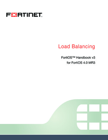
Hydronic HeatingAir InTerminal180 HWSTerminalTerminalEnergy (Heat) isproduced at a centrallocation anddistributed to variouslocations via water140 TerminalHWRBoilerAir Out
Why Balance? Without balancing, the circuits closest to thepump would overflow and those further awayunderflow “I don’t need balancing valves! The controlvalves will throttle the flow.”
Balancing BasicsSimplified building schematicEach leg has 5’ of resistanceThe lowest terminal has 20’ ofresistance, the furthest has 0’Terminal210gpm13gpm7gpm5’ 10’5’Different resistances causediffering flowsBy adding manual balancingvalves,we can equal out all theresistances and thereforeall the ��5’5’
Why Balance?
Manual Balancing Valves
𝑸 𝑪𝒗 𝑷
Manual Balancing Valves Calibrated Orifice vs. fixed orifice(Venturi) Ball, Globe, Butterfly Accuracy Precision Typically Balancing AND Shut Off
Manual Balancing ProcessLifts, Ladders, Drop Ceilings, Furniture
Proportional Balancing Set valves to the correctratio, they will all be in thesame % of overflow orunderflow Balance each sectionwithin itself Use partner valve tobalance sections pm2gpm8gpm8gpm8gpm
Splitting into Hydronic Modules
Balancing a Module
Hydraulic Interactivity
Balancing a Module
Balancing a Module
Balancing a Module
Order for Balancing Modules
Full Pump Heat, Valves Wide Open
Proportional Branches
Balance All Partner Valves
Optimize Pump Head
Manual Balancing Reality—Infinite Solutions
Automatic Flow Controllers
Automatic Flow Controllers “Flow Limiter”: A bit of a misnomer. Full Flow, Whether you need it or not Pressure-Independent Balancing Valve Select cartridge based on design flow Install It, Check Pressure, Forget About It Still NEED Partner Valves! Operating Range (Typical): 2-32psi dPCartridge Design Benefits Maintains 5% accuracy of design flowTerminals can be flushed with cartridge in place Reduced commissioning timeSimple selection and identification of flow rateCan be fitted adjacent to bend or fitting in pipe
Automatic Flow Controllers
Automatic Flow Controllers𝑸 𝑪𝒗 𝑷 Flow is constant within operating dP range The Cv of the cartridge adapts to the dP withinthe operating range to provide constant designflow
Partial Load Conditions
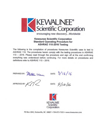
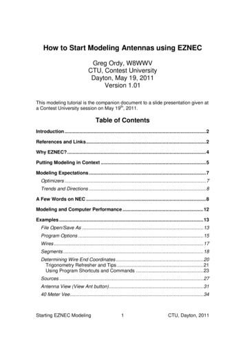
% of heating seasonbelow this loadDifferential pressure variations58%HeatingDp pipingPower120%100%100%80%80%Thermal plant load [%]50 %loadDallas% of cooling seasonbelow this load P q 2Thermal plant load [%]60%60%40%40%4% press.drop 0%20%20%0%0%50%100%150%200%0%20% 40% 60% 80% 100%FlowAt constant supplywater temperature68%CoolingApril 2010Flow20 %flowPressure drops are reducedto 4% of their design value.32
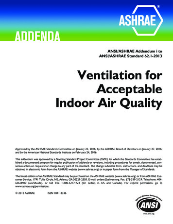
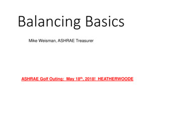
Control loopSet value UDisturbancesControllerSensorxk1x U-xk2ActuatorSignal0 - 10 utputRoom0-100%xx controlled value100PoweroutputHeatoutputin %%100Flowinin%Flow%PoweroutputHeatoutputin %%100909090808080707070606060 50 5050404030303020202010Flow in %00 10 20 30 40 50 60 70 80 90 100Terminal unit characteristicApril 2010100Lift h in %0 10 20 30 40 50 60 70 80 90 10040100Lift h in %0 10 20 30 40 50 60 70 80 90 100Control valve characteristic33
Manual m17gpmTerminals are set to 10gpm with staticWhenAsotheroneterminalscontrol valvetry to closesmodulate,down,valves.all controlvalves areAsmoreWhenportionsof the buildingthe other situationoverflowterminalsintensifies,overflow, wastingopen, systemis comfortable&close,the situationgets worseenergyincreasingenergy costsefficient All circuits are interactive dP sensor placement is critical
Overflow Low ΔT180 15gpm10gpm20gpmDesign:10GPM,40 ΔT170 160 140
Overflow Effects on Coils Coils are designed to flow a certainamount Over 100% flow, the efficiency of thecoil reduces 150% flow 110% heat 250% flow 120% 0%120% 140% 160% 180% 200%220%240%
Autoflow Valve with Modulating Control Valve In partial loads, a control valve will start to close (decrease Cv) As the control valve modulates, the automatic balancing cartridge will tryto maintain design flow (increase Cv) Eventually the control valve will decrease available head pressure enoughto modulate flow Also contributes to the same low delta T syndrome.𝑸 𝑪𝒗 𝑷
Control Valve Authority with anAutomatic Balancing ValveRequired Flow2.5gpm10gpm5gpm7.5gpmActual Flow5gpm10gpm
Manual Valves: Pros and Cons PROS Performs well with a modulating control valve Flexible for changes to the space/water quality With proper balancing, can decrease pump head CONS Labor intensive balancing process/commissioning Very dependent on quality of the balancing contractor Susceptible to overflow situations
Automatic Valves: Pros and Cons PROS ONE pass balancing ELIMINATES interactivity in the system Eliminates overflow situations CONS “Fighting” with modulating control valves Cartridges have tiny openings: Higher pressure drop, susceptible to clogging Is the correct cartridge installed?
Best of Both Options? Pressure Independent, Balancing Control Valves Two valves in one: Balancing Valve, Control Valve with Pressure RegulatorPressure drop across the valve seat is fixedVery precise modulation!Actuator technology can simplify balancing processBe aware of minimum start pressure! Up to 5 psi for smallest valves!𝑸 𝑪𝒗 𝑷
Control loopSet value UDisturbancesControllerSensorxk1x U-xk2ActuatorSignal0 - 10 utputRoom0-100%xx controlled value100PoweroutputHeatoutputin %%100Flowinin%Flow%PoweroutputHeatoutputin %%100909090808080707070606060 50 5050404030303020202010Flow in %00 10 20 30 40 50 60 70 80 90 100Terminal unit characteristicApril 2010100Lift h in %0 10 20 30 40 50 60 70 80 90 10040100Lift h in %0 10 20 30 40 50 60 70 80 90 100Control valve characteristic42
Autoflow vs. PICVAlways be able to verify flow!
Applications . ON/OFF Control: Chilled beam, fin tubes, WSHP, UH Automatic flow controller Modulating Control: FCU, VAV, above 1 GPM Manual balancing valve Systems with lots of diversity in loads, fluctuating dP Automatic flow controller, PICV Large Flows (AHUs), Precise discharge air temp. PICV Retrofits, Expansions PICV
Final Thoughts Follow the pressure, not the flow 1-2 degree change in operating conditions can have a HUGE impact onsystem performance! One solution doesn’t fit every application! The more balancing shutoff valves, the better!
Questions?
ASHRAE Golf Outing: May 18th, 2018! HEATHERWOODE. Agenda: Why balance? Manual Balancing Valves Manual Balancing Process Automatic Flow Controllers Partial Load Conditions: Hydraulic Interactivity Pressure Indepen