Transcription
Computer-aided design and analysis of arch damsSalazar F.1, San Mauro, J.1, Vicente D.J.1, Baena, C.M.2, Granell, C.2, Gracia, L.1 dePouplana, I.1 and Oñate, E.11International Center for Numerical Methods in Engineering (CIMNE), Barcelona, SPAIN2Jesús Granell Ingenieros Consultores, SL, Madrid, SPAINE-mail: fsalazar@cimne.upc.eduABSTRACT: Double curvature arch dams feature geometrical complexity with a significant amountof parameters involved. Different criteria exist to assist in the design task, from simplified geometricalapproaches to optimization procedures. However, most of them present a lack of flexibility and are notintegrated in computer-aided design tools.In this contribution, an interactive and flexible software tool is presented to support the completedesign process: geometrical definition, FEM model generation (including the mesh, the loads and theboundary conditions) and thermo-mechanical analysis.The design can be performed with different levels of detail to adapt to the information available ineach stage of the project. The tool allows defining the shape of the reference cylinder, the excavationdepth and slope along the foundation, the crown cantilever thickness and curvature, the shape andlocation of horizontal arcs; all these steps were described in former contributions. Here, specialattention is paid to the introduction of additional features such as joints, spillways, abutments ofvarying shape and outlet works. All steps have been defined with a high degree of flexibility in thedesign process.The tool is integrated with the pre and post process software GiD, which allows taking advantage of itsfunctionalities, such as mesh generation and results analysis. It is also coupled with a specificapplication for thermo-mechanical analysis of dams, developed in Kratos Multiphysics – a frameworkfor building parallel multi-disciplinary simulation software. The whole design process can be followedin a unique environment, because the structural response of preliminary designs can be computed andthe results considered to refine the dam geometry.1 IntroductionArch dams are more efficient than other typologies in terms of structural behavior. Unlikegravity or rock fill dams, which resist the hydrostatic load mostly by means of their weight,arch dams distribute part of the load to the abutments, which allows reducing the necessaryvolume of concrete.This higher efficiency implies a greater complexity: On the one hand, their structuralverification requires three-dimensional models, and on the other, their design is morecomplicated. The development of the finite element method (FEM) allowed performing theirstructural analysis, which can be done with different software tools. However, designcontinues to be fundamentally based on rules of good practice and past experience, a processthat is clearly susceptible to improvement.Reference documents in engineering practice contain useful design criteria [1], [2], thoughthey do not take advantage of the possibilities of computer-aided design. Recently, the UnitedStates Bureau of Reclamation (USBR) has published a design manual including a spreadsheetfor a simplified design [3], but it can only be applied to dams with circular axe.The topic aroused interest of the community: Goulas [4] presented an application to assist inthe design of arch dams compatible with the FEM code DIANA [5].
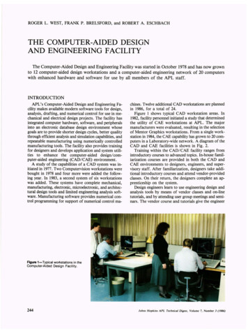
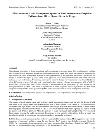
In this context, we are working on a software tool for automatizing the whole process ofdesign and verification of double-curvature arch dams. It includes functionalities for definingthe geometry in an interactive way. It is integrated in the pre and post process software GID[6] and coupled to “DamApp”, an in-house developed code for thermo-mechanicalcomputation of dams. The latter is one of the applications of the open-source environmentKratos Multiphysics [7], [8], which has been previously employed for the structural analysisof arch dams [9], [10], [11]. Once the FEM model has been created and the calculationperformed, the design can be modified in view of the results and the process repeated until theproblem constraints are fulfilled.The first version of the application was described in a previous work [12]. Here, we brieflydescribe the most relevant features and present some new functionalities implemented. Theycorrespond to additional features such as monolithic joints, spillways, abutments of varyingshape and outlet works.2 Methods2.1 Model geometryAs mentioned before, the tool is integrated in the software GID. Once the topography of thedam site has been loaded, the main steps to be followed are:1. Definition of the elevation of (a) crest and (b) lowest point in the foundation.2. Selection of the guideline curve for the reference cylinder. In the current version, it can beeither a parabola or an ellipse. It should be noted that most circular arcs can beapproximated with ellipses with enough accuracy, if necessary.3. Introduction of the excavation depth, which can be different for different sectors of thefoundation.4. Generation of the reference cylinder and computation of its intersection with the groundtopography5. Definition of the crown cantilever. Initially, the preliminary design proposed by the USBR[3] is drawn; it can be modified afterwards.6. Selection of lines of centers for the curves defining the upstream and downstream faces atten equally spaced elevations between crest and foundation.7. Generation of the arcs for each elevation and dam face (intrados and extrados).8. Creation of the dam body in 3D.9. Selection of the excavation slopes for each margin and for the river bed.10. Adjustment of the overhanging, if appropriate.11. Definition and generation of additional features, if applicable: Monolith joints Abutment blocks Spillway Outlet works12. Mesh generationThe main window of the interface is depicted in Figure 1. The example corresponds to aparabolic fit. Schemes to assist to the definition of the excavation depth and the lines ofcenters can be activated by the user. In the example, the first is shown.
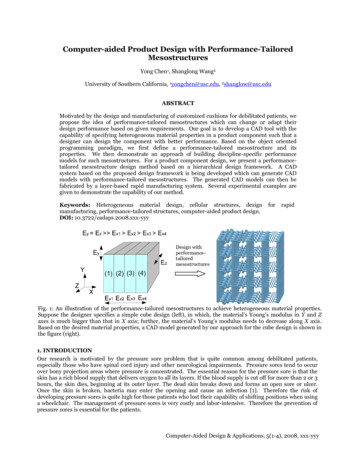
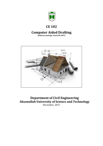
Figure1: Interface off the application. Mainn window.At the eend of the process, a 3D finite eelement model is generated, whicch can be useduin athermo--mechanicall analysis. FigureF2 shhows an exaample, wherre the spillwway, abutmments andexcavattion can be observed.oEof 33D model generatedgwithw the tool.Figure 2: Example
Some features such as spillways or bottom outlets works, whose influence in the structuralresponse is typically minor, are optional and can be neglected in preliminary studies.It is worth noting that the final FEM model can be modified from the GID interface, as anordinary model. Each element of the model geometry can be tuned, as well as the meshproperties, domain dimensions, etc. Nonetheless, a preliminary fit can be done and computedby users unfamiliar with GID or any other pre-process software.2.2 Thermo-mechanical analysisThe tool is also integrated into “DamApp”, an application for thermo-mechanical analysis thatincludes specific features for dam engineering:1. Seismic analysis can be performed, including hydrodynamic effects, which can beconsidered by means of the Westergaard formula [13] or by fluid-structure interaction(FSI) [14].2. Modal analysis is available to obtain the natural frequencies.3. Joints between cantilevers (or blocks in gravity dams) can be accounted for via jointelements, which can reproduce their nonlinear behavior. They are governed by a cohesivebilinear law [15], [16].4. Nonlinear constitutive models can be used to account for damage.5. Transient loads and boundary conditions can be applied6. Sub-pressure and uplift can be considered, together with the effect of drainage.7. Variable water temperature, both in time and depth, can be accounted for, including thevariation in the water surface elevation along time. Both the Bofang formula [17] and auser-defined one can be employed.8. The construction process can be reproduced by activating layers along the transientcalculation.9. Stresses in global coordinates can be transformed into principal stresses(tensile/compressive) for a more intuitive interpretation of the results.10. The results of the numerical model and the monitoring data can be jointly analyzed: theuser can define the location and nature of the monitoring devices, which results are writteninto specific files.2.3 New functionalities in the geometry generation processAs mentioned before, the main aspects of the geometry generation process were described indepth in a previous work [12]. In this section, we focus on the new functionalitiesimplemented, which allow including additional elements such as joints, abutment blocks,spillways and outlets works. The parameters involved in the definition of these elements arelisted in Table 1.Table 1: Geometrical parameters of dam elementsElementMonolith jointsAbutment blocksParameterCantilever thicknessLocationLocationTransition lengthDownstreamthicknessDownstream -Right sidewallLocation-Left sidewallOgee crest eterOdOutlet works
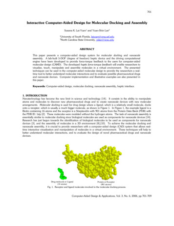
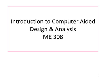
The loccation of eacch element is defined iin terms of the distance along damm axis to thhe vertexof the guideline currve of the reeference cyllinder (O), as depicted in Figure 33.JointsThe possition of thee vertical jooints is deterrmined by thet width of the cantileevers (Jth), which isfrequenntly constannt along thee dam axis. This valuee can be inttroduced inn the corresspondingwindoww. With this procedure, a joint coinncides withh the vertex O, and the remaining ones areevenly sspaced towaards both abbutments.If somee cantilever features diifferent widdth, the loccation of the corresponnding jointss can beintroducced manually defining their distannce to the vertexvO (Jx).) Figure 3 shows the interfaceifor definning the joints with thee ‘automaticc’ or ‘manual’ options.Figuree 3. User intterface to inntroduce thee location off the monoliith joints. TThey are deffined interms of theirtdistancce to the verrtex along thhe axis of thhe referencee cylinder.Abutmeent blocksMany aarch dams transmittparrt of the loaads to the marginsmthrrough a speecial structuure, withhigher wwidth, also termed “arrtificial abuttment”. Thiis reduces thet maximuum stress appplied tothe founndation, heence favors a smooth distributionn of stress. A proceduure to definne theseelementts is also immplementedd in the desiign tool. Inn this versioon, four parrameters neeed to bedefined: (a) distancce to the veertex (Ax) ((which definnes the starrt of the bloock), (b) traansitionslength (Atl), (c) dowwnstream thhickness (Atth) and (d) downstreamdslope (Ads) .The geoometrical coonstruction follows the following processp(seee Figure 4):1. The point A in the upstreaam face of tthe dam, whhere the abuutment startrts, is fixed with thedistaance Ax.2. The segment ABA is definedd by placingg the transittion length Atl along a pperpendicullar to thegh A.axiss of symmettry of the reference cyliinder throug3. The symmetriccal segment to AB withh respect to the tangent to the extrrados at A isi drawnand moved fromm A to C, tuurning into CD .ular to the orriginal end of the abutmment.4. BE and DF are perpendicu
5. The thickness can be inncremented by turningg DF towaard downstrream an angle Athobtaaining the point G.6. The downstreamm slope cann be modifieed with the parameter Ads.gure 5 showws the interrface of the tool forEach abbutment bloock can be defined sepparately. Figintroduccing the parrameters of the abutmennt blocks.Figuree 4. Elements involved in the definnition of thee abutment bblocks.Fiigure 5. Inteerface of thee tool to deffine the abuutment blockks.
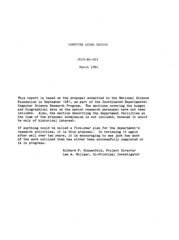
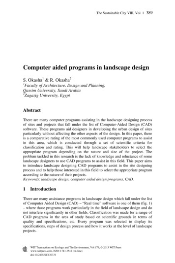
Spillwaays and outtlet worksThe appplication allows designing a ‘spillwway crest’ located,las its name sugggest, at thee crest ofthe damm. As the eleements desccribed in thhe previous sections, it is defined ttaking the vertexvofthe guiddeline curvee as a reference. Hence , the distancces to the leeft (Sls) and right (Srs) sidewallssof each spillways bayb need too be introduuced, as weell as the heeight (Sh) – difference betweendam creest elevationn and that ofo the spillwway crest (FFigure 6). TheT processs can be reppeated tointroducce several sppillway bayys.Figure 6. DefinitionDoff crest spillwway and botttom outletss.Outlet wworks can be defined in a similaar way, i.e., as many elements aas necessaryy can beintroducced by meaans of 3 geoometrical paarameters: thet locationn of the axiis with resppect to O(Ox), itss elevation (O( e) and diaameter (Od) (Figure 6).3 Exxample ofo appliccationThe appplication haas already beenbused too generate several 3D models of Spanish arch dams[12]. Inn engineerinng practice, 3D numeriical models of existingg dams needd to be creaated withcertain frequency,, to make additionall studies (in( case ofo dam heiightening, updatedcthe geeometry neeeds to beregulations, changee in dam operation rulees [18], etc.)). In these cases,construccted in 3D from 2D drrawings (topp, side and front viewss). The convventional prrocedureconsistss in digitizinng each crooss section, putting theem in their correspondding locationn in 3D,and gennerating voluumes for eaach cantilev er. This taskk is cumberrsome and ccan be autommated.work, the neew functionnalities pressented were applied to build a 3D model of LaL BaellsIn this wdam. It is a 102-m height archh dam locateed in the Lllobregat Rivver, in Barccelona, Spaiin. It hasbeen ussed as case study in previouspwoorks ([19], [20]), whicch include descriptionns of thestructurre and its peerformance.
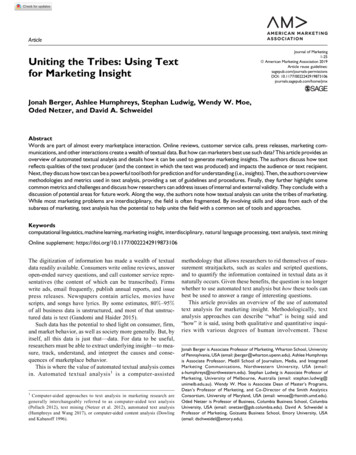
Figure 7 shows severalsviewws of the resulting model,mhighhlighting thhe monolithh joints,abutmennt blocks, outletoworks and mesh.del for La BBaells dam. Top:Tview fromfdownsstream. Botttom left:Figure 7. Resultingg FEM modbutment, whhere the exccavation cann be observeed, as well as thedetailed view off the right abfinite ellement meshh. Bottom right:rView from the left abutmentt, showing ththe spillwayy and theooutlet workss.4 Suummary,, conclussions andd currennt workAn appllication has been preseented to assiist in the deesign processs and strucctural verificcation ofarch daams. The usser can defifine the geoometry of thhe model accordingatoo the rules of goodpracticee, previous experienceeanda the geoometry of thhe canyon.A finitee element meshmcan bee directly geenerated froom the resuulting geommetry, whichh in turncan be eemployed too run thermmo-mechaniccal analysess. In view ofo the resultss, the design can bemodifieed, if necesssary. The FEEM computtation is performed byy means of ““Dam App””, one ofthe appplications developeddinn the Kratoos environmment, a fraamework foor building parallelmulti-diisciplinary simulation software. NNonethelesss, the modeel could alsoo be analyzzed withother soolvers, thankks to the fleexibility of GGiD [6].
The parametric definition of specific elements of arch dams, such as joints, abutmentsspillways and outlet works, will help to create FEM detailed models in a straightforward way.It can also reduce the possibility of introducing mistakes in the design, or while building aFEM model of an existing dam.Some of the processes were developed following determined design criteria, such as the shapeof the abutment blocks or the geometry of the dam faces. We are currently working in theimplementation of additional options, to increase the flexibility of the design process.Nonetheless, it should be noted that the resulting model can be fully modified by the user bymeans of the pre-process tools included in GiD.The Dam App is also under development. The upcoming functionalities include the detailedconsideration of the construction process and the boundary conditions, among others.5 AcknowledgementsWe acknowledge the financial support to CIMNE via the CERCA Programme/Generalitat deCatalunya. The research was also supported by the Spanish Ministry of Economy andCompetitiveness (Ministerio de Economía y Competitividad, MINECO) through the projectsACOMBO (RTC-2015-3794-5) and NUMA (RTC-2016-4859-5).6 References[1] USACE – US Army Corps of Engineers, editor (1994). Arch Dam Design, USACE,Washington DC, USA.[2] USBR – US Bureau of Reclamation, editor (1977). Design Criteria for Arch and GravityDams – Engineering Monograph Nº19. US Government Printing Office, Denver,Colorado, USA.[3] USBR – US Bureau of Reclamation, editor (2013). Design of Double-Curvature ArchDams Planning, Appraisal, Feasability Level. Technical Memorandum No. EM36-8668110.[4] Goulas, E. (2016). Design of Double-Curvature Arch Dams in Terms of Geometric andStress Constraints by Using Script-Based Finite Element Modelling. Master Thesis. DelftUniversity of Technology. uuid:2c07c294-ece4-4bb3-8ec1-1bda6b3d8289.[5] DIANA 9 (Displacement Analyzer), Users manual. Release 9. The Delft (TheNetherlands): TNO Diana Inc.[6] GiD the personal pre and post processor. http://www.gidhome.com/, June 2017.[7] Kratos Multiphyisics. http://www.cimne.com/kratos/, June 2017.[8] Dadvand, P., Rossi, R., and Oñate, E. (2010). “An Object-oriented Environment forDeveloping Finite Element Codes for Multi-disciplinary Applications”. Archives ofComputational Methods in Engineering. 17, 253–297.[9] Salazar, F., Toledo, M. Á., González, J. M., and Oñate, E. (2017) Early detection ofanomalies in dam performance: A methodology based on boosted regression trees. Struct.Control Health Monit., doi: 10.1002/stc.2012.[10] de-Pouplana I., Gracia L., Salazar F. and Oñate, E. (2017) Cracking of a concrete archdam due to seasonal temperature variations. 14th International Benchmark Workshop onthe Numerical Analysis of Dams. Stockholm, Sweden, Sept. 2017[11] Gracia L., de-Pouplana I., Salazar F. and Oñate, E. (2017) Static and Seismic Analysis ofthe Janneh Arch-gravity Dam. 14th International Benchmark Workshop on the NumericalAnalysis of Dams. Stockholm, Sweden, Sept. 2017
[12] Vicente, D.J., San Mauro, J., Salazar, F. and Baena, C.M. (2017). An Interactive Tool forAutomatic Predimensioning and Numerical Modeling of Arch Dams. MathematicalProblems in Engineering, vol. 2017, Article ID 9856938, doi:10.1155/2017/9856938.[13] Westergaard H. M. (1933) Water Pressure on Dams during Earthquakes. Transactions,ASCE, Vol. 98, 418-472.[14] Zienkiewicz, O. C., Taylor, R. L., & Taylor, R. L. (1977). The finite element method(Vol. 1). London: McGraw-hill.[15] Camacho G. T. and Ortiz M. (1996) Computational modelling of impact damage in brittlematerials. International Journal of Solids and Structures, 33(20):2899–2938.[16] Song S. H., Paulino G. H. and Buttlar W. G. (2006). A bilinear cohesive zone modeltailored for fracture of asphalt concrete considering viscoelastic bulk material.Engineering Fracture Mechanics, 73(18):2829–2848.[17] Bofang, Z. (1997). Prediction water temperature in deep reservoirs. Dam Eng., 8(1), 13–25.[18] Suárez, B., Miquel, J., González, J. M., Barbu, L. G., Buil, J. M., Rio, J. F., and Batlle,M. T. (2013). The behavior of Baserca and Llauset dams in the new energetic scenarios.In Proceedings: 9th ICOLD European Club Symposium: sharing experience for safe andsustainable water storage, 10-12 April 2013, Venice, Italy (pp. 144-144).[19] Salazar, F., Toledo, M. Á., Oñate, E., & Suárez, B. (2016). Interpretation of damdeformation and leakage with boosted regression trees. Engineering Structures, 119, 230251.[20] Salazar, F., Toledo, M. A., Oñate, E., & Morán, R. (2015). An empirical comparison ofmachine learning techniques for dam behaviour modelling. Structural Safety, 56, 9-17.
integrated in computer-aided design tools. In this contribution, an interactive and flexible software tool is presented to support the complete design process: geometrical definition, FEM model generation (including the mesh, the loads and