Transcription
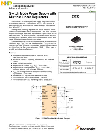
Data sheetPower supply CP-E 24/10.0Primary switch mode power supply2CDC 271 028 F0008The CP-E range offers enhanced functionalitywhile the number of different types has beenconsiderably reduced. Now all power supply unitscan be operated at an ambient temperature of upto 70 C.Characteristics–– Rated output voltage 24 V DC–– Output voltage adjustable via front‑face rotarypotentiometer “OUTPUT Adjust”–– Rated output current 10 A–– Rated output power 240 W–– Supply range 115/230 V AC (90-132 V AC,180-264 V AC, 210-375 V DC), auto select–– Typical efficiency of 89 %–– Low power dissipation and low heating–– Free convection cooling (no forced cooling with ventilators)–– Ambient temperature range during operation ‑40. 70 C–– Open‑circuit, overload and short‑circuit stable–– Integrated input fuse–– Redundancy unit CP‑A RU offering true redundancy,available as accessory–– Signalling contact “13-14” (solid-state) for output voltage OK–– LEDs for status indicationApprovalsA UL 508, CAN/CSA C22.2 No.107.1 1)HANSI/ISA‑12.12, CAN/CSA C22.2 No. 213(Class I, Div. 2, hazardous locations)HUL 60950, CAN/CSA C22.2 No.60950 1)REEAC1)CCC 1)Approval refers to rated input voltage UinMarksa CEbRCMOrder dataTypeInput voltage rangeRated output voltage / currentOrder codeCP-E 24/10.090-132 V AC / 180-264 V AC24 V DC / 10 A1SVR 427 035 R0000210-375 V DCOrder data – accessoriesTypeDescriptionOrder codeCP‑A RURedundancy unit1SVR 427 071 R0000The CP‑A RU provides decoupling of two CP‑E power supply units 40 V and 5 A.
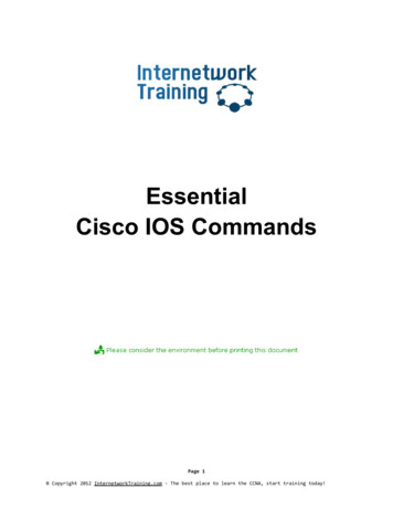
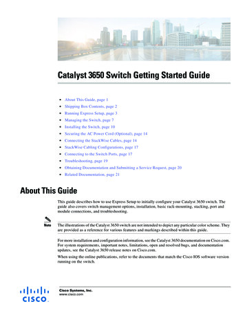
Functions1 OUTPUT L , L , L-, L-:terminals – output312 INPUT L, N, PE:terminals – input764583 13-14:terminals – signalling contact4 OUTPUT LOW:red LED – output voltage too low5 OUTPUT OK:green LED – output voltage OK26 OUTPUT Adjust:potentiometer – adjustment of the output voltage7 single/parallel:sliding switch – adjustment of single or parallel operation8 Circuit diagramApplicationThe primary switch mode power supply offers two voltage input ranges. This enables the supply with AC or DC.Furthermore it is equipped with two generous capacitors, which ensure mains buffering of at least 30 ms (at 230 V AC).That is why the devices can be used worldwide also in high fluctuating networks and battery‑powered plants.Operating modeBy means of the potentiometer “OUTPUT Adjust” the output voltage can be adjusted within a range of 22.5 to 28.5 V DC.Thus, the power supply can be optimally adapted to the application, e.g. compensating the voltage drop caused by a longline length.The green LED “OUTPUT OK” is lightening during proper operation.The red LED “OUTPUT LOW” is lightening when the output voltage is too low.Switch “single/parallel” for selection of single or parallel operation.Signalling contact 13-14 (max. 60 V DC / 0.3 A) is ON when the output voltage is more than 75 %.2 - Power supply CP-E 24/10.0 Data sheet
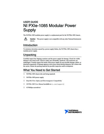
InstallationMounting2CDC272017F0b082CDC 272 017 F0b08The switch mode power supply can be snapped on a DIN rail according to IEC/EN 60715 as shown in the accompanyingpicture. For that the device is set with its mounting rail slide on the upper edge of the mounting rail and locked by lifting itdownwards.Demounting2CDC272018F0b082CDC 272 018 F0b08Remove the switch mode power supply as shown in the accompanying picture. For that the latching lever is pulleddownwards by means of the screwdriver. Alternatively you can press the unlock button to release the device. Then in bothcases the device can be unhinged from the mounting rail edge and removed.Mounting position2CDC 272 020 F0b082CDC272020F0b08The devices have to be mounted horizontally with the input terminals on the b ottom. In order to ensure a sufficientconvection, the minimum distance to other modules should not be less than 25 mm in vertical and horizontal direction.Data sheet Power supply CP-E 24/10.0 - 3
Electrical connectionConnect the input terminals L and N. The protective earth conductor PE must be connected. The i nstallation must beexecuted acc. to EN 60950, provide a suitable disconnecting device (e. g. line protection switch) in the supply line. Theinput side is protected by an internal input fuse.Rate the lines for the maximum output current (considering the short‑circuit current) or provide a s eparate fuse protection.We recommend to choose the cable section as large as possible in order to minimize voltage drops. Observe the polarity.The device is overload, short‑circuit and open‑circuit proof. The secondary side of the power supply unit is electricallyisolated from the input and internally not earthed (SELV) and can therefore be earthed by the user according to the needswith L or L‑ (PELV).Connection diagramNL PWML-PEPENL2CDC272023F0b08L2CDC 272 023 F0b08L- L- L L 13 144 - Power supply CP-E 24/10.0 Data sheetL , L‑Output voltageL, NInput voltage13-14Signalling contact foroutput voltage OKPEProtective earth
Safety instructions and warningsThe device must be installed by qualified persons only and in accordance with the specific national r egulations (e.g., VDE,etc.). The devices are maintenance-free chassis-mounted units.Disconnect system from supply network!Before any installation, maintenance or modification work: Disconnect the system from the supply n etworkand protect against switching on.Before start of operation:Attention! Improper installation/operation may impair safety and cause operational difficulties or d estructionof the unit. Before operation the following must be ensured:––Connect to main according to the specific national regulations.––Power supply cables and unit must be sufficiently fused. A disconnecting device has to be provided forthe power supply to disengage unit and supply cables from supply mains if required.––The protective earth conductor must be connected to the terminal PE (Protection class I)––The secondary side of the power supply unit is not earthed and can be earthed by the user according tothe needs with L or L-.––Rate the output lines for the output current of the power supply and connect them with the correctpolarity.––In order to ensure sufficient air-cooling the distance to other devices has to be considered.In operation:––Do not modify the installation (primary and secondary side)! High current! Risk of electric arcs andelectric shocks (danger to life)!––Risk of burns: Depending on the operation conditions the enclosure can become very hot.––The internal fuse is not user-replaceable. If the internal fuse blows, most probably the device is defective.In this case, an examination of the switch mode power supply by the manufacturer is necessary.Attention! High voltage! Danger to life!The power supplies contain components with high stored energy and circuits with high voltage! Do notintroduce any objects into the unit, and do not open the unit. With some units of this range the o utput iscapable of providing hazardous energy. Ensure that the service personnel is protected against i nadvertentcontact with parts carrying energy.Data sheet Power supply CP-E 24/10.0 - 5
Technical dataData at Ta 25 C, Uin 230 V AC and rated values, unless otherwise indicatedInput circuitsSupply circuitsRated input voltage UinL,N115 / 230 V ACInput voltage rangeAC90-132 V, 180-264 VDC210-375 VAC47-63 Hzauto selectFrequency rangeTypical input currentat 115 V AC4Aat 230 V AC1.55 ATypical power consumption270 WInrush current limitingDischarge currentat 115 V AC30 A (max. 5 ms)at 230 V AC60 A (max. 5 ms)input / outputinput / PEPower failure buffering time0.25 mA3.5 mAat 115 V ACmin. 25 msat 230 V ACmin. 30 msInternal input fuse6.3 A slow-acting / 250 V ACPower factor correction (PFC)yes, passive, 0.7User interfaceIndication of operational statesOutput voltageOUTPUT OK: green LEDOUTPUT LOW: red LEDV: output voltage OKV: output voltage too lowOutput circuitRated output voltageL , L , L-, L-24 V DCTolerance of the output voltage0. 1 %Adjustment range of the output voltage22.5-28.5 V DCRated output power240 WRated output current IrTa 60 CDerating of the output current60 C Ta 70 C10 A2.5 %/ CSignalling contact for output voltage OK13-14solid-state (max. 60 V DC, 0.3 A)Minimum fuse rating to achieve short-circuit protection13-14 60 V DC, 0.3 A fast-actingMaximum deviation withload change statical 1 % (single mode) 5 % (parallel mode)change of output voltage within the 0.5 %input voltage rangeControl timeStarting time after applyingthe supply voltageRise time 2 msat Irwith 7000 µFParallel connectionmax. 1.5 sat Irmax. 150 mswith 7000 µFmax. 500 msFall timeResidual ripple and switching peaksmax. 1 smax. 150 msBW 20 MHz100 mVconfigurable, to increase power, up to 3 devices,min. 0.1 Ir – max. 0.9 IrSeries connectionyes, to increase voltage, max. 2 devicesResistance to reverse feedmax. 35 V DC6 - Power supply CP-E 24/10.0 Data sheet
Output circuit – no-load, overload and short-circuit behaviourCharacteristic curve of outputU/I characteristic curveShort-circuit protectioncontinuous short-circuit proofShort-circuit behaviourcontinuation with output power limitingOverload protectionoutput power limitingNo-load protectioncontinuous no-load stabilityStarting of capacitive loads7000 µFGeneral dataPower dissipationtyp. 35 WEfficiencytyp. 89 %Duty time100 %Dimensions (W x H x D)83 x 123.6 x 123.6 mm(3.27 x 4.87 x 4.87 in)Weight1.334 kg (2.941 lb)Material of housingmetalMountingDIN rail (IEC/EN 60715), snap-on mounting without any toolMounting positionhorizontalMinimum distance to other unitshorizontal / vertical25 mm / 25 mm (0.98 in / 0.98 in)Degree of protectionhousing / terminalsIP20 / IP20Protection classIElectrical connection – input circuit / output circuitConnecting capacityfine-strand with wire end ferrulefine-strand without wire end ferrulerigid0.2-4 mm² (24-11 AWG)0.2-6 mm² (24-10 AWGStripping length8 mm (0.31 in)Tightening torque1.0 Nm (9 lb.in) / 0.62 Nm (5.5 lb.in)Environmental dataAmbient temperature rangeoperation-40. 70 C (-40. 158 F)rated load-40. 60 C (-40. 140 F)storage-40. 85 C (-40. 185 F)Damp heat95 % RH, without condensationVibration (sinusoidal) (IEC/EN 60068-2-6)10-500 Hz, 2 G, along X, Y, Z each axis, 60 min. for each axisShock (half-sine) (IEC/EN 60068-2-27)15 G, 11 ms, 3 axis, 6 faces, 3 times for each faceIsolation dataRated insulation voltage Uiinput / outputinput / PEoutput / PEsignalling contact / PE3 kV AC1.5 kV AC0.5 kV AC; 0.71 kV DC0.5 kV DCPollution degree2Overvoltage categoryIIStandards / DirectivesStandardsIEC/EN 60950‑1Low Voltage Directive2014/35/EUProtective low voltageSELV (IEC/EN 60950‑1)EMC Directive2014/30/EURoHS Directive2011/65/EUData sheet Power supply CP-E 24/10.0 - 7
Electromagnetic compatibilityInterference immunity toIEC/EN 61000-6-2electrostatic dischargeIEC/EN 61000-4-2Level 4 (air discharge 15 kV / contact discharge 8 kV)radiated, radio-frequency,IEC/EN 61000-4-3Level 3 (10 V/m)electrical fast transient / burstIEC/EN 61000-4-4Level 4 (4 kV / 2.5 kHz)surgeIEC/EN 61000-4-5L-L Level 3 (2 kV) / L-PE Level 4 (4 kV)conducted disturbances, induced byIEC/EN 61000-4-6Level 3 (10 V)power frequency magnetic fieldsIEC/EN 61000-4-8Level 4 (30 A/m)voltage dips, short interruptionsIEC/EN 61000-4-11electromagnetic fieldradio-frequency fieldsand voltage variationsdip: 95 % 10 ms / 30 % 500 msinterruptions: 95 % 5000 msInterference emissionIEC/EN 61000-6-3high-frequency radiatedIEC/CISPR 22, EN 55022Class Bhigh-frequency conductedIEC/CISPR 22, EN 55022Class BIEC/EN 61000-3-2Class Dlimits for harmonic current emissions8 - Power supply CP-E 24/10.0 Data sheet
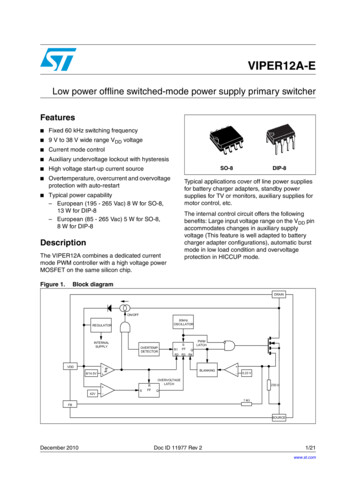
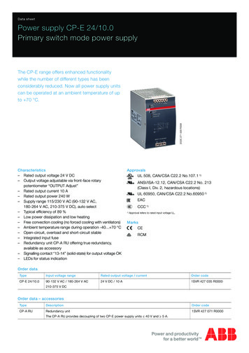
Technical diagramsOutput behaviourUout [V]28242CDC272007F0b082016124246810121614Iout [A]2CDC 272 007 F0b088Characteristic curve of output at Ta 25 CThe switch mode power supply CP‑E 24/10.0 is able to supply at 24 V DC output voltage and––at an ambient temperature of: 60 C a continuous output current of approx. 10 A––at ambient temperatures of:60 C Ta 70 C the output power has to be reduced by 2.5 % per C temperature increase.If the switch mode power supply is loaded with an output current 10 A, the operating point is passing through theU/I characteristic curve shown.Temperature behaviourPout [%]2CDC272017F0211100908070605040302010-406070Ta [ C]Characteristic curve of temperature at rated loadDimensionsin mm [inches]83,0 [3.27“]123,6 [4.87“]2CDC272003F0b082CDC 272 003 F0b08123,6 [4.87“]116,6 [4.59“]CP-E 24/10.0Data sheet Power supply CP-E 24/10.0 - 9
Dimensions accessoriesin mm [inches]93,5 [3.68”]203,5 [8.01”]56,5 [2.22”]90,0 [3.54”]200,0 [7.87”] 2CDC 272 015 F0b07130,0 [5.12”] 130,0 [5.12”]130,0 [5.12”] 60,0 [2.36”]2CDC272015F0b07144,5 [5.69”]137,0 [5.39”]135,5 [5.33”]CP-A RUFurther documentationDocument titleDocument typeDocument numberElectronic Products and RelaysTechnical catalogue2CDC 110 004 C02xxPower Supply UnitsApplication manual2CDC 114 048 M020xRedundancy unit CP‑A RUData sheet2CDC 114 036 D0202You can find the documentation on the internet at www.abb.com/lowvoltage- Automation, control and protection - Power supplies.CAD system filesYou can find the CAD files for CAD systems at http://abb-control-products.partcommunity.com- Low Voltage Products & Systems - Control Products - Power Supplies.10 - Power supply CP-E 24/10.0 Data sheet
Contact usDocument number 2CDC 114 061 D0201 (08/2016)ABB STOTZ-KONTAKT GmbHP. O. Box 10 16 8069006 Heidelberg, GermanyPhone: 49 (0) 6221 7 01-0Fax: 49 (0) 6221 7 01-13 25E-mail: info.desto@de.abb.comYou can find the address of yourlocal sales organisation on theABB home pagehttp://www.abb.com/contacts- Low Voltage Products and SystemsNote:We reserve the right to make technical changesor modify the contents of this document withoutprior notice. With regard to purchase orders, theagreed particulars shall prevail. ABB AG doesnot accept any responsibility whatsoever forpotential errors or possible lack of information inthis document.We reserve all rights in this document and inthe subject matter and illustrations containedtherein. Any reproduction, disclosure to thirdparties or utilization of its contents – in wholeor in parts – is forbidden without prior writtenconsent of ABB AG.Copyright 2016 ABBAll rights reserved
Data sheet Power supply CP-E 24/10.0 - 3 Installation Mounting The switch mode power supply can be snapped on a DIN rail according to IEC/EN 60715 as shown in the accompanying picture. For that the device is set with its mounting rail slide on the upper edge of the mounting rail a