Transcription
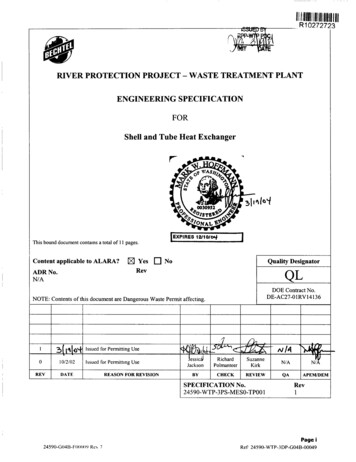
11111111111111111111111IIllR10272723RIVER PROTECTION PROJECT - WASTE TREATMENT PLANTENGINEERING SPECIFICATIONFORShell and Tube Heat Exchanger1]EXPIRES r u i o i This bound document contains a total of 1 1 pages.Content applicable to ALARA?ADR No.YesRevIbQuality DesignatorNoQLNIADOE Contract No.DE-AC27-01RV14136NOTE: Contents of this document are Dangerous Waste Permit affecting.REVIDATE1REASON FOR REVISIONIBYICHECKIREVIEWIQAIAPEWDEMSPECIFICATION No.Rev245 90-WTP-3PS-MESO-TP0011Page iRef. 24590-WTP-3DP-G04B-00049
24590-WTP-3PS-MESO-TPOO1, Rev 1Shell and Tube Heat ExchangersPlease note that source, special nuclear and byproduct materials, as defined in the Atomic Energy Act of1954 (AEA), are regulated at the U.S. Department of Energy (DOE) facilities exclusively by DOE actingpursuant to its AEA authority. DOE asserts, that pursuant to the AEA, it has sole and exclusiveresponsibility and authority to regulate source, special nuclear, and byproduct materials at DOE-ownednuclear facilities. Information contained herein on radionuclides is provided for process descriptionpurposes only.24590-GO4B-FOOO I9 Re\ 0Page 1Ref: 24590-WTP-3 DP-G04B-00049
24590-WP- 3PS- MESO-TPOO 1. Rev 1Shell and Tube Heat ExchangersContents.1Scope2Applicable 5.3.Codes .Industry Standards .Reference DocumentslDrawings.References .GeneralDesign Requirements3.13.Supplemental Quality Level Criteria for Heat Exchangers .Tubes and Tube Bundles .Tubesheets .Impingement Plates. Baffles and Seals .Channels .Shell. Shell Covers and Shell Supports.Flanged External Girth Joints .Expansion Joints .Basic Requirements.Quality Assurance .5.233344Supplemental Testing Requirements5.1344566778889.Quality (Q) Related Components.General Requirements99AppendicesAppendix ARevision History24590-GO4B-FO0019 Rev 0.A.iPage 2Ref 24590-WTP-3DP-G04B-00049
24590-WTP-3PS-MESO-TPOO1, Rev 1Shell and Tube Heat Exchangers1ScopeThis specification supplements the RPP-WTP Specification for Pressure Vessel Design andFabrication (2459O-WTP-3PS-MVOO-TPOO1). This specification, together with the purchase order,data sheets, and drawings, covers the requirements for the design, fabrication, and testing of shelland tube heat exchangers for the River Protection Project - Waste Treatment Plant (RPP-WTP)located at Hanford in the southeastern part of Washington State.2Applicable Documents2.12.22.3General2.1.1Work shall be done in accordance with the referenced codes, standards, anddocuments listed below, which are an integral part of this specification.2.1.2When specific chapters, sections, parts, or paragraphs are listed following a code,industry standard, or reference document, only those chapters, sections, parts, orparagraphs of the document are applicable and shall be applied. If a date orrevision is not listed, the latest issue, including addenda, at the time of Requestfor Quote (RFQ) shall apply. When more than one code, standard, or referenceddocument covers the same topic, the requirements for all must be met with themost stringent governing.Codes2.2.1American Society of Mechanical Engineers, Boiler and Pressure Vessel Code,Section VIII, Division I, Rules for Construction of Pressure Vessels(Applicab1e toQL1 and QL2 category components only)2.2.1American Society of Mechanical Engineers, Quality Assurance Requirements forNuclear Facilities, ASME NQA-1 (1989)Industry StandardsStandards of the Tubular Exchanger Manufacturers Association (TEMA Standard) Eighth Edition - 19992.4Reference DocumentdDrawings2.4.1RPP-WTP Specification for Pressure Vessel Design and Fabrication, 24590WTP-3PS-MV00-TP0012.4.2RPP-WTP Specification for Supplier Quality Assurance Program 001 9 Rev 0Page 3Ref: 24590-WTP-3DP-G04B-00049I
24590-WP-3PS-MESO-TPOO1, Rev 1Shell and Tube Heat Exchangers2.5ReferencesZick, L. P., “Stresses in Large Horizontal Cylindrical Pressure Vessels on Two SaddleSupports”, page 959, Pressure Vessels and Piping: Design and Analysis, A Decade ofProgress, Volume 11, published by ASME.3Design Requirements3.13.2Basic Requirements3.1.1Unless otherwise specified, all shell and tube heat exchangers shall be designedand fabricated in accordance with the ASME Section VIII Division 1, the TEMAstandard, the RPP-WTP Specification for Pressure Vessel Design and Fabrication,and any additional requirements of this specification and the referenced drawings.3.1.2The Buyer’s thermal design requirements will be shown on the individualMechanical Data Sheet (MDS). When the Buyer’s MDS or Mechanical Drawingshow the mechanical sizes (diameters, length, tube number, sizes, etc.), this datashall be considered as preliminary. Seller shall verify the thermal, hydraulic andmechanical designs. Where necessary, the Seller shall change the exchanger sizein order to furnish complete thermal, hydraulic and mechanical guarantees. Sellershall calculate the heat transfer rate for each unit and base the design on theminimum surface necessary to guarantee that the heat exchanger offered issatisfactory for the duty and fouling factors specified. Buyer’s preliminary areaestimate, where specified and determined to be conservative, shall prevail.3.1.3If ASME Section VIII, Division 1 specifies two allowable stresses for the designof pressure parts, the lower value must be used for the design of tubesheets,bolted flanges, and flat cover plates.3.1.4The steam condensing side of any heat exchanger shall be designed for fullvacuum. In addition, any chamber subjected to partial vacuum in any serviceshall be designed for full vacuum unless otherwise noted or approved by theBuyer.3.1.5When stacked exchangers are specified by Buyer, Seller shall be responsible forinvestigating and solving any thermal-expansion related problems for theinterconnecting nozzles and supports.3.1.6Floating head construction shall not be used unless otherwise noted on the MDSor approved by the Buyer. A “packed gland” type is not acceptable.Supplemental Quality Level Criteria for Heat Exchangers3.2.124590-G04B-F00019 Rev 0Heat exchanger quality level shall be specified on the MDS by the buyerPage 4Ref: 24590-WTP-3DP-G04B-00049
24590-WP-3PS-MESO-TPOO1, Rev 1Shell and Tube Heat Exchangers3.33.2.2Quality Level 1 heat exchangers shall be TEMA Class B and shall be of allwelded construction. Tubes shall be welded to the tubesheet(s) with full strengthwelds. The tubes shall include a corrosion allowance, shown on the mechanicaldrawing, for the process side of the tube walls.3.2.3Quality Level 2 heat exchangers shall be TEMA Class B and shall be of allwelded construction on the process fluid side. Tubes shall be welded to thetubesheet(s) with full strength welds.3.2.4Commercial Quality heat exchangers shall be TEMA Class C or B with norestriction on body flanges. For heat exchangers in cyclic services, tubes shall bewelded to the tubesheet(s) with strength welds.Tubes and Tube Bundles3.3.1Tubing shall be seamless unless otherwise noted or approved by Buyer. Tube-totube welddjoints are not permitted.3.3.2When tube outside diameter and thickness are shown on the mechanical drawing,they are for the straight tube section of the tube bundle.3.3.3Straight tube length shall be a maximum of 20 feet, unless otherwise noted orapproved by Buyer.3.3.4All austenitic stainless steel U-tubes shall be solution annealed after bending,unless otherwise noted or approved by Buyer.3.3.5If strength welded tube-to-tubesheet welds are not used, Seller shall verify that theyield strength of the tube material does not exceed the yield strength of thetubesheet material. This is to ensure quality rolling, expansion and sealing oftubes to tubesheet.3.3.6Tube bundles shall be designed, in accordance with the TEMA standard, toprevent tube damage that may be caused by flow induced or acoustic vibrations.3.3.7Weighted mean temperature difference (MTD) shall be used only when the Sellerprovides heat release curves or tables.3.3.8When calculating the effective surface area of the heat exchanger, the tube lengthwithin the thickness of the tubesheet shall be excluded.3.3.9For U-tube bundles with full diameter support adjacent to the bends, the surfacearea of the return bends shall not be included in the heat transfer calculations.3.3.10The number of tubes in any pass shall be within 10 percent of the average numberof tubes per pass.3.3.11For heat exchangers in non-radioactive service, with a tube bundle diameter 30inches or larger, skid bars shall be provided to facilitate bundle removal.Page 5Ref 24590-WTP-3DP-G04B-00049
24590-WP-3PS-MESO-TP001, Rev 1Shell and Tube Heat Exchangers3.3.123.43.5The maximum bundle diameter shall be 60 inches unless otherwise noted on theMDS or approved by the Buyer.Tubesheets3.4.1Tubesheet thickness calculations shall be in accordance with TEMA and be basedon both the corroded and uncorroded states.3.4.2When tube material is austenitic stainless steel, special close-fit tube holes perTEMA shall be used.3.4.3Unless otherwise specified by the Buyer, the design temperature for tubesheetsshall be taken as the larger of either the shell-side or tube-side designtemperatures specified on the MDS.3.4.4Four tapped holes for bundle pulling shall be equally spaced in the face of allremovable bundle tubesheets. Plugs of the same material as the tubesheet shall beprovided for plugging the holes.3.4.5When a bonnet-type head is used as the stationary end of a U-tube heatexchanger, the diameter of the fixed tubesheet shall be equal to the outsidediameter of the shell flange. The tubesheet shall be counterbored to accept collarstuds. Approximately 25%, with a minimum of four, of the flange studs shall becollar studs. They are to be provided with lock nuts on the shell-side of theflange. Tapped tubesheet bolt holes in lieu of collar studs are not allowed withoutprior Buyer approval.3.4.6When hub-type fixed tubesheets are required, the hub shall be integrally forgedwith the tubesheet. Hubs made from built-up weld metal shall not be permitted.3.4.7For multiple pass exchangers, the design of the exchanger shall take into accountthe effect of gasket seating at the pass partitions. Tube openings shall not beobscured by partition plates or gaskets.Impingement Plates, Baffles and Seals3.5.1Single pass tube-side design with axial nozzles shall use conical heads or shallhave a full diameter perforated plate in the inlet channel, which provides bothimpingement protection and even flow distribution.3.5.2For plate-type impingement devices, plates shall be circular solid plates that aresecurely fastened or welded to the spacer tubes or tie rods. The plate shall belocated a minimum distance of 0.25 times the nozzle inside diameter downstreamof the nozzle.3.5.3For rod-type impingement devices, the design shall include a minimum of tworows of rods on a triangular pitch. The rod diameter may be smaller than the tubediameter but there shall be an overlap of approximately 0.125 inch between rows.Page 624590-GO4B-FOOOI9 Rev 0R c f 24500-WTP-3DP-G04B-00049
24590-WP-3PS-MESO-TPOO1, Rev 1Shell and Tube Heat ExchangersThe top of the first row of rods must be located a minimum distance of 0.15 timesthe nozzle inside diameter downstream of the nozzle.3.5.4Shell-side baffles, support plates and partition plates shall be provided withminimum 3/8 inch notches to drain the heat exchanger.3.5.5For the transverse baffles in horizontal heat exchangers, horizontal baffle cutsshall be utilized for single phase and vaporizing shell-side services while verticalbaffle cuts shall be utilized for “high solids content” fluids and condensing shellside services.3.5.6Dummy tubes or solid bars shall be placed in the shell-side void areas caused bypass partition plates. These devices are not required for isothermal shell-sidevaporization or condensation, or when the baffle cut is parallel (or within 45” ofparallel) to the pass partition plate.3.5.7Bypass seal devices are required when the radial clearance between the outer tubelimit (OTL) and the shell is greater than one tube diameter. The bypass sealsshall be placed 1 to 3 inches fi-omthe baffle cut and approximately every six rowsof tubes, and shall extend to within the ligament distance of the tubes. Thesesealing devices are not required for isothermal shell-side vaporization orcondensation.Channels3.6.1For flat channel covers, the maximum allowable deflection shall be 0.03125 inch.3.6.2Flat covers welded to the channel are not permitted.Shell, Shell Covers and Shell Supports3.7.1Unless otherwise required by the design conditions, the minimum shell thickness,exclusive of corrosion allowance, shall be the greater of 1/4 inch or TEMAminimums.3.7.2The minimum permissible shell cover thickness specified in TEMA shall betreated as after forming, and shall not be less than % inch nominal.3.7.3Shell covers shall not be constructed of flat cover plates welded to the shell.3.7.4Shell supports shall be designed to withstand all supenmposed loads plus fifteenpercent margin. For stacked shells with shell diameter above 40 inches, fullwrapper plates shall be considered on the lower shell. Honzontal exchangersupports shall be designed per the L. P. Zick method or approved equal.3.7.5Heat exchanger shell shall be checked to ensure bundle installation withoutbinding (grinding of baffles to permit insertionheinsertion is not acceptable). Forhorizontal heat exchangers, bundles shall be withdrawn, after insertion, a distanceequal to the lesser of two central baffle spaces or 4 feet, then reinserted.Page 724590-GO4B-FOOO I9 Rev 0R e f 24590-WTP-3DP-C04B-00049
24590-WTP-3PS-MESO-TPOO1, Rev 1Shell and Tube Heat Exchangers3.83.9Flanged External Girth Joints3.8.1Unless otherwise noted or approved by the Buyer, body flanges shall be weldingneck.3.8.2All end flanges shall be checked for axial alignment and gasket face flatness afterwelding to the shell and stress relieving. Final gasket surface machining shall bedone after welding and stress relieving.3.8.3For flange bolting where the bolt diameters are 1-1/4 inch or greater, bolt lengthshall be increased in length by one bolt diameter to permit use of bolt tensioners.Flange dimensions must allow the use of the tensioner.3.8.4All gasket inside diameters shall be greater than the corroded inside diameter ofthe component it will seal.Expansion JointsIt is the Seller’s responsibility to determine the need for shell expansion for theconditions specified by the Buyer using TEMA rules. When determining the needfor an expansion joint in fixed tubesheet heat exchangers, the most stringent ofthe following shall be considered:3.9.10000000Normal operating conditions.Shell-side start-up; no fluid tube-side.Tube-side start-up; no fluid shell-side, shell at most severe ambient temperature.Loss of cold fluid on either shell side or tube side.Specified turndown operating conditions.HydrotestSteamout or other cleaning procedures, when specified.All conditions and the frequency (based on data supplied by the Buyer) shall beconsidered by the Seller. The Seller shall recommend the necessity of an expansionjoint to achieve the required equipment service life as stated on the MDS.43.9.2If an expansion joint is required, shell expansion joint shall be the flanged andflued type.3.9.3Flanged and flued expansion joint shall be the same material, with at least thesame thickness, as the shell (including corrosion allowance). Minimum thicknessshall satisfy both TEMA and ASME Section VIII, Division 1 requirements.Supplemental Testing RequirementsLeak Testing - Where tube to tubesheet welding has been performed, the welds shall be subjectedto a 15 psig air and soap bubble test before the hydrostatic test.24590-GO4B-FOOO I9 Rev 0Page 8Ref: 24590-WTP-3DP-G04B-00049
24590-WTP-3PS-MESO-TP001, Rev 1Shell and Tube Heat Exchangers5 Quality Assurance5.15.2General Requirements5.1.1The Seller’s Quality Assurance Program (QAP) Requirements are included in24590-WTP-3PS-GOOO-TOOO1, Supplier Quality Assurance Program.5.1.2Seller’s QAP Manual shall be submitted to buyer for review in accordance with24590-WTP-3PS-GOOO-TOOO1, Supplier Quality Assurance Program.5.1.3Seller’s QAP, as a minimum, shall contain the requirements detailed in theSupplier Quality Assurance Program Requirements Data Sheets listed in Section2 of the MR.Quality (Q) Related Components5.2.1Seller shall have in place a QA program meeting the requirements of ASMENQA-1-1989, marked as applicable in Supplier Quality Assurance ProgramRequirements Data Sheet attached to the MR, and Buyer specification 24590WTP-3PS-GOOO-TOOOl.5.2.2Deleted5.2.3All items shall be manufactured in accordance with the Seller’s QualityAssurance Program that meets the requirements of ASME NQA-1-1989, and hasbeen previously evaluated and accepted by the RPP-WTP Quality Organization.5.2.4Seller shall submit their QA program and work plan to Buyer for review prior tocommencement of work. The plan shall include documents and procedures toimplement the work and include a matrix of essential Quality Assurance elements7cross referenced with the documentslprocedures.Page 924590-GO4B-FOOO I9 Rev 0Ref: 24590-WTP-3DP-G04B-00049
24590-WP-3PS-MESO-TPOO1, Rev 1Shell and Tube Heat ExchangersAppendix ARevision HistoryRev. 0 -Issue specification for procurement, advance revision level from Revision B to Revision 0.Changes made in specification wording are highlighted with Revision bars.IRev. 1 -Issued for Permitting Use.RefPage A-i24590-WTP-3DP-G04B-00049
2.4.1 RPP-WTP Specification for Pressure Vessel Design and Fabrication, 24590- WTP-3PS-MV00-TP00 1 2.4.2 RPP-WTP Specification for Supplier Quality Assurance Program Requirements, 24590-WTP-3PS-GOOO-TOOO 1 24590-CO4B-FO001 9 Rev 0 Page 3 Ref: 24590-WTP-3DP-G04B-00049


