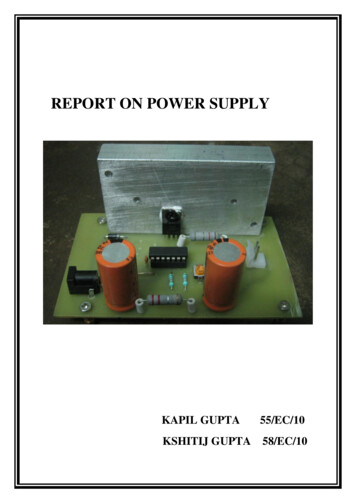
Transcription
SWITCH MODE POWER SUPPLY FAC P series.User, installation and start up manual.EK328J01
SAFETY WARNINGS. . 8-2-
We would like to thank you in advance for the trust you have placed in us by purchasing this equipment. Readthese instructions carefully before starting up the equipment and keep them for any possible future use.We remain at you entire disposal for any further information or any query you should wish to make.Yours sincerely.SALICRU According to our policy of constant evolution, we reserve the right to modify the specifications in part or in whole withoutforewarning All reproduction or third party concession of this manual is prohibited without the previous written authorization of our firm.-3-
General contents.1.- FAC DRAWINGS (see figures 8 to 14).2.- LEGENDS OF THE FAC DRAWINGS.3.-SAFETY WARNINGS.4.- DESCRIPTION AND BLOCK DIAGRAM.5.- PRESENTATIONS, VERSIONS AND NOMENCLATURE.5.1.- Presentations.5.2.- Versions.5.3.- Nomenclature.5.3.1.- Module.5.3.2.- System.5.3.3.- Structure system diagram with «n» modules in parallel with protections.6.- EQUIPMENT RECEPTION.6.1.- Reception and unpacking.6.2.- Storage.7.- INSTALLATION.7.1.-Look after your own safety.7.2.- To keep in mind .7.3.- Connection to AC mains, terminals (X1), (X2), (X3) and (X4).7.4.- Connection with the batteries (Only models with extended autonomies), terminals (X11), (X12) and (X47), (X48).7.4.1.- Version (B). Batteries of the client’s property, installed externally to the (Sfac).7.4.2.- Version (B *** ), supplied with batteries built in a separate cabinet or rack from the (Sfac).7.4.3.- Version (B 0 /*** ). Batteries of the client’s property, with foreseen space.7.5.- Connection of the DC supply to the loads, terminals (X6), (X9) or (X6A. X6*) and (X9A. X9*).and protective earth bonding terminal (X10) .7.6.- Main protective earthing terminal (X5)7.7.- Relay interface.7.7.1.- Relay interface in DB9 connector or terminals strip (X32), see figures 2.1 or 2.2.7.7.2.- Relay interface in terminals strip (X32), see figure 2.3 (only equipments with MS-101 optional).7.7.3.- Relay interface in terminals strip (X32), see figure 2.4 (only equipments with MS-102 optional).7.8.- Serial interface RS-232 or 485, DB9 connector (X31).7.9.- Temperature probe/battery floating voltage. DB9 connector (X34) or terminals strip (X25*).7.10.- Room ambient temperature probe. Terminals strip (X25*), (equipments with MS-101 only).7.11.- Terminals strip, auxiliary contacts of the (Sfac) protections.7.12.- Terminals strip (X43), auxiliary contacts of the battery cabinet protections.8.- START UP AND SHUTDOWN OF THE FAC.8.1.- Start up of the (Mfac) or (Sfac) (First start up or after a complete shutdown).8.1.1.- Module (Mfac).8.1.2.- System (Sfac).8.2.- FAC shutdown (daily operation, if the installation requires it).8.2.1.- Module (Mfac).8.2.2.- System (Sfac).8.3.- Complete FAC shutdown.8.3.1.- Module (Mfac).8.3.2.- System (Sfac).-4-
9.- FAC SYNOPTIC.9.1.- Optical indications.10.- REPLACING A FAC MODULE IN A SYSTEM (Sfac).11.- COMMON TECHNICAL FEATURES STANDARD MODULES.12.- PARTICULAR TECHNICAL FEATURES OF THE STANDARD MODULES.13.- SYNOPTIC VIEWS, FAC (Mfac) MODULES AND SYSTEMS (Sfac) VIEWS.-5-
1.- FAC DRAWINGS (see figures 8 to 14).2.- LEGENDS OF THE FAC DRAWINGS.Connection elements:(X1, X4)AC single phase input terminals (R-N) (X1), (X4).(X1, X2, X3, X4)AC three phase input terminals (R-S-T or R-S-T-N) (X1), (X2), (X3) or (X1), (X2), (X3) and (X4).(X5)Main protective earthing terminal, identified with the label .Some equipments has only one point of earth connection - copper bar - (X5) which is used to connect theearth coming from the input and the one coming from the load/s and battery cabinet/s.(X6, X9)DC output terminals ( ,–) (for equipments with outgoing distribution only).(X6A. 6*, X9A. 9*) DC output distribution terminals ( ,–) (the standard has the own terminals of the protections as terminalsand only under request the terminal strip with «n» terminals will be available).(X10)Protective earth bonding terminal for load/s and battery cabinet or rack, identified with the label .(X11, X12)Battery terminals ( ,–) (for equipments with batteries in whole or in part installed externally from the FAC cabinet).(X13)Protective earth bonding terminal for battery cabinet or rack, identified with the label(X25*)Terminals for room ambient temperature probe. Equipments with MS-101 only, and terminals fortemperature probe/battery floating voltage. Equipments with MS-101 or MS-102 only.(X31)DB9 connector, communication channel RS-232 or 485.(X32)DB9 connector or terminal strip, relay interface.(X34)DB9 connector, for temperature probe/battery floating voltage.(X35)DB25 or RJ-48 connector. Exclusive use for Service and Technical Support (S.T.S.) (only in FAC with led synoptic).(X40)Auxiliary contact terminals, general input protection «GENERAL INPUT».(X41A. X41*)Auxiliary contact terminals, individual input protections per each FAC module «INPUT MODULE».(X42)Auxiliary contact terminals, battery protection of the FAC cabinet «BATTERIES».(X43)Auxiliary contact terminals, battery protection of the battery cabinet or rack «BATTERIES».(X44A. X44*)Auxiliary contact terminals, individual output protections per each FAC module «OUTPUT MODULE».(X45)Auxiliary contact terminals, general output protection «GENERAL OUTPUT».(X46)Auxiliary contact terminals, general output protection of the outgoing distribution «GENERAL DISTRIBUTION».(X46A. X46*)Auxiliary contact terminals, output distribution protection «OUTPUT DISTRIBUTION».(X47, X48)Battery terminals ( ,–) of the battery cabinet or rack.Protection and manoeuvres elements:(F1)Tubular fuse, AC input protection of the module (FAC with 2U height only).(Q1)General input protection «GENERAL INPUT».(Q1A. Q1*)Individual input protections of each FAC module «INPUT MODULE».(F2)General output protection «GENERAL OUTPUT».(F2A. F2*)Individual output protections of each FAC module «OUTPUT MODULE».(F3)Battery protection of the FAC cabinet «BATTERIES*».(F6)General output protection of the outgoing distribution «GENERAL DISTRIBUTION».(F6A. F6*)Output distribution protection «OUTPUT DISTRIBUTION».(F8)Battery protection of the battery cabinet «BATTERIES*».Usually all the protections used in the equipment are switches with fuses (F*), except for the input switches are circuitbreaker protections (Q*). Under customer’s request, it can be changed by other type, so then the description done inthis manual can have deviations in respect to the equipment. Operate responsibly and in consequence, attending to theprotection type of your equipment.-6-
Control panel, optical indications depending on the model:(a)Led «ON».(b)Led «Alarm».(c)Led «Floating voltage».(d)Led «Discharge».Control panel, LCD and keypad (equipments with LCD panel only. Not available in FAC 2700 module):(e)Display.(f)Key «ON» in led synoptic or «ENT/ON» in LCD synoptic.(g)Key «OFF» in led synoptic or «ESC/OFF» in LCD synoptic.(h)Move forward key« ».(i)Move back key « ».(j)Move to right key « ».(k)Move to left key « ».Abbreviations and different elements:(AS) / CAModule handle or marksman and (MS-102). / Lifting ring to elevate the equipment.(BAT.)Battery cabinet.(CL)Cabinet lock with or without key locking, either standard or special.(FAC)Spanish acronym for «Switch Mode Power Supply ». It is used generically to refer the product.(Mfac)FAC module, rectifier unit.(MS-101)Analyser monitor with 20x2 characters (See user’s manual EK314*02)(MS-102)Analyser monitor with 40x4 characters(See user’s manual EK399*02).(PA)Front door of the cabinet.(PB)Fixing elements.(PR)Cable glands.(RC)Slot to enter the cables.(RV)Cooling grid.(Sfac)FAC cabinet system.(TB)Terminal cover.Analyser fixing screw (MS-101) or (MS-102).(TF1)Module fixing screw and cover terminals (TB) and top socket (TZ).(TF2)Top socket (two per cabinet, delivered inside the same).(TZ)SIMBOLOGY USED IN THIS MANUAL AND/OR ON THE EQUIPMENT.«Warning» symbol. Carefully read the indicated paragraph and take the stated prevention measures.«Danger of electrical discharge» symbol. Pay special attention to it, both in the indication on the equipment and inthe paragraph referred to this user’s manual.«Main protective earthing terminal» symbol. Connect the earth cable coming from the installation to this terminal.«Protective earth bonding terminal» symbol. Connect the earth cable from the loads or battery cabinet to this terminal.«Notes of information» symbol.Preservation of the environment.The presence of this symbol in the product or in their associated documentation states that, when their useful life isexpired, it will not be disposed together with the domestic residuals.To avoid possible damages to the environment, separate this product from other residuals and recycle it suitably.The users can contact with their provider or with the pertinent local authorities to be informed on how and wherethey can take the product to be recycled and/or disposed correctly.-7-
3.-SAFETY WARNINGS. Together with the equipment and this «User’s manual», it is supplied information referred to «Safety instructions» (See documentEK266*08). Before proceeding with the installation or start up, make sure that you have both sets of information, otherwiserequest them. It is a must the compliance referred to the «Safety instructions», being the user the responsible of its observance.Once read, keep them for future consults that can arise.PARTICULAR SAFETY WARNINGS.The FAC product described in this User’s manual, has been designed, manufactured and commercialised in accordance withthe standard EN ISO 9001 of Quality Assurance. The CE marking states the conformity to the EEC directives in accordancewith the following standards: EN 60950-1: 2001. IT equipments. Safety. Part 1:General requirements. EN 61204-3:2000. Power supplies of low voltage, with D.C. output Part 3: Electromagnetic compatibility. ETS 300386-2. Electromagnetic compatibility requirements for telecommunication equipments. Part 2 Product familystandard.L.V. SAFETY: The FAC is an electrical equipment with protection of Class l. It is essential to connect the protective earth cable to the rightterminal in order to be protected against electrical shocks. The protective earth cable must be separated from the Telecommunication network, (to which the output of the DC power supply will be connected). The earth connection is guaranteed although the input protections trip. The equipment has an input protection against surges voltages of 5 kV (impulses of 8/20 µs). If higher surges areexpected, additional protection must be used. The insulation distances provide a pollution degree 2 (P2), in accordance with the standard HD 625.1. S1 (IEC 664-1mod.): nonconductive pollution, except for occasional condensation.Additional protections must be added for highly polluted environments (with conductive particles) or with frequent humiditycondensation. The equipment has a thermal protection device to protect the power semiconductors. This device breaks the operation of thesystem from a certain temperature; when cool the power supply restores the feeding. Make sure that this function is notdangerous when the voltage is restored suddenly. The safety level at the output of the FAC circuit is a Telecommunication Network Voltage Circuit. According to the referredstandard EN 41003, the output requires the same insulation features as Telecommunication Network to which it will be connected. Make sure that the rest of the installation connected to the output of the system must also comply thoserequirements.-8-
4.- DESCRIPTION AND BLOCK DIAGRAM.InputfilterPFC 1DC / DCConverterRectifierOutputFilterAC INPUTDC OUTPUTControlPFC 1InputPowerSupplyDC / tchMicro.ControlBatteriesFig. 1.1. Module block diagram of FAC P series.The operating principle of the FAC P series, is based in the conversion of the input alternating current, previously conditionedby a line filter, to direct current after being transformed, rectified and controlled.By means of fast transistors of high performance and starting from a 385 V DC, the DC / DC converter generates an alternatingcurrent at 40 kHz, which is after rectified with ultrafast diodes and conditioned through an efficient system of filtering.A special power transformer, isolates galvanically the input from the output, and reduces the alternating voltage to the requiredvalue to generate the wanted DC voltage.The output voltage and current are controlled by pulse width modulation in the transistors located in the primary winding ofthe transformer.A static switch is located at the output of the FAC, and it is in charge of disconnecting the batteries when they reach the enddischarge voltage, regardless if the batteries are supplied in the same FAC cabinet or not, in the case of power supplies withautonomy.The vital constants of the power supply are digitally controlled through a microprocessor, which is the responsible to manage thedisplayed adjustments and measures, in case it has a synoptic with LCD panel (not available for FAC 2700).All the FAC have the same operating, regardless the format, power and input-output voltages.Thanks to its parallelable feature and the capacity to store energy in a battery set and to have high autonomies, makes theFAC P series a product range highly suited for different high technology applications.-9-
5.- PRESENTATIONS, VERSIONS AND NOMENCLATURE.5.1.- Presentations.Each FAC unit (Module (Mfac)) is manufactured as a separate unit and assembled in 19’’ or metric sub-racks. They areprovided with power terminals and DB9 connectors for the communication channels, or with only one plug-in connector thatgroups all the connections, less the FAC 2700, which is only available in the plug-in version and it is also the only one withvertical format.Each FAC 2700 are not connected directly to the back-plain of the system (Cabinet (Sfac)) as it is done in the rest, but ratherthey are connected to the back-plain located in a 19’’ sub-rack with 6U height, which at the same time it is fixed mechanicallyto the system (Sfac). Each sub-rack allows to insert up to 6 rectifiers.Each system is able to have a certain quantity of rectifiers connected in parallel or redundant «N 1», depending on: thenumber of units of the cabinet (height), the rectifier model and the configuration set (included analyser, number and type ofprotections, outgoing distribution, auxiliary contacts of the protections, .).Technically the maximum quantity of rectifiers to be connected in parallel is 16 units for (MS-101) analyser and 64 for(MS-102). However, although it is technically possible, each particular case needs a viability study.In the figure 9 is only showed the rear view of the models with terminals, because the plug-in versions are reserved to makemodular structures of «n» parallel units and they don’t require any work for their electrical connection.Generally the rectifiers supplied as individual units or systems with only one rectifier, are manufactured with the synopticwith LCD panel, and the led version is reserved for parallel or redundant «N 1» systems with (MS-101) or (MS-102) analyser.Nevertheless it is possible any configuration due to the modularity of the rectifiers and to their independence because theyare intelligent, so it allows to manufacture tailor-made equipments for each client and/or application. If also batteries areadded, it will be a DC Uninterruptible Power Supply.The figures 10 to 14 show the layout of the elements that configure a power supply in a rack cabinet (System (Sfac)), they are onlymere guides, because there are multiple combinations, and the operating of the equipment does not depend on the layout. If anyof the referred parts are not in your equipment , omit all references to it, and on the other hand, if it includes elements that are notdescribed in this manual, additional annexes will be edited if necessary. Furthermore, the equipment is delivered duly labelled, sopay attention to it.Two poles fuse-switch are used for the protections of the outgoing distribution, considering the system with floating outputvoltage. And for other types of connection like positive or negative to ground, the fuse-switch protection will only have onepole. As outgoing distribution terminals will be the own ones of the two poles fuse-switch protections or single pole for the live poletogether with a copper bar for the negative or positive, which corresponds to the pole connected to the earth. It is possible tomanufacture the (Sfac) with any requirement, so the unit can differ more or less from the standard (Sfac), according to therequirements.By default the input entry cable of the (Sfac) is foreseen bottom of the cabinet and connecting all elements must be arranged nextto this area.As a result of individual customer specifications can be manufactured with the entry of cables across the top cabinet.- 10 -
5.2.- Versions. Basic, as a simple DC power supply. As a Uninterruptible Power Supply with three possible options: Version (B). Equipment with connection terminals, with external batteries owned by the client. They will be installed andconnected by the client, under his responsibility in a cabinet, case or rack. Version (B *** ). Equipment supplied with batteries. Autonomy (*** ) according to the purchase order. Version (B 0 /*** ). Equipment supplied without batteries, but with the accessories and space to locate them depending on the autonomy/batteries (type - nr - voltage ), requested on the purchase order. The installation and connection of thebatteries will be done by the client and under his own responsibility.5.3.- Nomenclature.5.3.1.- Module.FAC 1000P-HMELFKT3/230-48-18A «EE90528»Particular specifications of an special equipment «EE».Output current of the module at floating voltage.DC nominal output voltage (*).AC nominal input voltage.3 Relay interface with 3kV insulation, it replaces the standard one.T External battery measurement. No indication, internal measurement.K External end of autonomy contactor. No indication, internal end of autonomy.F Isolation failure. Only for equipments with floating output (no connection of the positive or negative poles to earth) and the modulewith LCD panel.Check that the loads connected to the FAC, don not have anyconnection between anyone of the output poles and the earth,before starting the installation procedure.L Led synoptic. No indication, LCD synoptic.E Plug-in connection type. No indication, through terminals.M Metric format with width 533 mm. No indication 19’’.Disposition: H (horizontal), V (vertical).P FAC series.Model of the module.FAC Spanish acronym of «Switch Power Supply».(*) Reference to earth of the DC output voltage in the modules (Mfac).All the (Mfac) are supplied from factory with floating output voltage (no connection of the positive or negative poles to earth),being the user able to modify it according to the specific application needs. To make it, just connect a cable bridge between one ofthe output poles and the earth, which at the same time is connected with the frame of the equipment: Cable bridge between the output positive pole and earth, for connection (–Un). Cable bridge between the output negative pole and earth, for connection ( Un).Never make this connection out of the terminals of the own equipment.- 11 -
5.3.2.- System.3FAC 1000P/230-48-54A 120’ «EE90528»Particular specifications special equipment «EE».Autonomy of the system at total output current of the system.Total output current at floating voltage (a system with N N, the current of the redundant units is not included).48 Floating DC nominal output voltage (no connection to earth) (**).(–48) Negative DC nominal output voltage (postive to earth).( 48) Positive DC nominal output voltage (negative to earth).AC nominal input voltage.P FAC series.Model of the module.FAC Spanish acronym of «Switch Power Supply».Maximum number of installed modules or to upgrade. Omitted if it is 1.(**) If the positive or negative poles are connected to the earth (reference), the sign of the live pole will be indicatedtogether with the voltage value, for example (–48) for positive to earth or ( 48) for negative to earth.When there is not any sign of polarity together with the value of the voltage, it is floating. Where necessary change the connection type original factory output, must necessarily change the type of protection orprotections output, as detailed below:- To output floating, protección two poles.- To output with positive to ground, protection single pole in the negative pole.- To output with negative to ground, protection single pole in the positive pole.- 12 -
5.3.3.- Structure system diagram with «n» modules in parallel with protections.Communication ports.Q1AF2AQ1BF2BQ1Output distribution.F2F6AF6F2*Q1*Output.Input.MS-101 or MS-102.F6BF6*Batteries.F3End ofautonomycontactor.All the references related with the circuit breaker protections are identified with «Q*» and the fuses protections with «F*»in the description of this manual. Furthermore, under request only the components of the system will be labelled followingthe correspondance between the «documentation and the equipment labelling».When due to specific requirements the foreseen circuit breakers protections in the system are replaced by fuses and particuarlyfor those equipments with corresponding labelling «documentation-equipment», the acronym «Q» is replaced by an «F» or the «F»by an «Q» maintaining the same numerical order.The block diagram of the figure is an example structure because the number of modules connected in parallel and protections can vary, but in general terms the disposition of them if they are, will follow this block diagram.Fig. 1.2. Structural example of a FAC system with protections.- 13 -
6.- EQUIPMENT RECEPTION.6.1.- Reception and unpacking. On receiving the equipment, make sure that it has not been damaged during transport, to know it, the equipment must beunpacked. Otherwise, make all suitable claims to your provider or, short of this to our firm. Also make sure all the data in thenameplate adhered in packing of the equipment, correspond to those specified on the purchase order. If they are notequal, make your claim as soon as possible, with the serial number of the equipment and the references in the deliveryinvoice. Having completed the reception, it is better to pack the FAC again until it is commissioned, in order to protect it againstmechanical impacts, dust, dirt, etc. The packing of the equipment has a wooden pallet, cardboard or wooden enclosure depending on the case, corners ofexpanded polystyrene or polyethylene foam, polyethylene wrap and band. All of them are recyclable materials; thereforeif any of them are to be thrown away, they must be disposed in accordance with the applicable laws. It is better to keep thepacking in case it has to be used in future.6.2.- Storage. The equipment must be stored in a dry, well-cooled place and protected from the rain, water projections or chemical agents. Itis better to keep the equipment and/or battery cabinets, as the case may be, in their original packing, as it has been specificallydesigned to assure the maximum protection during transport and storage. Some FAC have sealed lead-acid or Nickel-Cadmium batteries, depending on the particular specifications of the purchase order,and they can’t be stored for more than 6 months (see battery recharging period, stated in the packing of the equipment). Afterthis time, charge the batteries till the floating level. The level can be checked in the LCD panel of the synoptic, through the(MS-101) or (MS-102) analysers depending on the available one in your equipment. This means to connect the equipment tothe commercial mains and start it up, read the respective chapters. Then pack the FAC in its original packing again, writingdown the new date of battery recharge on the respective label.Do not store the equipments where the ambient temperature is over 40º C or below -20º C, because the electricalcharacteristic of the batteries might be affected.- 14 -
7.- INSTALLATION. Check the safety warnings (see document EK266*08). Check that the data in the nameplate are those ones required for the installation. A wrong connection or manoeuvre, can make damages to the FAC and/or to the connected loads. Read the instructions ofthis manual carefully and follow the stated steps in the same order. In the description of this manual there are references to the connection of terminals and switch manoeuvres or protections that some models only have. Omit the references of those elements that are not available in your equipment. Some (Sfac) are supplied in cabinets with the front side closed by a door (PA) that can be completely solid, glass or witha transparent window and equipped with a lock (CL) with standard or special key for the mechanism. To do any installation,commissioning or maintenance operating, that door must be opened through that mechanism.When the corresponding operations are finished, for those equipments with available mechanism, the door (PA) shouldbe closed and blocked by using the available it and keeping the key in a save place. In models without front door (PA) provides a cover (TB) for terminals. Remove the cover to proceed with the work ofconnection and place it once again finished them. In the cabinets with removable battery trays, there is danger of overturning the cabinet when pulling out the battery trays,so the operator in such case can suffer serious injuries. Therefore it is a must to adhere warning labels in visibleareas, advertising the need to fix the cabinet to the floor or the wall with elements that guarantee a total andpermanent solidity. All systems configured with (Mfac) 2700 VA vertical, is delivered with the modules packaged and placed on a trayof batteries inside the cabinet, secured by straps.Once located and locked the cabinet to the floor, cut the straps that hold the modules, remove the packaging and placingthem in the sub-rack starting from the upper left corner. Finally fix the chassis through the corresponding screw (TF2).7.1.-Look after your own safety. As this equipment is protected against electrical shocks of class I, it is essential to install the protective earth cable to theterminal or copper (X5) identified with the label . All the connections of the equipment, including the control ones (communication ports, auxiliary contacts, .), should bemade with the switches and the protections in rest mode and the mains disconnected (mains switch of the FAC turned«Off»). Never forget that a FAC with batteries is a generator of electric energy, so the user must take all the cautions against directand indirect contacts. Generally the batteries are installed in the same cabinet as the (Mfac), so the terminal strip for the batteries will not beavailable in that cabinet. These terminals will only be available in those equipments with external batteries in one or morecabinets or racks in order to enable the connection of the system with the batteries. Take cautions with the batteryterminals, as there is hazardous voltage between the battery terminals and the earth, and it will be higher as higher is thebattery voltage. The manipulation and battery connection must be made or supervised by staff with battery knowledge.In equipments with autonomy 0’ or 0’/*, the acquisition, installation and battery connection will be always done by the enduser and under his own responsibility. The data referred to the quantity of batteries, capacity and voltage are stated inthe battery label adhered beside the nameplate of the equipment, respect strictly those data, the polarity connection ofthe batteries and the connection diagram supplied with this documentation.- 15 -
Due to the percentage of the weight of the batteries in front of the system one, they are supplied packed separately fromthe metallic cabinet or rack that will house them, so there is a posterior labour of placing and connecting them with thesupplied accessories.When the cabinet is placed in the foreseen location, and all the covers have been removed and it is fixed to the floor or tothe wall, proceed to place the batteries with the same disposition as states the supplied annex documentationreferred to the disposition and connection of the batteries. Start from the lower tray in order to seat it and go to thenext level as soon as the tray is completed.Make sure that once the battery tray is completed, it is pushed into the cabinet again, this way we will avoid mechanicalefforts over the chassis, which can twist the structure.Once the placement works are finished, connect them according to the same annex documentation and taking care ofboth not extracting more than one tray and respecting the safety instructions of the battery part stated in the manualEK266*08.7.2.- To keep in mind . The cross section of the input and output cables shall be sized from the nominal currents stated in the nameplate, andrespecting the Local and/or National Electro-technical regulation of Low Voltage. The cable glands (PR) build in the metallic structure, are the stated ones to fix correctly the connection cables with theright cross section size determined by the National Electro-technical Regulation of Low Voltage and in accordance with thecurrents of the equipment. If the cross section needs to be modified, this should be done from a separate distribution panel,maintaining the stated cross sections from the equipment to the distribution panel.Some FAC have slots (RC) to make easy the entry and outlet of the connection cables.Modules with terminals and DB9 connectors (Mfac). The fitter must install circuit br
Power Supply DC / DC Control Output Power Supply Static switch Monitor Program. Micro. Control AC INPUT DC OUTPUT The operating principle of the FAC P series, is based in the conversion of the input alternating current, previously conditioned by a line filter, to direct c