Transcription
Electronic Engine ManagementAndCalibrationUser Manual1INTRODUCTION72ECU BASICS72.1ECU, SensingCrank and Cam SensorsManifold Absolute Pressure (MAP)Throttle Position Sensor (TPS)Coolant and Air temperatureOxygen (Lambda) sensor7788892.2ECU, Electronic Control2.2.1Fuel Injection2.2.2Spark Generation1010103113.1USING THE ECUUsual Wiring Information and Commonalities123.2Engine Calibration3.2.1Getting started with a new engineEngine Details3.2.2Injection Table3.2.3Ignition Table3.2.4Starting and Coolant Temperature Compensation3.2.5Dynamometer testing3.2.5.1 Compensations14141415191920224234.1GUIFileOpen ConfigurationSave ConfigurationDownload Configuration from ECUUpload Configuration to ECUComm Port Settings2424242424254.2Edit4.2.1General Engine Configuration26261
4.2.1.1 Mechanical SetupNumber of CylindersFiring OrderNumber of teeth on Crank sprocketNumber of missing teeth on Crank sprocketLast non-missing tooth on Crank sprocketNumber of teeth on Cam sprocketNumber of missing teeth on Cam sprocketLast non-missing tooth on Cam sprocketCrank tooth at Cam SensorSprocket correction angleMissing teeth ratioNumber of strokes for RPM averageCylinder correction angleLoad ParameterMissing Tooth AlgorithmCrank Triggering EdgeCrank Sensor ON VoltageCrank Sensor OFF VoltageCam Triggering EdgeCam Sensor ON VoltageCrank Sensor OFF Voltage4.2.1.2 Ignition SetupNumber of coilsCoil dwell timeNumber of sparksSparks off angleSpark delaySpark Output Pins4.2.1.3 Injection SetupNumber of Primary InjectorsPrimary Injector Output PinsPrimary Injector delayNumber of Secondary InjectorsSecondary Injector Output PinsSecondary Injector delayInjection angleInjection angle atNumber of Strokes for injectionMax Percentage Duty CyclePrimary injector flow rateSecondary injector flow rateTime for Fuel Pump On at bootFuel tank running timeAccumulated buttonFuel Pump Output Pin4.2.1.4 Limits and AlarmsCut Rev LimitTachometer Output Pin4.2.2Ignition 636372
4.2.3Injection Table4.2.4Sensor ConversionAddDeleteEditSensor NameUnitsFilterInput pinAmplificationThermocoupleInputSensor Conversion Table4.2.4.1 Throttle Position4.2.4.2 Manifold Absolute Pressure4.2.4.3 Coolant Temperature4.2.4.4 Air Temperature4.2.4.5 Lambda4.2.4.6 Wide Band Lambda4.2.4.7 Mass Air Flow4.2.4.8 Torque4.2.5Fuel Compensation4.2.5.1 Starting4.2.5.2 Throttle Pump4.2.5.3 Coolant Temperature4.2.5.4 Air Temperature4.2.6Spark Compensation4.2.6.1 Air Temperature4.2.7Idle RPM ControlMotor Wait TimeMotor On TimeMaximum Step ConstantMaximum Steps Motor Can MoveMinimum Active RPMIdle RPM when ColdIdle RPM when HotCold TemperatureHot TemperatureAllowed ErrorStep ConstantSampling PeriodMinimum TPS4.2.8Logs Setup4.2.9Launch ControlStart Line RPMNumber of Undriven WheelsNumber of Teeth on Undriven WheelsDiameter of Undriven WheelsNumber of Driven WheelsNumber of Teeth on Driven 5252523
Diameter of Driven WheelsEngine to Wheel RatioAllowed Slip when DryAllowed Slip When WetSwitch Off SpeedSampling Interval4.2.10 Digital InputsFunction nameDebounce timeActivation timeInput pinInverted4.2.11 Gauge View SetupFunction nameGauge typeColumnRow4.2.12 Switch outputsFunction nameSwitch NameOn-ValueOff-ValueOutput pin4.2.13 Closed loop Lambda4.2.13.1 Target TableParameters SetupNumber of turns for averagingNumber of turns to discardLambda no correction regionPercentage clamping boundsCorrection stepPercentage Bounds for RPM inside cellPercentage Bounds for Load inside cellFuel Compensations SetupPercentage bounds for overall compensationPercentage bounds for ‘ABC’ compensation4.2.14 Tables in Dyno 55565656565757575757575858584.3ActionUpdate Date and TimeStore Parameters in FlashRestore Parameters from FlashKill Engine59596060604.4ViewView Closed Loop Lambda Table60604.5Diagnostics4.5.1SparkMorse Test6161614
Operational Test4.5.2FuelMorse TestFlow Test4.5.3Enter Dyno Mode4.5.4Exit Dyno Mode4.5.5Crank/Cam oscilloscope view4.65LogsReset LogsDisable LogsEnable LogsDownload LogsAPPENDIX616161616262626464646465655.1Maximum value of DOI for engine655.2Idle Speed Control without Idle Speed Control Motor675.3Air Temperature Compensation on Fuel685.4General Engine Settings, Overview725.4.1Static setting725.4.1.1 Case 1 No missing teeth on crank and one cam tooth725.4.1.2 Case 2 Missing teeth on crank and no cam sprocket75Condition A when crank sensor points at a sector with no missing teeth75Condition B when crank sensor points inside the sector containing themissing teeth775.4.1.3 Case 3 No crank sprocket and with missing teeth on camsprocket 79Condition A when cam sensor points at a sector with no missing teeth79Condition B when cam sensor points inside the sector containing themissing teeth825.4.1.4 Case 4 No crank sprocket and with distributor835.4.2Dynamic setting84Case 1 Engines with no missing teeth on crank sprocket and one camtooth85Case 2 Engines with missing teeth on crank sprocket and no camsprocket85Case 3 Engines with no crank sprocket and with missing teeth on camsprocket85Case 4 Engines with no crank sprocket and number of teeth on camequal to “Number of Cylinders” with distributor865.5Fuel injection setup865.6Harness Wiring865
6GLOSSARY896
Reata Engineering, Electronic Engine Management and Calibration Manual1 IntroductionThis manual is intended to provide a brief overview on engine tuning, adetailed description of the Reata Engineering Graphical User Interface (GUI),and ECU wiring information. Readers that are new to engine tuning shouldfind the first chapters informative and are advised to read through them.Experienced tuners can go to the GUI and wiring chapters immediately.2 ECU basicsThe Engine Control Unit is used to control the operation of internalcombustion engines. Typically this involves the control of fuel quantity andspark timing as well as other ancillary controls. The ECU is a microprocessorbased electronic circuit that is capable of executing its code at very highspeeds and thus able to monitor and control the engine to crank angleresolution.The ECU operates off look-up tables to determine the appropriate value offuel quantity and spark timing.The look-up tables would usually bedetermined through experiment on the same engine.2.1 ECU, SensingThe ECU requires knowledge on the engine status in regards to its crankangle, engine rpm, engine load (determined through Manifold AbsolutePressure or Throttle Position Sensor), coolant temperature, air temperature,Exhaust Oxygen (Lambda) sensor etc. The sensors used are not unique andvary due to make and year of production. However some general descriptionon the sensors can be drawn.Crank and Cam SensorsThe function of the crank and cam sensors is to provide knowledge of angularposition and speed of the engine to the ECU. The ECU requires knowledgeof angular position of the engine crank so that spark and fuel are generated atMario Farrugia7
Reata Engineering, Electronic Engine Management and Calibration Manualthe desired crank angle. (details of the different crank and cam sensorconfigurations can be found in Appendix 5.4 ‘General Engine Settings,Overview’ )Usually these sensors are inductive type, two wire (or three wire) and operateon the principle that a voltage is generated in a coil when iron (a tooth) goespast the sensor at some speed. Other types of position sensing is sometimesused such as optical triggering or hall effect (hall effect requires use ofmagnets).Manifold Absolute Pressure (MAP)The MAP sensor is used to provide intake manifold pressure measurementwhich can be used as an engine load indicator.Sometimes this is alsoreferred to as Manifold Air Pressure, however the use of the word Absolute ismore descriptive as it has to be appreciated that the pressure being measuredis not gauge but absolute.Note that gauge pressure refers to pressurequantity above atmospheric pressure. Ambient pressure is 100kPa (14.7 psi)in an absolute scale and not zero.MAP sensors are typically three wire(ground, signal and supply) and vary in their pressure measuring rangedepending on application. Naturally aspirated engines typically utilise 100kPasensors while turbocharged (or supercharged) engines utilize 200kPa or300kPa sensors.Throttle Position Sensor (TPS)Usually a potentiometer directly connected to throttle body’s butterfly shaft.The overall electrical resistance of the potentiometer can vary from onesensor to another. However the overall resistance has practically no effect onthe throttle position measurement. The ECU reads the voltage at the wiperwhich is a function of the orientation (angular position) of the shaft.Coolant and Air temperatureThe coolant and air temperature sensors are usually thermistors. Thermistorsare resistors whose resistance changes with temperature.Mario FarrugiaUsed in8
Reata Engineering, Electronic Engine Management and Calibration Manualconjunction with a pull-up resistor, the thermistors and pull-up resistor make apotential divider whose voltage output depends on temperature. The voltageis read by the ECU to provide temperature measurement. The thermistor hastwo electrical terminals and therefore two connections to the harness,however sometimes the coolant temperature sensor has one side of thethermistor grounded to the engine and hence the sensor will have only oneelectrical terminal.Oxygen (Lambda) sensorThis sensor has seen a lot of evolution over the years. The fundamentalprinciple is based on the production of a voltage by zirconium dioxide elementwhen exposed to fresh air and exhaust gas. The most basic sensor is theone-wire sensor. The single wire provides a voltage that changes in relationto exhaust oxygen. The output signal of the single wire sensor referenced tochassis ground. The two-wire sensor provides two electrical connections onefor ground and the other for signal. Therefore the two-wire has better signalquality compared to the one-wire (note that the single wire’s groundconnection to the chassis is through the possibly rusted exhaust system ).Oxygen sensors require an operational temperature above 300 C to functionproperly. The three-wire senor has an embedded heater that heats up thesensor quickly on start-up thus enabling a much faster knowledge of exhaustoxygen. In a three-wire sensor, usually two wires are for the heater (typicallytwo white wires) and the third is signal (referenced to chassis ground). A fourwire sensor has two wires for heater (typically two white wires) and the othertwo wires are signal and signal ground. One, two, three and four wire sensorsprovide a voltage ranging from zero to 1Volt. A voltage of approximately 0.45volts indicates stoichiometric condition, voltages lower than 0.45 imply leancombustion while voltages higher than 0.45 imply rich combustion.Themeasured voltage cannot provide knowledge on the Air to Fuel Ratio AFR butonly knowledge whether rich or lean. Five-wire sensors do provide a voltagethat provides knowledge on the AFR. Five-wire sensors are also referred toas wide- band sensors. Wide band sensors have signal conditioning circuitryand provide a linearized voltage output with AFR.Mario Farrugia9
Reata Engineering, Electronic Engine Management and Calibration Manual2.2 ECU, Electronic ControlThe ECU controls the engine through fuel injection and spark timing. Forspark ignition engines, the quantity of fuel required is in direct proportion tothe quantity of air inhaled by the engine. The mass of Air to mass of Fuelratio (AFR) for ideal operation is stoichiometric. When a three way catalyticconverter is used in production vehicles, the AFR is cycled (through closedloop control) between rich and lean in order for the catalyst to be able toperform both oxidizing and reduction reactions.In racing applications theAFR is typically maintained rich (that is AFR smaller than AFR stoichiometric)because this produces more power and is safer for the engine.2.2.1Fuel InjectionSpark ignition engines operate at AFR close to stoichiometric. The quantity offuel required to obtain the required AFR is controlled by the amount of timethe injector is left open, and is referred to here as Duration Of Injection (DOI).The DOI required at any condition depends mostly on Volumetric Efficiencywhich in turn is very dependent on engine rpm. The DOI required is alsodependent on engine load which is determined through the MAP or TPSsensors. It is noted here that the logical consumption of much more fuel athigher rpm is due to the fact that the DOI applicable is injected everyrevolution (or every other revolution). Fuel injectors are very quick-acting onoff valves capable of being cycled (that is opened and closed) in the order of amillisecond. Injectors are available in a variety of flow rates and are alsodivided into low impedance and high impedance injectors depending on theirelectrical resistance. Peak-and–hold drivers can drive both low impedanceand high impedance injectors while saturation drivers can drive highimpedance injectors only.2.2.2Spark GenerationThe timing of the spark is critical for optimal engine operation. Typically sparktiming has to be advanced with increasing engine rpm. This is due to the factthat spark has to be generated in an earlier crank angle if the flame front is toMario Farrugia10
Reata Engineering, Electronic Engine Management and Calibration Manualtravel across the combustion chamber at higher rpm while still fullycombusting all gases just several degrees after top dead centre. The optimalspark timing is also dependent on engine load. Lighter engine loads requiremore advanced spark due to a slower moving flame in lower densitycombustion gases. In older mechanical systems this spark advance at lowengine loads was achieved by the vacuum advance system. Various types ofspark generation and delivery are available, namely, one coil with distributor,a coil every two cylinders (wasted spark) and an individual coil for eachcylinder. The spark, as with the older contact breaker setup (make and break)is generated by the switching-off of current to the coil. This is so because thecoil (inductor) cannot allow the magnetic flux to vanish immediately andtherefore a high voltage is produced which is capable of producing anelectrical discharge across the spark plug gap. The Capacitive DischargeIgnition (CDI) delivers a quantity of electricity to the coil at a very high voltageon the primary side of the coil (can be 300V).This high voltage in CDIsystems charges the coil a lot faster and leaves enough time to recharge andspark the plugs more than once per engine cycle (multi spark).3 Using the ECUThe ECU is an electronic circuit using state of the art microprocessor,memory, signal conditioning and power transistors.The wiring diagramshould be well followed before connecting power to the system. Damage tothe ECU can be done if wiring is not correct or not following the wiringsuggestions. This applies most of all to making sure that ECU pins that aresupposed to be connected to power are correctly connected to the relevantpower, while pins that are not supposed to be supplied with power aren’tconnected to power. It is also worthwhile mentioning that high voltage spikes(around 350V) are generated by the spark plug coils even on the low voltageside (that is ECU side). These high voltage spikes are properly handled bythe coil drivers but should not be connected to any other ECU pins other thanthe coil drivers.Before using the ECU, the wiring strategy must be developed. The attachedwiring diagram should be used as the basis of the strategy, with modificationsMario Farrugia11
Reata Engineering, Electronic Engine Management and Calibration Manualas necessary for the particular user application such as fuses, starting,charging and other ancillary circuits.3.1 Usual Wiring Information andCommonalitiesECU’s are powered from battery voltage, nominally 12V. The battery voltageis not actually 12V all the time as during cranking voltage will surely drop,while during charging voltage would be around 13.8V. The spark plug coils,injectors, oxygen sensor heater, relays, dashboard indicator lights and otherancillaries will typically run off 12V supply. The ECU internal electronics willtypically run at lower voltage. This voltage was 5V until recently and now is3.3V. Sensors will also typically be powered by a lower voltage, typically 5V,however some sensors do get powered by the battery 12V. Sensor signalsare typically between 0 and 5V, one exception is the two wire inductive pickup(used for crank and cam sensors) whose output voltage increases from lessthan a volt at low rpm but can reach as high as 20V depending on application.Due to the fact that ECU electronics and power electronics have a commonground but a different high side voltage as described above, switching of thepower circuits by the ECU electronics is achieved by closing or opening theconnection of the power circuits to ground. That is, coils and injectors wouldhave a continuous 12V supply (battery voltage), the ECU would then turn onthe coils and injections by supplying a ground connection to them. Turning-offof the power is achieved by breaking the connection to ground.Such astrategy was also used in the past on mechanical contact breakers systems.At this stage it is appropriate to note that due to the fact that all current fromcoils, injectors and other power circuits flows into the ECU through the lowvoltage side (ECU side) of these power consumers, the ground currentflowing out of the ECU is very high when compared to the much smallercurrent flowing into the ECU from the battery positive supply to power theECU electronics. This fact needs to be appreciated to recognize why thereare typically many more ground connections compared to the 12V positivesupply connections.It is advised that all these ground connections areconnected so that there is ample current handling capability.Mario Farrugia12
Reata Engineering, Electronic Engine Management and Calibration ManualAnother word on grounds, different types of grounds are cited, namely batteryground and analogue ground. Battery ground is the ground that is directlyconnected to battery, its main feature is its huge current carrying capacity, thecurrent flowing from coils and injectors would be routed to this ground insidethe ECU.The analogue ground is the ground that is used by analoguesensors, analogue meaning voltage that can vary continuously betweenground and supply voltage. Examples of analogue sensors are TPS, MAPand temperature sensors. The voltage output of these sensors varies in directproportion to the measured parameter. Therefore the ground voltage level ofthese sensors has to be very stable otherwise a slight shift in the voltage levelof the ground would be erroneously translated into a change in the measuredparameter value. It should be noted that battery ground would have discreteshifts in ground voltage level due to the turning on and off of coils andinjectors and turning on and off of other digital electronics. A filter to cancelthese shifts in ground level is typically employed to produce a clean analogueground. The supply voltage to the analogue sensors (typically 5V) would alsobe a clean voltage, that is it would also be without any voltage shifts due toswitching. Appreciating the differences between these ground and supplies isimportant so that connections are made to the appropriate terminals and notjust by whatever happens to seem the easiest physical connection on thevehicle.Heat dissipation: Electronic circuits do need to get cooled and cannot operateat high temperatures. The ECU heats up in part due to the microcontrollerand associated electronics but mostly due to the power transistors associatedwith switching on and off of the coils, injectors and other auxiliaries. Thereason behind the heat generated by power transistors is due to the fact thatwhen switched on, the power transistors would have a voltage drop acrossthem say of 0.8V. Therefore if a coil draws 5Amps in saturation, it wouldtranslate in 4W (P IV, P 5*0.8 4) of heat generated in the transistor that hasto be dissipated into the surroundings. Therefore ECU’s typically have therecase that functions as a heat sink for the internal electronics. To make surethe heat sinking is effective, the ECU should be mounted in a relatively coollocation and if possible have air current or mounted to heat sinking (and cold)metal parts.Mario Farrugia13
Reata Engineering, Electronic Engine Management and Calibration Manual3.2 Engine CalibrationIn this section on engine calibration a strategy is described to map an engineeven if no knowledge of injector DOI is known beforehand.Simplecalculations of injection duration are suggested to provide a baseline fueltable from which the engine could be started, and then fuel tables are finetuned by experiment. Similar baseline numbers for ignition timing are given.Experimental dynamometer testing would then usually be the next logical stepto determine spark/fuel hooks, MBT timing and whether to inject onto open orclosed intake valves.Since the fuel quantities for a new application might be significantly differentfrom other applications which the end user might have encountered, the lookup tables must be generated from a clean sheet.A simple process forgenerating fuel tables will be described herein.3.2.1Getting started with a new engineThis manual describes a process used to calibrate the settings for an enginewhich is new to the end user. It is assumed that at this point an engine andprogrammable ECU would have already been committed.The calibrationprocess here is described by giving reference and going through the processas used for calibrating a 600cc Honda motorcycle engine. A simple andsystematic process of establishing and building the spark and fuel tables andtesting of the engine is described. The first priority would be to establish thebaseline fuel table and ignition table with which to start and run the engine.Engine DetailsTo get started, some basic engine parameters must be known.For theHonda F4i engine used in this study, some of the fundamental engineparameters are summarized in Table 1 below:Mario FarrugiaEngine TypeF4iBore67.0 mmStroke42.5 mm14
Reata Engineering, Electronic Engine Management and Calibration ManualEngine Displacement599 ccCompression Ratio12:1Firing Order1-2-4-3Idle speed1300rpmTable 1 Honda CBR600 F4i Parameters [Honda User’s Manual]3.2.2Injection TableBefore starting the engine, some initial calculations need to be performed toestablish a preliminary fuel look-up table. The approach is to calculate howmuch fuel would be necessary for stoichiometric combustion in each cylinder,assuming that each cylinder is filled with air at atmospheric pressure (100%volumetric efficiency). The fuel quantity for idle conditions is then calculatedfor an expected typical MAP value at idle.For one cylinder of 150cc filled with air (only) at 100kPa and 20 C (293K),using the Ideal Gas Law we haveMass of air ma PV 100 10 3 Pa 150 10 6 m 3 JRT287 293Kkg K 1.78 10 4 kgNext, if the stoichiometric air-to-fuel ratio is 14.5, then the mass of fuelrequired per cylinder per cycle would be,ma1.78 10 4 kg AFR14.5 1.23 10 5 kgMass of fuel m f For gasoline of Specific Gravity of 0.75 [Heywood, Internal CombustionEngine Fundamentals]1.23 10 5 kgkg0.735l 5 1.64 10 l 0.0164mlVolume of fuel V f Mario Farrugia15
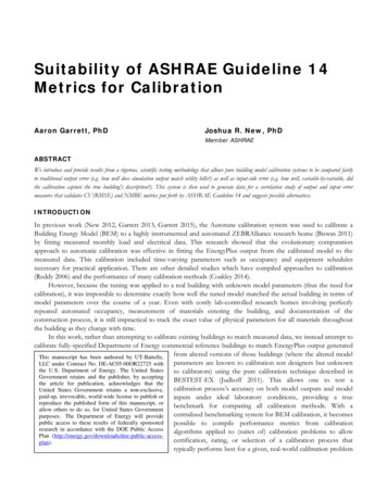
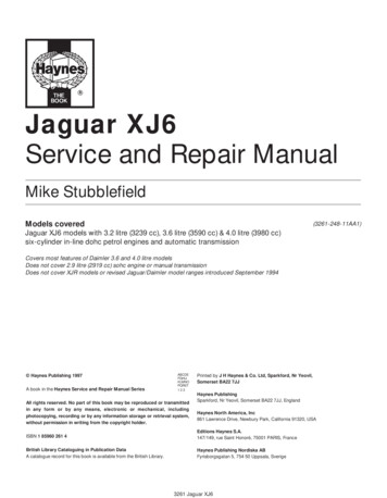
Reata Engineering, Electronic Engine Management and Calibration ManualFigure 1 Injector Flow TestAs an example the flow test from the Honda 600F4i stock injectors is detailed.The flow rate was measured by pulsing the injectors for 8ms, while countingthe number of injection events, and measuring the total volume of fuelcollected in a graduated cylinder. Table 2 shows the fuel injector calibrationmeasurements. A fuel flow bench feature is implemented in the Reata ECUspecifically for this kind of test (in GUI: Diagnostics, Fuel, Flow test). Theaverage volume for the injectors was 0.0280 ml per 8 ms pulse.Mario Farrugia16
Reata Engineering, Electronic Engine Management and Calibration ManualFuelInjector #Press[psi]VolumePulse[ml]CountFlow[ml /8ms]1 run 1507727190.02831 run 2507827490.02842 run 15078.528270.02782 run 2507827900.02803 run 1507928670.02753 run 2507928770.02754 run 1507727320.02824 run 2507827580.0283Table 2 Fuel Injector Experimental DataExperiments on other injectors showed that the fuel flow rate is approximatelylinear with injector open time, that is, the actual time that the injector needle isopen. It was determined that the time to open the Honda injectors was 0.2 to0.5ms. This is the time required to activate the solenoid and open the injector,before any fuel is released. The actual injection open time would be (8 – 0.5)ms, but the small difference was not important here as the purpose is to justestablish a baseline from which to begin dynamometer testing. Assumingthen a linear relationship, the pulse time required for stoichiometriccombustion can be calculated as:8x 0.0280 0.0164So, for this case, the injection duration, x, would be about 4.7 ms.Thiscalculation presumed a cylinder filled with air at 100kPa, which relates to wideopen throttle (WOT), 100% volumetric efficiency. At idle most engines wouldrun close to 40kPa, which considering the Ideal Gas Law would imply thatthere would be close to 40% of the mass of air at WOT. Therefore we wouldneed 40% of the 4.7ms, that is 1.9ms at idle.For the first engine trials being described here, we did not have an idea ofhow the volumetric efficiency changes with rpm. Therefore, our initial fuelMario Farrugia17
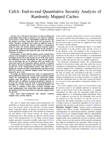
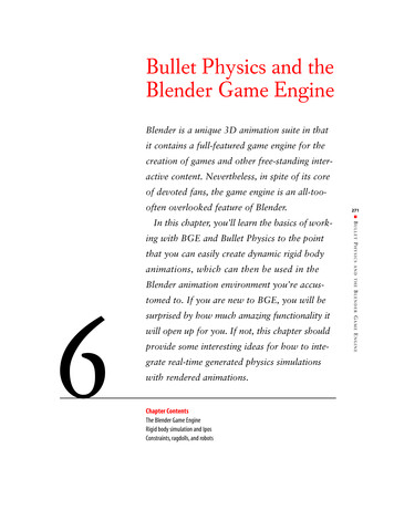
Reata Engineering, Electronic Engine Management and Calibration Manualtable was only a function of load. That is, our fuel injection duration was4.7ms at WOT for all speeds, and 1.9ms at zero throttle for all speeds. Theintermediate throttle positions were linearly interpolated between these endvalues. The initial fuel table is shown in Figure 1, which is in the form of awedge. It is not dependent on speed, simply 1.9ms at zero throttle and 4.7msat 504.002.50-3.003.502.00-2.50fuel (ms) 3.001.50-2.001.00-1.502.502001000080004000tps %2000100 8060 4001.0065001.50130002.00rpmFigure 2 Initial Fuel TableThe load parameter shown in Figure 2 is TPS, however the calculations werebased on a load condition described by MAP in kPa. This equivalence indescription of no-load as 40kPa in a MAP based table and 0% in a TPS basedtable is fine. The same applies to full load condition, where this is describedby 100kPa in a MAP based table (naturally aspirated) and 100% TPS in TPSbased table. However the linear relationship, described by the slope of Figure2 is only really applicable to a MAP based table. The MAP value produced ata specific TPS opening, it not constant with engine rpm and this would effectthe fuel requirement. Nonetheless Figure 2 is a valid initial table from wherethe engine can be started.Mario Farrugia18
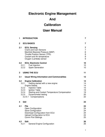
Reata Engineering, Electronic Engine Management and Calibration Manual3.2.3Ignition TableThe Honda Service Manual states that the spark advance is thirteen degreesbefore TDC at idle. Thirty degrees advance at high rpm is quite normal forengines; hence the initial table was set to have 13 advance at idle (1300rpm) and 30 advance at 6000 rpm. It is also quitecommon for racing engines not to have any load offset to timing i.e. novacuum advance.Hence the initial ignition table was setup to be only afunction of speed. Refer to Figure ion20.0 Advance15.0(Deg)10.05.0100806040tps %201300011000900080007000600040000 20000.0rpmFigure 3 Initial Ignition Table3.2.4Starting and Coolant TemperatureCompensationIt is very well known and accepted that some extra fuel would be required tostart a cold engine.In carburettor systems the choke, be it manual orautomatic, would help in starting a cold engine. In electronic fuel injectionsystems, this extra quantity of fuel is attributed to two causes: startingMario Farrugia19
Reata Engineering, Electronic Engine Management and Calibration Manualcompensation, that is if engine was not rotating and is then sensed to startrotating (cranking) a quantity of extra fuel is injected; and coolant temperaturecompensation, another quantity of extra fuel is injected depending on theengine coolant temperature.Typical values of starting compensation canrange from 150% to 200% and would be applied for the first 10 turns or so. Inthe Reata Engineering ECU and GUI, these percentages are multipliers notadditions, that is 200% would mean that double the quantity of fuel is injected.Typical values of coolant compensation is 170% at 10 C that tapers off to100% at 70 C, that is 70% extra fuel when the engine is at 10 C. These twocompensations would both act together (and definitely also act with othercompensations such as air temperature compensation etc), therefore if theengine is started at 10 c, is would get 340% for the first 10 turns.Having set these baseline values for fuel injection, ignition values, starting andcoolant compensations, the engine should crank and start. However newusers should keep reading through the manual before actual attempts atwiring and cranking the engine are attempted as there are many moreaspects of the ECU that need to be understood and followed.3.2.5Dynamometer testingAfter starting the engine, the engine would then preferably be coupled to anengine dynamometer for testing.The ECU allows choice of the loadparameter between either TPS or MAP.Naturally aspirated racingapplications would typically be tuned with TPS as the load parameter. Theload parameter
5.4.1.1 Case 1 No missing teeth on crank and one cam tooth 72 5.4.1.2 Case 2 Missing teeth on crank and no cam sprocket 75 Condition A when crank sensor points at a sector with no missing teeth 75 Condition B when crank sensor