Transcription
2007/4 PAGES 32 – 38 RECEIVED 18. 2. 2007 ACCEPTED 4. 6. 2007J. JEŽKOIng. Ján Ježko, PhD.Senior lecturer at the Department of Land SurveyingResearch field : Calibration Surveying Instruments,Electronic Distance Measurement.Department of Land Surveying, SvF STU, Radlinského 11,813 68 Bratislava, tel.: 421 2 59274 338,e-mail: jan.jezko@stuba.skCALIBRATION AND VERIFICATIONOF HORIZONTAL CIRCLES OFELECTRONIC THEODOLITESABSTRACTKEY WORDSThe paper presents the verification and calibration of horizontal circles of electronicland surveying instruments – theodolites and tachymeters, sometimes known asintegrated measuring instruments (IMI). The basic definitions are interpreted andillustrated - verification and calibration as basic metrological activities. The processfor the verification of the quality of horizontal circles as opposed to the accuracy ofangular measurements is based on the standard STN ISO 8322. The calibration asa specific measurement art using the standards of optical traverses was realised onEZB 3 equipment, which is part of the primary standard for horizontal angles at theSlovak Metrological Institute (SMI). The standard EZB 3 equipment, which was adaptedand used for this purpose, enables the calibration of optical traverses with a combinedstandard uncertainty of m 0.06″ and the step 5 calibration (a multiple of 5 ) with anuncertainty of m 0.1″. On the TZB 3 adapted for the calibration of the theodolites,the horizontal circles of more optical and electronic theodolites (tachymeters) werecalibrated.The paper presents the results of the Topcon GTS 6A and Leica TC 800 instruments.The processing of the measurement of the calibration was realised by regression andanalysis using Excel 2002 software, first as a linear and later as a non-linear analysiswith a graphical output.INTRODUCTIONjezko 01.indd 32calibration,primary standard of planar angle,optical traverse,horizontal circle of theodolite,autocollimatorCALIBRATION AND VERIFICATION - BASICMETROLOGICAL ACTIVITYModern technologies used in present-day measuring practice demandthe application of qualitative measuring techniques. A measuringtechnique has to fulfil the criteria of accuracy guaranteed bythe producer and also defined by the verifying certificate. Therequirement of a high quality of geodetic activities is directlyconnected with the requirement for using calibrated and eventuallyverified geodetic instruments.32 Calibration is defined as ”a complex of operations, which bydefined constraints, determines the relations among values indicatedby a standard or measuring system or by values represented bya certified measure or reference material and the correspondingvalues of the quantities, which are realized by the standards” [1],[6].2007 SLOVAK UNIVERSITY OF TECHNOLOGY8. 11. 2007 12:09:37
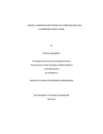
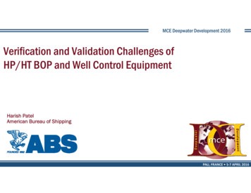
2007/4 PAGES 32 — 38Verification is a complex of activities with the aim of findingout and confirming that the standard corresponds to the specifiedrequirements. The result of the verification is a statement as towhether the given standard fulfils the requirements or not [1],[6].Calibration is a basic metrology activity; it is a specific kindof measurement using standards. Without the use of calibratedstandards, it is not possible to provide quality in the productionor even the credibility of the measured results [6]. With thecurrent development of progressive measuring technologiesand integrated measuring instruments (IMI) in surveying, itis necessary to devote enhanced and sustained attention tothe verification and calibration of geodetic instruments as aninseparable part of measurement.VERIFICATION AND CALIBRATION OFHORIZONTAL CIRCLES OF GEODETICINSTRUMENTSVerification of the quality of the divided circles of geodeticinstruments is not as frequent as verification of scales by othermeasures, e.g., linear. There are several reasons for this: the highdegree of accuracy from their production (the application of linemasks on the glass circles by optical theodolites and eventuallyby the creation of incremental line or code circles) – their rangeis 2cc - 8cc; the high costs for determining the periodical errorof a circle, the necessity of expensive testing equipment andthe possibility of decreasing the effect of error in the dividingof a circle by a suitable measuring technology for horizontaldirections [2].IMI divided circles are no longer produced on dividedinstruments, but are produced by an optic-electronic copy froma so-called maternity circle, which also has periodical errors.The amount and running of systematic and random errors canbe mathematically presented by the Fourier series. The resultsof testing have shown that the errors from dividing a code circle(maximal amplitudes) are an important factor of accuracy forelectronic instruments and can also be higher and less stable thanby optical theodolites [5].Currently, the most often used process for verification of thequality of horizontal circles and eventually the accuracy of anglemeasurements is a process according to STN ISO 8322, whichassumes measurement in two faces, four ranks and two series. Themeasurements have to be realized over two days.Each series of measurements consists of four temporarilyseparated groups of measurements of directions. After finishingthe measurement in the first rank, a 90-minute pause follows.The reading on the horizontal circle is moved about 50gon or 45 degrees after each rank. Part of the measurement is the registrationof actual meteorological conditions (temperature, atmosphericpressure and moisture). Through the automated registration of themeasured values, it is possible to automate the whole processingusing a computer.The accuracy of the angle measurements and eventually themeasurement of directions is characterized by the mean errorm α according to this norm. This error arises from the cooperation of the whole error range – the elementary errorsof the instrument, the person and the environment during themeasuring process.The process realized according to the above-mentioned adviceenables the determination out and confirmation that the standardcorresponds to the specified requirements – it enables itsverification.Fig. 1 Optical traverseFig. 2 EZB-3 standard equipment for the calibration of traversesCALIBRATION AND VERIFICATION OF HORIZONTAL CIRCLES OF ELECTRONIC.jezko 01.indd 33338. 11. 2007 12:09:40
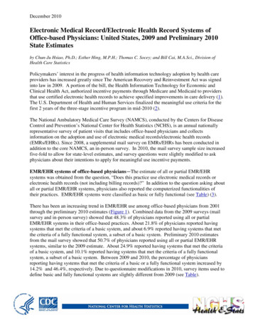
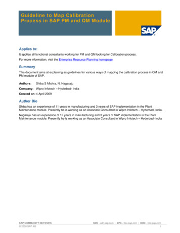
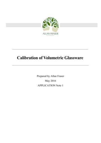
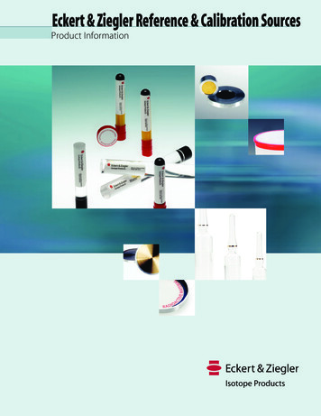
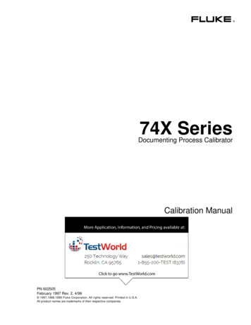
2007/4 PAGES 32 — 38EQUIPMENT FOR AUTOMATED CALIBRATION OFOPTIC TRAVERSES AND HORIZONTAL CIRCLESOF GEODETIC INSTRUMENTSOptical traverses are one of the parts of the primary standard ofa planar angle. It is a (mostly) ordinary n-edged prism, whosefunctional surfaces are planar and treated into the mirror’s reflection.Vertical lines to the functional surfaces create a schema of directions.The optical traverses (Fig.1) are produced with the functional surfacesof a number between 6 and 72; this means with nominal angles amongthe functional surfaces from 60 degrees up to 5 degrees. Opticaltraverses for metrological purposes are produced by only a few firmsin the world because their technical production is very difficult [4].Two methods are used for calibrating optical traverses, namely, themethod of two autocollimators and the method of dividing a table(circular equipment with a circled scale) with an autocollimator.The equipment for working on both the mentioned principles isa part of the primary planar angle standard at the Slovak Instituteof Metrology (SIM), which, in 1998, was acclaimed for the nationalstandard of the planar angle of the Slovak Republic. The primarystandard enables the calibration of optical traverses with a combinedstandard deviation of corrections of m 0.06” [4].The EZB-3 standard equipment for the automated calibration oftraverses is created by Zeiss Jena and is a turning dividing tablewith a servo-drive, on which a calibrated optical traverse is situated,along with a couple of photo-electronic autocollimators (Fig.2).These elements are situated on a basic cast iron disc with an antivibration arrangement.Both autocollimators in a basic position are aimed at the neighbouringfunctional surfaces of the traverse. During the step-by-step turningof the traverse, the autocollimators measure the deviations of theposition of the vertical lines to the functional surfaces of the traversein regard to the optical axis of the autocollimators.In order to calibrate the theodolites, the EZB-3 equipment fortraverse calibration was supplemented with a 72-edged opticaltraverse situated instead of a calibrated traverse. One of theautocollimators, which also serves as a part of the servo-driving ofthe turning of the dividing table, was aimed at the optical traverse.The calibrated instrument was centrally situated on the opticaltraverse, which had a mirror fixated on the alidade. The centringaccuracy of the instrument is given by the value of 0.1 mm (fixationwith a screw). The second autocollimator was situated on the basicboard in such a way that its optical axis was at the height of thetelescopic axis of the theodolite (Fig. 3).Before any measurement it is necessary to fulfill the adjustmentconditions described in detail in [4]. After adjustment of themeasuring formation, the autocollimator of the traverse is aimedat the required functional surface of the traverse by turning thecircular part of the table with the traverse and theodolite. Then withthe help of the reverse turning of the theodolite alidade, it is aimedat a subsidiary telescope mirror. The data from both autocollimatorsare read as is the value of the dividing circle of the theodolite witha given number of repetitions. The circular part of the table is turnedto the next required functional surface of the traverse, and the wholeprocess is repeated. The turning of the circular part of the tableabout the required angle concerns a slight turning for the aiming ofthe traverse autocollimator, and the reading of the data from bothautocollimators is automated.For these purposes the measured program of the traverse calibrationwas repaired as follows: one calibration step consists of scanningdata from both autocollimators and their transfer to a PC of themeasured system and of the following turning of the traverse withthe theodolite about the required angle (a multiple of 5 degrees)with a deviation of 0.1”.The correction from dividing the theodolite circle is given by thefollowing function(1)where: ki is the correction of dividing the theodolite circle at the ”i ” point of the dividing circle,Aj – reference angle of the traverse for surface ” j ”,kjP – correction of functional surface ” j ” of the traverse,Bi – value of dividing the theodolite circle at the ” i ” pointof the dividing circle,aj – reading of the autocollimator scale on the functionalsurface ” j ” of the traverse,bi – reading of the autocollimator scale at the ” i ” point ofthe dividing circle of the calibrated theodolite.Fig. 3 Calibration of Topcon GTS 6B instrument on the EZB – 334jezko 01.indd 34Provided that during the pointing the dividing circle of the calibratedtheodolite and the autocollimator scales are oriented as follows: theCALIBRATION AND VERIFICATION OF HORIZONTAL CIRCLES OF ELECTRONIC.8. 11. 2007 12:09:43
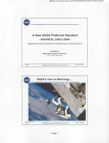
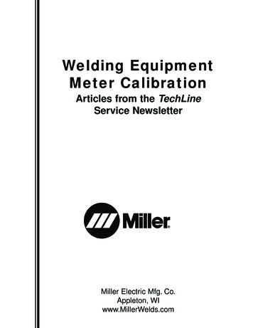
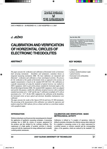
2007/4 PAGES 32 — 38Fig. 4 Graphic presentation of corrections of the horizontal circle of the Topcon GTS-6Areading value of the theodolite increases at the first traverse functionsurface and reading value of the autocollimators decreases, then thecorrection of the dividing circle of the theodolite is as follows:,(2)where: N is the number of functional surfaces of the traverse.Corrections determined in this way are important for theodoliteswith an unchanging position of the dividing circle. Knowing thesecorrections then enables the realization of the optimisation of themeasuring process using the theodolite. With theodolites, whichhave a the possibility of changing the position of the origin ofthe dividing circle, the behaviour of the corrections providesa concept about the behaviour of the errors of the readingsystem of the horizontal circle without any possibilities for theircorrection.According to the given formula (2), partial elements such as thestandard uncertainty of the traverse correction, the standarduncertainty of reading a divided theodolite circle, the standarduncertainty of reading the autocollimator on the functionalsurface of the traverse, the standard uncertainty of reading theautocollimator on the mirror of the theodolite, the effect of theparameters of the functional surface of the traverse on theautocollimator reading, and the effect of the parameters of thefunctional surface of the theodolite mirror on the autocollimatorreading have an effect on the uncertainty of the corrections [4].The effect of the partial uncertainties of the calibration equipmentis important only for the values of reading any uncertainty on thedividing theodolite circle under a value of 0.5” [4].CALIBRATION OF HORIZONTAL CIRCLESOF GEODETIC INSTRUMENTS ON EZB-3EQUIPMENTHorizontal circles of several optical and electronic instrumentswere calibrated on EZB-3 adapted standard equipment for thecalibration of theodolites (to illustrate, there are selected results ofthe calibration of Topcon GTS-6A and Leica TC 800 instrumentsfrom 2004, Figs. 4 and 5).CALIBRATION AND VERIFICATION OF HORIZONTAL CIRCLES OF ELECTRONIC.jezko 01.indd 35358. 11. 2007 12:09:45
2007/4 PAGES 32 — 38Fig. 5 Graphic presentation of corrections of the horizontal circle of the Leica TC 800Fig. 6 Regression polynomial for Topcon GTS-6A36jezko 01.indd 36CALIBRATION AND VERIFICATION OF HORIZONTAL CIRCLES OF ELECTRONIC.8. 11. 2007 12:09:47
2007/4 PAGES 32 — 38PROCESSING AND GRAPHIC PRESENTATION OFCALIBRATION RESULTSTab. 1Topcon GTS-6ARegression coefficient R2Type and regression 6525.0.97406.0.9740Leica TC 800Regression coefficient R2Type and regression 4485.0.84546.0.8458From the valuation of the calibration results, we also determinedthe regression curve, which also represents the calibration curve(function) for the individual instruments in this case. The testingof the outlying values was realized with the help of the McKaytest on an α 1% significance level [2], [7]. This means that witha probability of 99% and a risk of 1%, we can say that there are nooutlying values in the determined group of the correction valuesfor the horizontal angle. The regression analysis was realized usingExcel 2002, first as linear and then as non-linear up to the sixthorder. The most suitable order of regression was selected on thebasis of the R2 regression coefficient. The values of the regressioncoefficients are presented in Tab.1, and the running of the regressionpolynomials are presented on Figs. 6 and 7.Tab. 2Type of instrumentTopcon GTS-6ALeica TC 800Polynomial orderStandarddeviation [“]50.8760.8240.7450.73Fig. 7 Regression polynomial for Leica TC 800CALIBRATION AND VERIFICATION OF HORIZONTAL CIRCLES OF ELECTRONIC.jezko 01.indd 37378. 11. 2007 12:09:49
2007/4 PAGES 32 — 38CONCLUSIONin geodesy – a working measure with an irreplaceable place inmeasuring practice, which has to be calibrated and verified.The calibration described process provides: direct continuity on the primary standard of the planar angle, calibration of the horizontal circle of whole theodolites, the minimal calibration step is 5 or its integral multiple, the calibration (regression) polynomial for the horizontal circlesof geodetic instruments is a basic calibration result and introducesthe possibility of supplying dividing errors of the horizontalcircle of a geodetic instrument (Figs. 6 and 7).The results presented, which were achieved through calibration ofthe selected instruments, confirm their necessity and point at thecomplexity of the whole calibration process.The optical or electronic theodolite (in connection with a rangefinder such as IMI) introduces a basic angle and linear instrumentThis article is published as a part of Vega Grant project No.1/1153/04.The standard deviation in the determination was estimated accordingto the following formula [3]:(3)where: v are corrections of the measured values on the regressioncurve,n – number of node points,a – order of approximation.REFERENCES[1] BREZINA, I.: Basic Metrological Terminology. In: Metrologyin Geodesy. Bratislava, Department of Theoretical Geodesy,Faculty of Civil Engineering, Slovak University of Technology,2001, pp. 9 – 16 (in Slovak).[2] JEŽKO, J. – MOKROŠ, J. – PACKO, J.: Some KnowledgeGained from Calibration of the Horizontal Circles of GeodeticInstruments. In: INGEO 2002. Bratislava, Department ofSurveying, Faculty of Civil Engineering, Slovak University ofTechnology, 2002, pp. 187 – 194.[3] KUBÁČEK, L. – PÁZMAN, A.: Statistical Methods inMeasurement. Bratislava 1978 (in Slovak).38jezko 01.indd 38[4] MOKROŠ, J.: Calibration of the Horizontal Circle ofTheodolites. In: Metrology in Geodesy. Bratislava, Departmentof Theoretical Geodesy, Faculty of Civil Engineering, SlovakUniversity of Technology, 2001, pp. 123 – 130 (in Slovak).[5] SOKOL, Š. - MICHALČÁK, S.: Surveying. Angle Measurement.Slovak University of Technology, Bratislava, 1999, 245 pp. (inSlovak).[6] STN 01 0115 Terminology in Metrology. SÚTN, Bratislava2001, 40 pp. (in Slovak).[7] VYKUTIL, J.: Error Theory. ES VUT 1980, pp. 265 – 281 (inCzech).CALIBRATION AND VERIFICATION OF HORIZONTAL CIRCLES OF ELECTRONIC.8. 11. 2007 12:09:51
analysis using Excel 2002 software, first as a linear and later as a non-linear analysis with a graphical output. Ing. Ján Ježko, PhD. Senior lecturer at the Department of Land Surveying Research field : Calibration Surveying Instruments, Electronic Distance Measurement. Department of