Transcription
The Impact of theNew IEEE 1584-2018Standard onArc Flash Studies PresentedSous-titrebySimon Giard-Leroux, P.Eng.2019
Webinar Plan 1. Webinar Objectives 2. Changes in IEEE 1584-2018 3. Old Calculation Method in IEEE 1584-2002 4. New Calculation Method in IEEE 1584-2018 5. Parameter Sensitivity Analysis for IEEE 1584-2018 6. Conclusion & Recommendations 7. QuestionsExcellence in Engineering2
01Webinar Objectives
Webinar Objectives By the end of this webinar, participants will be able to: Define the steps required to perform arc flash calculations Identify the changes in the new IEEE 1584-2018 standard with regards to theIEEE 1584-2002 Understand the new calculation method in the IEEE 1584-2018 standard Know the impact of the parameters on the arc flash incident energy : VoltageEnclosure SizeElectrode ConfigurationElectrode GapFault CurrentWorking DistanceExcellence in Engineering4
02Changes inIEEE 1584-2018
IEEE 1584-2018: Changes Update of the arc flash calculation algorithm on which the CSA Z462 is based(Appendix D) First update since 2002, except for amendments in 2004 and 2011 The incident energy calculation formulas were revised and replaced by modelsbased on statistical analyses based on more than 1860 tests, while the 2002version was based on about 300 tests The electrode (busbar) configuration is now used as a parameter in theequations : VCB, VCBB, HCB, VOA, HOA The enclosure size of the equipment is now used in the calculations : height,width, depthExcellence in Engineering6
IEEE 1584-2018: Changes IEEE 1584 model application limits were extended 2002 Version: Voltage: 208 V to 15 kV, three-phase Short-circuit current: 700 A to 106 kA Distance between phases: 13 mm to 152 mm 2018 Version: Voltage: 208 V to 15 kV, three-phase Short-circuit current:– 208 V to 600 V: 500 A to 106 kA– 601 V to 15 kV: 200 A to 65 kA Distance between phases:– 208 V to 600 V: 6.35 mm to 76.2 mm– 601 V to 15 kV: 19.05 mm to 254 mm The system grounding (delta, floating wye, wye grounded with impedance,wye solidly grounded) is no longer considered in arc flash calculationsExcellence in Engineering7
IEEE 1584-2018: Changes 2 seconds limit for the duration of the arc fault still applies 2002 Version : "It is likely that a person exposed to an arc flash will move away quickly if it isphysically possible and two seconds is a reasonable maximum time for calculations." 2018 Version : "It is likely that a person exposed to an arc flash will move away quickly if it isphysically possible, and 2 s usually is a reasonable assumption for the arc duration todetermine the incident energy." Exception for small distributions is modified, the power limit of 125 kVA isreplaced by a fault current of 2 kA 2002 Version : "Equipment below 240 V need not be considered unless it involves at least one125 kVA or larger transformer in its immediate power supply." 2018 Version : "Sustainable arcs are possible but less likely in three-phase systems operatingat 240 V nominal or less with an available short-circuit current less than 2000 A."2 kA equivalent in transformer power rating208 V Secondary : 𝑆 Excellence in Engineering3 𝑉 𝐼𝑐𝑐 %𝑍 3 208 𝑉 2 𝑘𝐴 0.04 𝟐𝟗 𝒌𝑽𝑨8
IEEE 1584-2018: Changes Motor rated power limit of 50 hp is modified and now only refers to "largemotors", but other standards in reference still refer to the 50 hp limit 2002 Version : "The study must take into account all sources, including utilities, standby andpower generators, and large motors – those 37 kW (50 hp) and larger that contribute energy toshort circuits." 2018 Version : "Systems containing multiple sources of short-circuit current, such as generators,large motors, or more than one utility supply, can be more accurately modeled with a dynamicsimulation method. Methods may include multiple calculations to account for decaying short-circuitcurrent contributions from rotating equipment, and the effect on protective device opening timesand resulting incident energy." References : IEEE 1584.1-2013 : "The higher available fault current calculations should be based onall simultaneously operating large motors (greater than or equal to 50 hp) turned on,and the lower calculations should be based on no large motors running." IEEE 551-2006 (Violet Book) : "For application of ac medium-voltage circuit breakers,symmetrical (ac component) short-circuit current duties are calculated according toIEEE Std C37.010-1999 [ ]. The calculations omit all motors of less than 50 hp each." IEEE C37.010-2016 : "Neglect all three-phase induction motors below 37.5kW (50 hp)and all single-phase motors."Excellence en ingénierie9
IEEE 1584-2018: Changes Recommended method for 15 kV is no longer specifically the Lee method,therefore other methods such as ArcPro now are more relevant 2002 Version : "For cases where voltage is over 15 kV, or gap is outside the range of the model,the theoretically derived Lee method can be applied and it is included in the IEEE Std 1584-2002Incident Energy Calculators." 2018 Version : "There are alternative calculation methods for system parameters that fall outsideof the range of the model. However, no particular recommendation can be made because thereare other application details such as bolted fault current levels, voltage, gap length, operatingfrequency, number of phases, types of faults, etc. The user is advised to properly researchalternative calculation methods and their application viabilities." The Lee method was far too conservative compared to other software (ie.ArcPro) for voltages 15 kVExcellence in Engineering10
IEEE 1584-2018: Changes Single-phase systems: still not explicitly covered by IEEE 1584, but aconservative method is given 2002 Version : "Single-phase ac systems [.] are not included in this guide." 2018 Version : "This model does not cover single-phase systems. Arc-flash incident energy testingfor single-phase systems has not been searched with enough detail to determine a method forestimating the incident energy. Single-phase systems can be analyzed by using the single-phasebolted fault current to determine the single-phase arcing current (using the equations provided in 4.4and 4.10). The voltage of the single-phase system (line-to-line, line-to-ground, center tap voltage,etc.) can be used to determine the arcing current. The arcing current can then be used to fnd theprotective device opening time and incident energy by using the three-phase equations provided inthis guide. The incident Energy result is expected to be conservative." DC networks: still not explicitly covered by IEEE 1584, publications (i.e. Doan)are now added as references 2002 Version : "There is ongoing testing at dc, but it was not used in this analysis. Therefore dc andother frequencies of operation such as 400 Hz are not included in the IEEE Std 1584-2002empirically derived model.", " [.] DC systems are not included in this guide." 2018 Version : "Arc-flash incident energy calculation for DC systems is not part of this model.However, publication references (Ammerman et al. [B1], Das [B16], [B17], Doan [B25], Klement[B62]) provide some guidance for incident energy calculation."Excellence in Engineering11
03Old CalculationMethod inIEEE 1584-2002
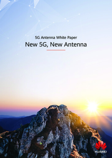
2002 Version: Old calculation method 1. Determine the arcing current Iarc 1.1. For V 1 kV : Equations 1 and 3 1.2. For V 1 kV : Equations 2 and 3 2. Determine the arc fault duration t with the time-current curve 3. Determine the normalized incident energy En : Equations 4 and 5 4. Determine the incident energy E : Equation E.1 5. Determine the arc flash boundary AFB : Equation E.3 6. If V 1 kV : 6.1 Determine the minimum arcing current : Iarc min 85 % x Iarc 6.2. Redo 2., 3., 4. and 5. with Iarc min, then tmin, Emin and AFBmin are obtained 5.2. The final incident energy is the highest value between E and Emin 5.3. The final arc flash boundary is the highest value between AFB and AFBminExcellence in Engineering13
1. Determine the arcing current IarcExcellence in Engineering14
2. Determine the arc fault duration t with the time-current curveArc currentIarcArc faultdurationtExcellence in Engineering15
3. Determine the normalized incident energy En : Equations 4 and 5Excellence in Engineering16
4. Determine the incident energy E : Equation E.1Excellence in Engineering17
5. Determine the arc flash boundary AFB : Equation E.3Excellence in Engineering18
04New CalculationMethod inIEEE 1584-2018
2018 Version: New calculation method 1. Determine the arcing current Iarc 1.1. Determine the electrode configuration 1.2. For 600 V Voc 15 kV: Equations 1, 16, 17, 18 1.3. For 208 V voc 600 V: Equations 1, 25 2. Determine the arc fault duration T with the time-current curve 3. Determine the incident energy E 3.1. Determine the enclosure size correction factor CF : Equations 14, 15 3.2. For 600 V Voc 15 kV: Equations 3, 4, 5, 19, 20, 21 3.3. For 208 V voc 600 V: Equation 6 4. Determine the arc flash boundary AFB 4.1. For 600 V Voc 15 kV: Equations 7, 8, 9, 22, 23, 24 4.2. For 208 V voc 600 V: Equation 10 5. Determine the minimum arcing current Iarc min : Equation 2 5.1. Redo 2., 3. and 4. with Iarc min, then Tmin, Emin and AFBmin are obtained 5.2. The final incident energy is the highest value between E and Emin 5.3. The final arc flash boundary is the highest value between AFB and AFBminExcellence in Engineering20
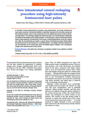
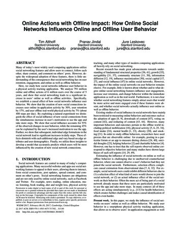
1.1 Determine the electrode configurationVCB:Vertical conductors /electrodes inside ametal box / enclosureVCBB:Vertical conductors /electrodes terminated inan insulating barrierinside a metal box /enclosureExcellence in Engineering21
1.1 Determine the electrode configurationHCB:Horizontal conductors /electrodes inside ametal box / enclosureVOA:Vertical conductors /electrodes in open airHOA:Horizontal conductors /electrodes in open airExcellence in Engineering22
1.2. Iarc For 600 V Voc 15 kV: Equations 1, 16, 17, 18Typical value asper Table 8 oractual equipmentvalueThese coefficientsdepend on theelectrodeconfiguration(VCB, VCBB,HCB, VOA, HOA)If 600 V Voc 2.7 kV:If Voc 2.7 kV:Excellence in Engineering23
1.3. Iarc For 208 V Voc 600 V: Equations 1, 25Typical value asper Table 8 oractual equipmentvalueThese coefficientsdepend on theelectrodeconfiguration(VCB, VCBB,HCB, VOA, HOA)Excellence in Engineering24
2. Determine the arc fault duration T with the time-current curveArc currentIarcArc faultdurationTExcellence in Engineering25
3.1. Determine the enclosure size correction factor CF "Shallow" enclosure : if voltage 600 V, height 20 inches, width 20 inchesand depth 8 inches "Typical" enclosure : all other casesIf "Shallow":If "Typical":Excellence in Engineering26
3.2. E for 600 V Voc 15 kV: Equations 3, 4, 5, 19, 20, 21Excellence in Engineering27
3.2. E for 600 V Voc 15 kV: Equations 3, 4, 5, 19, 20, 21If 600 V Voc 2.7 kV:If Voc 2.7 kV:Excellence in Engineering1 𝑐𝑎𝑙Τ𝑐𝑚21 𝐽Τ𝑐𝑚2 4,18428
3.3. E for 208 V Voc 600 V: Equation 6Excellence in Engineering29
4.1. AFB for 600 V Voc 15 kV: Equations 7, 8, 9, 22, 23, 24Excellence in Engineering30
4.1. AFB for 600 V Voc 15 kV: Equations 7, 8, 9, 22, 23, 24If 600 V Voc 2.7 kV:If Voc 2.7 kV:Excellence in Engineering31
4.2. AFB for 208 V Voc 600 V: Equation 10Excellence in Engineering32
5. Determine the minimum arcing current Iarc min : Equation 2 5.1. Redo 2., 3. and 4. with Iarc min, thenTmin, Emin and AFBmin are obtained 5.2. The final incident energy is the highest value between E and Emin 5.3. The final arc flash boundary is the highest value between AFB and AFBminExcellence in Engineering33
05Parameter SensitivityAnalysis for IEEE1584-2018
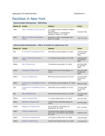
IEEE 1584-2018: Sensitivity Analysis The relationship between the inputs of the IEEE 1584-2018 equations and thearc flash incident energy can be hard to predict because of the complexity of theequations A sensitivity analysis tool using numerical methods was developed in Python inorder to evaluate the impact of the parameters on the arc flash incident energy 4 examples are evaluated : 15 kV Switchgear 600 V Switchgear 208 V Panel (Shallow) 15 kV Breaker (Outdoor)Excellence in Engineering35
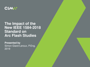
Example #1: 15 kV SwitchgearExcellence in Engineering36
Example #1: 15 kV SwitchgearParameterValueUpstream Protection2 s rule appliedVoltageIndependent Variable ‘x’Enclosure Height1143 mm (45 in)Enclosure Width762 mm (30 in)Enclosure Depth762 mm (30 in)Electrode Gap152 mm (6 in)Bolted Fault Current10 kAWorking Distance0.914 m (36 in)Excellence in Engineering37
Example #1: 15 kV SwitchgearParameterValueUpstream Protection2 s rule appliedVoltage13.8 kVEnclosure HeightIndependent Variable ‘x’Enclosure Width762 mm (30 in)Enclosure Depth762 mm (30 in)Electrode Gap152 mm (6 in)Bolted Fault Current10 kAWorking Distance0.914 m (36 in)Excellence in Engineering38
Example #1: 15 kV SwitchgearParameterValueUpstream Protection2 s rule appliedVoltage13.8 kVEnclosure Height1143 mm (45 in)Enclosure WidthIndependent Variable ‘x’Enclosure Depth762 mm (30 in)Electrode Gap152 mm (6 in)Bolted Fault Current10 kAWorking Distance0.914 m (36 in)Excellence in Engineering39
Example #1: 15 kV SwitchgearParameterValueUpstream Protection2 s rule appliedVoltage13.8 kVEnclosure Height1143 mm (45 in)Enclosure Width762 mm (30 in)Enclosure DepthIndependent Variable ‘x’Electrode Gap152 mm (6 in)Bolted Fault Current10 kAWorking Distance0.914 m (36 in)Excellence in Engineering40
Example #1: 15 kV SwitchgearParameterValueUpstream Protection2 s rule appliedVoltage13.8 kVEnclosure Height1143 mm (45 in)Enclosure Width762 mm (30 in)Enclosure Depth762 mm (30 in)Electrode GapIndependent Variable ‘x’Bolted Fault Current10 kAWorking Distance0.914 m (36 in)Excellence i
Identify the changes in the new IEEE 1584-2018 standard with regards to the IEEE 1584-2002 Understand the new calculation method in the IEEE 1584-2018 standard Know the impact of the parameters on the arc flash incident energy : Voltage Enclosure Size Electrode Configuration Electrode Gap Fault Current Working Distance