Transcription
Fundamental ElectricalConcepts
Electric Charge (Q) Characteristic of subatomic particles thatdetermines their electromagnetic interactions An electron has a -1.602 10-19 Coulomb charge The rate of flow of charged particles is calledcurrent
Current Current (Number of electrons that pass inone second) (charge/electron) -1 ampere (6.242 1018 e/sec) (-1.602 10-19Coulomb/e) Notice that an ampere Coulomb/second The negative sign indicates that the current inside isactually flowing in the opposite direction of theelectron flowElectronsCurrent
Current i dq/dt – the derivitive or slope of the chargewhen plotted against time in seconds Q i dt – the integral or area under thecurrent when plotted against time in secondsCurrentamps4321Q delivered in 0-5 sec 12.5 Coulombs5 sec
AC and DC Current DC Current has a constant value AC Current has a value that changes sinusoidally Notice that AC currentchanges in value anddirection No net charge istransferred
Why Does Current Flow? A voltage source provides the energy (orwork) required to produce a current Volts joules/Coulomb dW/dQ A source takes charged particles (usuallyelectrons) and raises their potential so theyflow out of one terminal into and through atransducer (light bulb or motor) on their wayback to the source’s other terminal
Terms to Remember The Source can be any source of electrical energy. In practice, there arethree general possibilities: it can be a battery, an electrical generator, orsome sort of electronic power supply. The Load is any device or circuit powered by electricity. It can be as simple asa light bulb or as complex as a modern high-speed computer. (Path) a wire or pathway which will allow electron to flow throughout acircuit. Electricity can be described as the flow of charged particles. If theparticles accumulate on an object, we term this static electricity. (Direct Current) An electrical current that travels in one direction and usedwithin the computer's electronic circuits. (Alternating Current) The common form of electricity from power plant tohome/office. Its direction is reversed 60 times per second. Circuit is a conducting path for electrons.Copyright Texas Education Agency, 2011.All rights reserved.7
Voltage Voltage is a measure of the potential energythat causes a current to flow through atransducer in a circuit Voltage is always measured as a differencewith respect to an arbitrary common pointcalled ground Voltage is also known as electromotive forceor EMF outside engineering
What is Ohm’s Law?Ohm's Law states that, at constant temperature, the electriccurrent flowing in a conducting material is directly proportionalto the applied voltage, and inversely proportional to theResistance.Why is Ohms Law important?Ohm’s Law is the relationship between power, voltage, currentand resistance. These are the very basic electrical units wework with. The principles apply to alternating current (ac),direct current (dc), or radio frequency (rf) .Copyright Texas Education Agency, 2011.All rights reserved.9
Ohm’s LawI V/RGeorg Simon Ohm (1787-1854)I Current (Amperes) (amps)V Voltage (Volts)R Resistance (ohms)
Characteristics of Ohm’s LawVoltage: Difference of potential, electromotive force, ability to dowork.Unit of measure Volt Symbol V (Current: Flow of electrons Unitof measure Ampere Symbol IResistance: Opposition to current flow Unit of measure Ohmoften seen as the Greek letter Omega Symbol RCopyright Texas Education Agency, 2011.All rights reserved.11
A Circuit Current flows from the higher voltage terminal of the sourceinto the higher voltage terminal of the transducer beforereturning to the sourceI TransducerVoltage The source expendsenergy & the transducerconverts it intosomething useful- SourceVoltage-I
circuit diagramScientists usually draw electric circuits using symbols;celllampswitchwires
Simple Circuits Series circuit– All in a row– 1 path for electricity– 1 light goes out and thecircuit is broken Parallel circuit– Many paths for electricity– 1 light goes out and theothers stay on
Series and Parallel Circuits Series Circuits– only one end of each component is connected– e.g. Christmas tree lights Parallel Circuits– both ends of a component are connected– e.g. household lighting
Passive Devices A passive transducer device functions onlywhen energized by a source in a circuit Passive devices can be modeled by a resistance Passive devices always draw current so thatthe highest voltage is present on the terminalwhere the current enters the passive device V 0I 0- Notice that the voltage ismeasured across the device Current is measuredthrough the device
Active Devices Sources expend energy and are consideredactive devices Their current normally flows out of theirhighest voltage terminal Sometimes, when there are multiple sourcesin a circuit, one overpowers another, forcingthe other to behave in a passive manner
Power The rate at which energy is transferred froman active source or used by a passive device P in watts dW/dt joules/second P V I dW/dQ dQ/dt volts amps watts W P dt – so the energy (work in joules) isequal to the area under the power in wattsplotted against time in seconds
Conservation of Power Power is conserved in a circuit - P 0 We associate a positive number for power aspower absorbed or used by a passive device A negative power is associated with an activedevice delivering powerI V-If I 1 ampV 5 voltsThen passiveP 5 watts(absorbed)If I -1 ampV 5 voltsThen activeP -5 watts(delivered)If I -1 ampV -5 voltsThen passiveP 5 watts(absorbed)
Example A battery is 11 volts and as it is charged, itincreases to 12 volts, by a current that startsat 2 amps and slowly drops to 0 amps in 10hours (36000 seconds) The power is found by multiplying the currentand voltage together at each instant in time In this case, the battery (a source) is acting likea passive device (absorbing energy)
Voltage, Current & Power
In this second example, we will calculate the amount of resistance (R) in acircuit, given values of voltage (E) and current (I):What is the amount of resistance (R) offered by the lamp?Copyright Texas Education Agency, 2011.All rights reserved.22
In the last example, we will calculate the amount of voltage supplied by abattery, given values of current (I) and resistance (R):What is the amount of voltage provided by the battery?Copyright Texas Education Agency, 2011.All rights reserved.23
Resistance Property of a device that indicates how freely it willallow current to flow given a specific voltageapplied. If low in value, current flows more freely. Measured in ohms (Ω V/A or KΩ V/mA)R Voltage or V I R This is Ohm’s Law!CurrentI Obeys the passive sign conventionVif I 0 then V 0
Resistors Resistors are devices that are used in a varietyof circuits to make the currents and voltageswhat you desire They are color-coded and come in varioustolerances, 1%, , 5% and , 10% are mostcommon
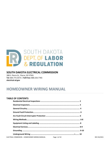
Resistor Color Code56 * 10 kΩ 560 kΩ237 * 1 Ω 237 Ωhttp://www.elexp.com/t resist.htm
Conductance (G) Conductance is the reciprocal of resistanceIts unit is the siemen amps/volts 1/ΩG I/V 1/RAn equivalent measure of how freely a currentis allowed to flow in a device
Resistivity (ρ) Property of a material that indicates howmuch it will oppose current flow R (ρ · length) / (cross sectional area) Units are ohms · meters (Ω · m) As the wire gets bigger, so does the crosssection making the resistance smaller As the length gets longer, the resistance goesup proportionately
Conductors Materials with electrons that are looselybound to the nucleus and move easily(usually one electron in the outer shell) Their low resistance goes up as thematerial is heated, due to the vibration ofthe atoms interfering with the movementof the electrons The best conductors are superconductors attemperatures near 0o Kelvin
Semiconductors Materials with electrons that are boundmore tightly than conductors (usually 4electrons in the outer shell) Impurities are added in controlled amountsto adjust the resistivity down Semiconductors become better conductorsat higher temperatures because the addedenergy frees up more electrons (eventhough the electron flow is impeded by theincreased atomic vibration)
Insulators Materials that have all 8 electrons in the outershell tightly bound to the nucleus It takes high temperatures or very high electricfields to break the atomic bonds to free upelectrons to conduct a current Very high resistivities and resistances
Resistivity of Materials Glass Gold Silver Silicon Aluminum CopperPut a number 1 besidethe material thatis the best conductor,a 2 next to thematerial next mostconductive, etc.
Resistivity of Materials1 Silver - A conductor - ρ 1.64 ·10-8 ohm-m2 Copper - A conductor - ρ 1.72·10-8 ohm-m3 Gold – A conductor - ρ 2.45·10-8 ohm-m4 Aluminum - A conductor - ρ 2.8·10-8 ohm-m5 Silicon - A semiconductor - ρ 6.4 ·102 ohm-m6 Glass – An insulator – ρ 1012 ohm-m
Example A round wire has a radius of 1 mm 10-3mThe wire is 10 meters longThe wire is made of copperR (1.72 · 10-8 Ω·m · 10 m) /( π ·(10-3m) 2 )R 0.0547 ΩThis is negligible in most circuits whereresistances are often thousands of ohms
Power used by Resistors We saw that P I VIf by Ohm’s law, V I R, then P I2 ROr since I V /R, then P V2 / RSince resistance is always positive for passivedevices, then power is always positive(meaning that power is always absorbed orused)
Kirchoff’s Laws
Circuit Definitions Node – any point where 2 or more circuitelements are connected together– Wires usually have negligible resistance– Each node has one voltage (w.r.t. ground) Branch – a circuit element between twonodes Loop – a collection of branches that form aclosed path returning to the same nodewithout going through any other nodes orbranches twice
Example How many nodes, branches & loops?R1 -VsIsR2R3Vo-
Example Three nodesR1 -VsIsR2R3Vo-
Example 5 BranchesR1 -VsIsR2R3Vo-
Example Three Loops, if starting at node AABR1 -VsIsR2R3Vo-C
Kirchoff’s Voltage Law (KVL) The algebraic sum of voltages aroundeach loop is zero– Beginning with one node, add voltages acrosseach branch in the loop (if you encounter a sign first) and subtract voltages (if youencounter a – sign first) Σ voltage drops - Σ voltage rises 0 Or Σ voltage drops Σ voltage rises
Example Kirchoff’s Voltage Law around 1st LoopAI1 I1R1-BR1I2 -Vs IsR2 I2R2R3Vo-CAssign current variables and directionsUse Ohm’s law to assign voltages and polarities consistent withpassive devices (current enters at the side)
Example Kirchoff’s Voltage Law around 1st LoopAI1 I1R1-BR1I2 -Vs IsR2 I2R2R3Vo-CStarting at node A, add the 1st voltage drop: I1R1
Example Kirchoff’s Voltage Law around 1st LoopAI1 I1R1-BR1I2 -Vs IsR2 I2R2R3Vo-CAdd the voltage drop from B to C through R2: I1R1 I2R2
Example Kirchoff’s Voltage Law around 1st LoopAI1 I1R1-BR1I2 -Vs IsR2 I2R2R3Vo-CSubtract the voltage rise from C to A through Vs: I1R1 I2R2 – Vs 0Notice that the sign of each term matches the polarity encountered 1st
Circuit Analysis When given a circuit with sources andresistors having fixed values, you can useKirchoff’s two laws and Ohm’s law todetermine all branch voltages and currentsVAB - AIB7Ω 3Ω12 v-VBC-C
Circuit Analysis By Ohm’s law: VAB I·7Ω and VBC I·3ΩBy KVL: VAB VBC – 12 v 0Substituting: I·7Ω I·3Ω -12 v 0Solving: I 1.2 A V ABAIB7Ω 3Ω12 v-VBC-C
Circuit Analysis Since VAB I·7Ω and VBC I·3Ω And I 1.2 A So VAB 8.4 v and VBC 3.6 v VAB -AIB7Ω 3Ω12 v-VBC-C
Series Resistors KVL: I·10Ω – 12 v 0, So I 1.2 A From the viewpoint of the source, the 7and 3 ohm resistors in series areequivalent to the 10 ohmsI 12 v-10ΩI·10Ω-
Series Resistors To the rest of the circuit, series resistorscan be replaced by an equivalentresistance equal to the sum of all resistorsSeries resistors (same current through all)II.Σ Rseries
Kirchoff’s Current Law (KCL) The algebraic sum of currents entering anode is zero– Add each branch current entering the nodeand subtract each branch current leaving thenode Σ currents in - Σ currents out 0 Or Σ currents in Σ currents out
Example Kirchoff’s Current Law at BABI1R1I2 -Vs I3IsR2R3Vo-CAssign current variables and directionsAdd currents in, subtract currents out: I1 – I2 – I3 Is 0
Circuit AnalysisAI110 A 8Ω-I2 4Ω-VAB-BBy KVL: - I1 8Ω I2 4Ω 0Solving:I2 2 I 1By KCL:10A I1 I2Substituting:10A I1 2 I1 3 I1So I1 3.33 A and I2 6.67 AAnd VAB 26.33 volts
Circuit AnalysisA 10 A2.667ΩVAB-BBy Ohm’s Law: VAB 10 A 2.667 ΩSo VAB 26.67 voltsReplacing two parallel resistors (8 and 4 Ω)by one equivalent one produces the sameresult from the viewpoint of the rest of thecircuit.
Parallel Resistors The equivalent resistance for any numberof resistors in parallel (i.e. they have thesame voltage across each resistor):1Req 1/R1 1/R2 1/RN For two parallel resistors:Req R1 R2/(R1 R2)
Example CircuitSolve for the currents through each resistorAnd the voltages across each resistor
Example Circuit I1 10Ω I2 8Ω- I3 6Ω I3 4Ω-Using Ohm’s law, add polarities andexpressions for each resistor voltage
Example Circuit I1 10Ω I2 8Ω- I3 6Ω I3 4Ω-Write 1st Kirchoff’s voltage law equation-50 v I1 10Ω I2 8Ω 0
Example Circuit I1 10Ω I2 8Ω- I3 6Ω I3 4Ω-Write 2nd Kirchoff’s voltage law equation-I2 8Ω I3 6Ω I3 4Ω 0or I2 I3 (6 4)/8 1.25 I3
Example CircuitAWrite Kirchoff’s current law equation at A I1 – I2 - I3 0
Example Circuit We now have 3 equations in 3 unknowns,so we can solve for the currents througheach resistor, that are used to find thevoltage across each resistor Since I1 - I2 - I3 0, I1 I2 I3 Substituting into the 1st KVL equation-50 v (I2 I3) 10Ω I2 8Ω 0or I2 18 Ω I3 10 Ω 50 volts
Example Circuit But from the 2nd KVL equation, I2 1.25 I3 Substituting into 1st KVL equation:(1.25 I3) 18 Ω I3 10 Ω 50 voltsOr: I3 22.5 Ω I3 10 Ω 50 voltsOr: I3 32.5 Ω 50 voltsOr: I3 50 volts/32.5 ΩOr: I3 1.538 amps
Example Circuit Since I3 1.538 ampsI2 1.25 I3 1.923 amps Since I1 I2 I3, I1 3.461 amps The voltages across the resistors:I1 10Ω 34.61 voltsI2 8Ω 15.38 voltsI3 6Ω 9.23 voltsI3 4Ω 6.15 volts
Example CircuitSolve for the currents through each resistorAnd the voltages across each resistor usingSeries and parallel simplification.
Example CircuitThe 6 and 4 ohm resistors are in series, soare combined into 6 4 10Ω
Example CircuitThe 8 and 10 ohm resistors are in parallel, soare combined into 8 10/(8 10) 14.4 Ω
Example CircuitThe 10 and 4.4 ohm resistors are in series, soare combined into 10 4 14.4Ω
Example Circuit I1 14.4Ω-Writing KVL, I1 14.4Ω – 50 v 0Or I1 50 v / 14.4Ω 3.46 A
Example Circuit 34.6 v - 15.4 v-If I1 3.46 A, then I1 10 Ω 34.6 vSo the voltage across the 8 Ω 15.4 v
Example Circuit 34.6 v - 15.4 v-If I2 8 Ω 15.4 v, then I2 15.4/8 1.93 ABy KCL, I1-I2-I3 0, so I3 I1–I2 1.53 A
Circuits with DependentSources
Circuit with Dependent SourcesV1 60 volts because the 20Ω resistor is inparallel; by Ohm’s law, V1 I2·20Ω;so I2 V1/20Ω 60v/20Ω 3 A
Circuit with Dependent SourcesIf I2 3 A, then the 5Ω·I2 dependent sourceis 15 volts and if V1 60 v., then the V1/4Ωdependent source is 15 A
Circuit with Dependent SourcesWriting Kirchoff’s Voltage law around theoutside loop, -60 v 5Ω·I2 5Ω·I3 0where I2 3 A, so I3 (60–15)v / 5Ω 9 A
Circuit with Dependent SourcesWriting Kirchoff’s Current law at BI4 I3 V1/4 0 (all leaving node B)Since V1/4Ω 15 A and I3 9 A, I4 -24 A
Circuit with Dependent SourcesWriting Kirchoff’s Current law at AI4 I1 – I2 0Since I2 3 A and I4 -24 A, I1 27 A
Circuit with Dependent SourcesI4 -24AI1 27AI1/4Ω 15AV2 45v60 v source generating, P -27A·60v -1620 watts5·I2 source absorbing, P 24A·15v 360 wattsV1/4 source absorbing, P 15A·45v 675watts
Circuit with Dependent SourcesI3 9AV1 60vI2 3AV2 45v20 Ω resistor absorbing, P 3A·60v 180 watts5 Ω resistor absorbing, P 9A·45v 405 watts-1620 w 360 w 675 w 180 w 405 w 0
VA 28 voltsFind I12 Amps by Ohm’s law (I2 14 28)Find I22 Amps by KCL (4-I1-I2 0)Find VB24 volts by KVL (-I1 14 I2 2 VB 0)Find I36 Amps by Ohm’s law (I3 4 24)Find I44 Amps by KCL (I2 I4-I3 0)
Sources in Series -V1 - -V2V1 V2Voltage sourcesIn series addalgebraically
Sources in Series -V1 - V2V1-V2Start at the topterminal and add.If hit a ( V1)If you hit a – (-V2)
Sources in Series -8·Vx - V28·Vx-V2If one source isdependent, thenso is the equivalent
Sources in SeriesIsIsIsCurrent sources inseries must be thesame value anddirection
Sources in ParallelCurrent sources in parallel add algebraicallyI1I2I1 I2
Sources in ParallelCurrent sources in parallel add algebraicallyI1I2-I1 I2
Sources in ParallelIf any source is dependent, then thecombination is also dependentI15·Ix-I1 5·Ix
Sources in ParallelVoltage sources in parallel must be the samevalue and same direction -Vs -Vs -Vs
Source Transformation
Source Transformation Practical voltage sources are current limited andwe can model them by adding a resistor inseries Practical SourceRSIL -VsRL VL- We want to create an equivalent using a currentsource and parallel resistance for any RL
Source Transformation VL and IL must be the same in both circuitsfor any RLPractical SourceILIpRpRL VL-
Source Transformation VL and IL must be the same in both circuitsfor RL 0, or a short circuitPractical SourceILIpRpRL 0 VL- Ip IL and VL 0
Source Transformation Now look at the voltage source in serieswith the resistor with a short circuitPractical SourceRSIL -VsRL 0 VL- IL Vs/Rs and VL 0 So Ip Vs/Rs
Source Transformation VL and IL must also be the same in bothcircuits for RL , or an open circuitPractical SourceILIpRpRL VL- IL 0 and VL Ip·Rp
Source Transformation Now look at the voltage source in serieswith the resistor with an open circuitPractical SourceRSIL -VsRL VL- IL 0 and VL Vs, so Vs Ip·Rp If Ip Vs/Rs, then Rp Rs
Example We can transform the voltage source10Ω I1 -20v4A15Ω6ΩVo- Why? Gets all components in parallel
Example We can combine sources and resistors 20v/10Ω 2A4A10Ω15Ω6ΩVo- Ieq 2A 4A 6A, Req 3Ω
Example Vo 6A· 3Ω 18 v 6A3ΩVo-
Example Going back to the original circuit, Vo 18 v10Ω4AI1 -20v15Ω18/15 1.2A6Ω 18/6 3AVo 18 v- KCL: I1 4A - 1.2A - 3A 0, so I1 0.2A
Example We can transform the current source afterfirst combining parallel resistances10Ω -20v4A15Ω6ΩVo- Why? Gets all components in series
Example We can transform the current source afterfirst combining parallel resistances10Ω -20v4A30/7ΩVo- Req 6·15/(6 15) 30/7 Ω
Example We can now add the series voltagesources and resistances30/7Ω10Ω -I120v120/7v - Rtotal 100/7 Ω and Vtotal 20/7 volts
Example We can easily solve using KVL for I1100/7 Ω -I120/7 v I1 20/7 100/7 0.2 A
Voltage & Current Division
Voltage Division We could have a circuit with multipleresistors in series where we want to beable to find the voltage across any resistor.R1I -Ri. Vi -Vs Clearly Req Σ Ri, and I Vs/Req So Vi I·Ri Vs ·(Ri/Req)Rn
Voltage Division Application You have a 12 volt source, but somedevices in your circuit need voltages of 3and 9 volts to run properly.R1I -VsRi. Vi Rn You can design a voltage divider circuit toproduce the necessary voltages
Voltage Division Application To get 3, 6 and 3 across the threeresistors, any R, 2·R and R could be usedR 3v -12 v2·RA 9v 6v- BR- 9 volts is available at A, 3 volts at B3v-
Wheatstone Bridge This circuit is often used to measureresistance or convert resistance into avoltage.300Ω100Ω 100v- VAB -ARB500Ω
Wheatstone Bridge Using the voltage divider at A, VAD 100 v R/(100 R)Ω300Ω100Ω 100v- VAB -AB500ΩRD
Wheatstone Bridge Find the Voltage at B, using the voltagedivider theorem300Ω100Ω 100v- VAB -ARB500Ω
Wheatstone Bridge VBD 100 v 500Ω/(300 500)Ω 62.5 v300Ω100Ω 100v- VAB -AB500ΩRD
Wheatstone Bridge Let’s find the relationship between VAB & R VAB VAD – VBD 100 R/(100 R) – 62.5300Ω100Ω 100v- VAB -AB500ΩRD
Wheatstone Bridge The Wheatstone bridge is consideredbalanced when VAB 0 v. Find R300Ω R 167Ω100Ω 100v- VAB -ARB500Ω
Wheatstone Bridge
Current Division What if we want to find the current through anyparallel resistor?. IsR1RiIiRnV- Req 1 / Σ(1/Ri) and V Is·Req So Ii V / Ri Is·(Req/Ri)
Wheatstone Bridge The 10 A current source divides betweenthe two branches of the bridge circuit300Ω100Ω10 AI1I2 VAB 500Ω100ΩD
Wheatstone Bridge First, simplify by combining the seriesresistances in each branch of the bridge300Ω100Ω10 AI1I2 VAB 500Ω100ΩD
Wheatstone Bridge First, simplify by combining the seriesresistances in each branch of the bridgeI110 A100 100ΩI2300 500Ω
Wheatstone Bridge Find the parallel equivalent resistance Req 200 800/(200 800) Ω 160 ΩI110 A100 100ΩI2300 500Ω
Wheatstone Bridge I1 10 A (160/200) 8 A I2 10 A (160/800) 2 AI110 A100 100ΩI2300 500Ω
Voltage vs Current Division Voltage Division Current Division Vi Vs · Ri/ReqReq Σ RiRi/Req 1Vi VsSeries resistors onlyIi Is · Req/RiReq 1 Σ (1/Ri)Req/Ri 1Ii IsParallel resistors only
Application A practical source of 12 volts has a 1Ωinternal resistance. Design a voltagedivider that will be used to power up to ten6 volt light bulbs in parallel.1Ω12 v -R1R2100Ω.10 lights100Ω100Ω
Application The voltage across each bulb must bewithin the range of 5.5 to 6 volts in orderfor the bulbs to be bright enough. Find R1and R2.1Ω12 v -R1R2100Ω.10 lights100Ω100Ω
Application With no bulbs, the maximum voltage isobtained:12v·R2Vbulb 6.0 v 1Ω R1 R21Ω12 v -R1R2 Vbulb-
Application The parallel combination of ten 100Ωbulbs is 10Ω, the parallel combination withR2 is10·R2/(10 R2)Ω10·R2/(10 R2)1Ω12 v -R1R2100Ω.10 lights100Ω100Ω Vbulb-
Application Using the voltage divider and the minimumvoltage allowed:12v·10·R2/(10 R2)Vbulb 5.5 v 1Ω R1 10·R2/(10 R2)1Ω12 v -R1R2100Ω.10 lights100Ω100Ω Vbulb-
Solution Solving the two equations simultaneously,R1 .82Ω and R2 1.82Ω With 10 bulbs, R2 in parallel with ten 100Ωresistors would be 1.54Ω Using the voltage divider, with 10 bulbsVbulb 12 1.54Ω (1 .82Ω 1.54Ω) 5.5 v Using the voltage divider, with no bulbsVbulb 12 1.82Ω (1 .82Ω 1.82Ω) 6.0 v
Capacitors andRC circuits
Capacitors Composed of two conductive plates separatedby an insulator (or dielectric).– Commonly illustrated as two parallel metal platesseparated by a distance, d.C ε A/dwhere ε εr εoεr is the relative dielectric constantεo is the vacuum permittivity
Effect of Dimensions Capacitance increases with– increasing surface area of the plates,– decreasing spacing between plates, and– increasing the relative dielectric constant of theinsulator between the two plates.
Types of Capacitors Fixed Capacitors– Nonpolarized May be connected into circuit with either terminal of capacitorconnected to the high voltage side of the circuit.– Insulator: Paper, Mica, Ceramic, Polymer– Electrolytic The negative terminal must always be at a lower voltage thanthe positive terminal– Plates or Electrodes: Aluminum, Tantalum
Nonpolarized Difficult to make nonpolarized capacitors thatstore a large amount of charge or operate athigh voltages.– Tolerance on capacitance values is very large 50%/-25% is not unusualPSpiceSymbol
ElectrolyticSymbolsFabrication
Variable Capacitors Cross-sectional area is changed as one set ofplates are rotated with respect to the 3f.htm
Electrical Properties of a Capacitor Acts like an open circuit at steady state when connectedto a d.c. voltage or current source. Voltage on a capacitor must be continuous– There are no abrupt changes to the voltage, but there may bediscontinuities in the current. An ideal capacitor does not dissipate energy, it takespower when storing energy and returns it whendischarging.
Properties of a Real Capacitor A real capacitor does dissipate energy dueleakage of charge through its insulator.– This is modeled by putting a resistor inparallel with an ideal capacitor.
Energy Storage Charge is stored on the plates of the capacitor.Equation:Q CVUnits:Farad Coulomb/VoltageFarad is abbreviated as F
Sign Conventions The sign convention used with acapacitor is the same as for a powerdissipating device. When current flows into the positive sideof the voltage across the capacitor, it ispositive and the capacitor is dissipatingpower. When the capacitor releases energy backinto the circuit, the sign of the current willbe negative.
Charging a Capacitor At first, it is easy to store charge in thecapacitor. As more charge is stored on the plates of thecapacitor, it becomes increasingly difficult toplace additional charge on the plates. Coulombic repulsion from the charge already onthe plates creates an opposing force to limit theaddition of more charge on the plates. Voltage across a capacitor increases rapidly as chargeis moved onto the plates when the initial amount ofcharge on the capacitor is small. Voltage across the capacitor increases more slowly asit becomes difficult to add extra charge to the plates.
Adding Charge to Capacitor The ability to add charge to a capacitor dependson:– the amount of charge already on the plates of thecapacitorand– the force (voltage) driving the charge towards theplates (i.e., current)
Discharging a Capacitor At first, it is easy to remove charge in the capacitor. Coulombic repulsion from charge already on the plates creates aforce that pushes some of the charge out of the capacitor oncethe force (voltage) that placed the charge in the capacitor isremoved (or decreased). As more charge is removed from the plates of the capacitor, itbecomes increasingly difficult to get rid of the small amount ofcharge remaining on the plates. Coulombic repulsion decreases as charge spreads out on theplates. As the amount of charge decreases, the force needed todrive the charge off of the plates decreases. Voltage across a capacitor decreases rapidly as charge is removedfrom the plates when the initial amount of charge on the capacitor issmall. Voltage across the capacitor decreases more slowly as it becomesdifficult to force the remaining charge out of the capacitor.
RC CircuitsRC circuits contain both a resistor R and a capacitor C (duh).Until now we have assumed that charge isinstantly placed on a capacitor by an emf.QtThe approximation resulting from thisassumption is reasonable, provided theresistance between the emf and the capacitorbeing charged/discharged is small.If the resistance between the emf and thecapacitor is finite, then the charge on thecapacitor does not change instantaneously.Qt
Charging a CapacitorSwitch open, no current flows.IClose switch, current flows.εCApply Kirchoff’s loop rule*(green loop) at the instantcharge on C is q.qε - - IR 0CThis equation isdeceptivelycomplex becauseI depends on qand both dependon time.Rswitcht 0t 0*Convention for capacitors is “like” batteries: negative if going across from to -.
Limiting Casesqε - - IR 0CWhen t 0, q 0 and I0 ε/R.When t is “large,” the capacitoris fully charged, the current“shuts off,” and Q Cε.ICεRswitch
Math:qε - - IR 0Cε qI R RCdq ε qCε qCε - q dt R RC RC RCRCdqdt Cε - q RCdqdt q - CεRC
More math: q0t dtdq - 0 RCq - Cε1 tln ( q - Cε ) 0 dt 0RCqt q - Cε ln ε-CRC tq - Cε e RC-Cεq - Cε -Cε e-tRC
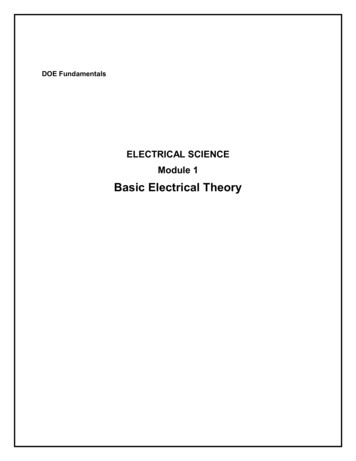
Still more math:q Cε - Cε e-tRCt RCq Cε 1- e t RCq ( t ) Q 1- e Why not justsolve this forq and I?ε-q- IR 0Cdq Cε - RCtCε - RCtε - RCtI(t) e e edt RCRCRRC is the “time constant” of the circuit; it tells us “how fast”the capacitor charges and discharges.
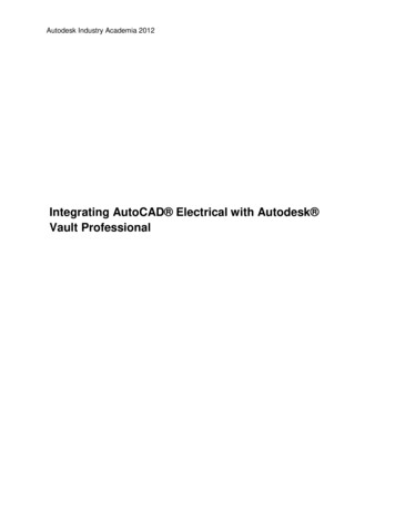
recall that this is I0,also called ImaxCharging a capacitor; summary:t RCq ( t ) Q final 1- e ε - RCtI(t) eRCharging Capacitor0.010.050.0080.040.0060.03I (A)q (C)Charging Capacitor0.0040.0020.020.010000.20.40.6t (s)0.8100.20.40.60.8t (s)Sample plots with ε 10 V, R 200 Ω, and C 1000 µF.RC 0.2 s1
In a time t RC, the capacitor charges to Q(1-e-1) or 63% of itscapacity and the current drops to Imax(e-1) or 37% of its maximum.Charging Capacitor0.010.050.0080.040.0060.03I (A)q (C)Charging Capacitor0.0040.0020.020.010000.20.40.60.81t (s)00.20.40.60.8t (s)RC 0.2 sτ RC is called the time constant of the RC circuit1
Discharging a CapacitorCapacitor charged, switchopen, no current flows.Close switch, current flows.Apply Kirchoff’s loop rule*(green loop) at the instantcharge on C is q.q- IR 0CIC q Q-q-QRswitcht 0t 0*Convention for capacitors is “like” batteries: positive if going across from - to .
Math:q- IR 0CqIR CdqI dtdq q-R dt Cdqdt qRCnegative becausecharge decreases
More math:t dtdq1 t Q q - 0 RC - RC 0 dtq1 tln ( q ) Q dt 0RCqt q ln RC Q q(t) Q e-tRCtdq Q - RCtI(t) - e I0 e RCdt RCsame equationas for charging
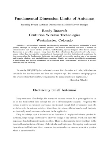
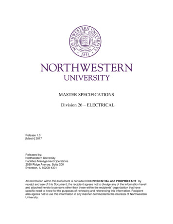
Disharging a capacitor; summary:q(t) Q0 e-tRCI ( t ) I0 etRCDischarging CapacitorDischarging Capacitor0.010.050.0080.040.0060.03I (A)q (C)-0.0040.0020.020.010000.20.40.6t (s)0.8100.20.40.60.8t (s)Sample plot
Electricity. can be described as the flow of charged particles. If the particles accumulate on an object, we term this static electricity. (D. irect . C. urrent) An electrical current that travels in one direction and used within the computer's electronic circuits. (A. lternating . C. urrent) The c