Transcription
Part VIInput/Output and InterfacingFeb. 2011Computer Architecture, Input/Output and InterfacingSlide 1
About This PresentationThis presentation is intended to support the use of the textbookComputer Architecture: From Microprocessors to Supercomputers,Oxford University Press, 2005, ISBN 0-19-515455-X. It is updatedregularly by the author as part of his teaching of the upper-divisioncourse ECE 154, Introduction to Computer Architecture, at theUniversity of California, Santa Barbara. Instructors can use theseslides freely in classroom teaching and for other educationalpurposes. Any other use is strictly prohibited. Behrooz FirstJuly 2003July 2004July 2005Mar. 2007Mar. 2008Mar. 2009Feb. 2011Feb. 2011Computer Architecture, Input/Output and InterfacingSlide 2
VI Input/Output and InterfacingEffective computer design & use requires awareness of: I/O device types, technologies, and performance Interaction of I/O with memory and CPU Automatic data collection and device actuationTopics in This PartChapter 21 Input/Output DevicesChapter 22 Input/Output ProgrammingChapter 23 Buses, Links, and InterfacingChapter 24 Context Switching and InterruptsFeb. 2011Computer Architecture, Input/Output and InterfacingSlide 3
21 Input/Output DevicesLearn about input and output devices as categorized by: Type of data presentation or recording Data rate, which influences interaction with systemTopics in This Chapter21.1 Input/Output Devices and Controllers21.2 Keyboard and Mouse21.3 Visual Display Units21.4 Hard-Copy Input/Output Devices21.5 Other Input/Output Devices21.6 Networking of Input/Output DevicesFeb. 2011Computer Architecture, Input/Output and InterfacingSlide 4
Section 21.1: IntroductionSection 21.3Section 21.4Section 21.2Feb. 2011Section 21.5: Other devicesSection 21.6: Networked I/OComputer Architecture, Input/Output and InterfacingSlide 5
21.1 Input/Output Devices and ControllersTable 3.3Some input, output, and two-way I/O devices.Input typePrime examplesOther examplesData rate (b/s)Main usesSymbolKeyboard, keypadMusic note, OCR10sUbiquitousPositionMouse, touchpadStick, wheel, glove100sUbiquitousIdentityBarcode readerBadge, fingerprint100sSales, securitySensoryTouch, motion, lightScent, brain signal100sControl, securityAudioMicrophonePhone, radio, tape1000sUbiquitousImageScanner, cameraGraphic tablet1000s-106sPhotos, publishingVideoCamcorder, DVDVCR, TV cable1000s-109sEntertainmentOutput typePrime examplesOther examplesData rate (b/s)Main usesSymbolLCD line segmentsLED, status light10sUbiquitousPositionStepper motorRobotic motion100sUbiquitousWarningBuzzer, bell, sirenFlashing lightA fewSafety, securitySensoryBraille textScent, brain stimulus100sPersonal assistanceAudioSpeaker, audiotapeVoice synthesizer1000sUbiquitousImageMonitor, printerPlotter, microfilm1000sUbiquitousVideoMonitor, TV screenFilm/video recorder1000s-109sEntertainmentTwo-way I/OPrime examplesOther examplesData rate (b/s)Main usesMass storageHard/floppy diskCD, tape, archive106sUbiquitousNetworkModem, fax, LANCable, DSL, ATM1000s-109sUbiquitousFeb. 2011Computer Architecture, Input/Output and InterfacingSlide 6
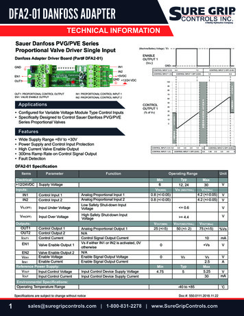
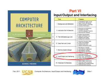
Simple Organization for Input/OutputInterruptsCPUMainmemoryCacheSystem busI/O controllerDiskFigure 21.1Feb. 2011DiskI/O controllerI/O controllerGraphicsdisplayNetworkInput/output via a single common bus.Computer Architecture, Input/Output and InterfacingSlide 7
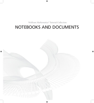
I/O Organization for Greater PerformanceCPUInterruptsMainmemoryCacheMemory busBusadapterAGPPCI busIntermediatebuses / portsGraphicsdisplayStandardBusadapterI/O busI/O controllerI/O controllerNetworkProprietaryBusadapterI/O controllerDiskDiskI/O controllerCD/DVDFigure 21.2 Input/output via intermediate and dedicated I/O buses(to be explained in Chapter 23).Feb. 2011Computer Architecture, Input/Output and InterfacingSlide 8
21.2 Keyboard and MouseFeb. 2011Computer Architecture, Input/Output and InterfacingSlide 9
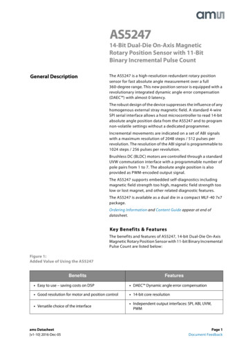
Keyboard Switches and EncodingKeycapSpringcdef89ab45670123(a) Mechanical switchwith a plungerConductor-coated membraneContacts(b) Membrane switch(c) Logical arrangement of keysFigure 21.3 Two mechanical switch designs and thelogical layout of a hex keypad.Feb. 2011Computer Architecture, Input/Output and InterfacingSlide 10
Projection Virtual KeyboardHardware:A tiny laserdevice projectsthe image of afull-sizekeyboard onany surfaceSoftware:Emulates areal keyboard,even clickingkey soundsFeb. 2011Computer Architecture, Input/Output and InterfacingSlide 11
Pointing DevicesFeb. 2011Computer Architecture, Input/Output and InterfacingSlide 12
How a Mouse Worksy rollerx rollerMouse pady axisx axisBall touching the rollersrotates them via friction(a) Mechanical mouseFigure 21.4Feb. 2011Photosensor detectscrossing of grid lines(b) Optical mouseMechanical and simple optical mice.Computer Architecture, Input/Output and InterfacingSlide 13
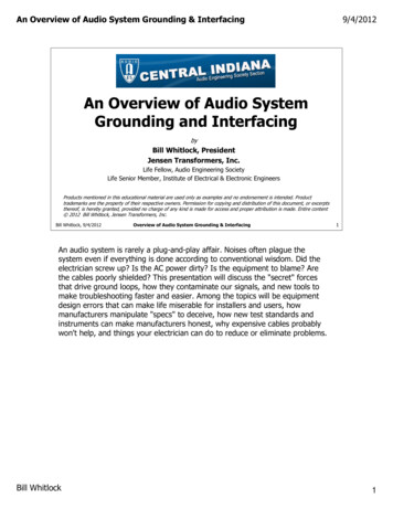
21.3Visual Display UnitsDeflection coilsElectronbeam 1KPixel info:brightness,color, etc.linesElectrongunySensitivescreen 1K pixelsFeb. 2011Frame bufferper line(a) Image formation on a CRTFigure 21.5x(b) Data defining the imageCRT display unit and image storage in frame buffer.Computer Architecture, Input/Output and InterfacingSlide 14
How Color CRT Displays WorkRGB RGB RGB RGB RGBRGBDirection ofblue beamDirection ofgreen beamDirection ofred beamShadowmaskRGBFaceplate(a) The RGB color stripesFigure 21.6Feb. 2011(b) Use of shadow maskThe RGB color scheme of modern CRT displays.Computer Architecture, Input/Output and InterfacingSlide 15
Encoding Colors in RGB FormatBesides hue, saturation is used to affect the color’s appearance(high saturation at the top, low saturation at the bottom)Feb. 2011Computer Architecture, Input/Output and InterfacingSlide 16
Flat-Panel DisplaysColumn pulsesColumn pulsesRowlinesAddresspulseColumn (data) lines(a) Passive displayFigure 21.7Feb. 2011Column (data) lines(b) Active displayPassive and active LCD displays.Computer Architecture, Input/Output and InterfacingSlide 17
Flexible Display DevicesPaper-thin tablet-sizedisplay unit by E InkSony organic light-emittingdiode (OLED) flexible displayFeb. 2011Computer Architecture, Input/Output and InterfacingSlide 18
Other Display TechnologiesFeb. 2011Computer Architecture, Input/Output and InterfacingSlide 19
21.4 Hard-Copy Input/Output DevicesDocument (face down)FiltersLensDetector:charge-coupleddevice (CCD)MirrorLight beamA/DconverterLight sourceScanningsoftwareMirrorImage fileFigure 21.8Feb. 2011Scanning mechanism for hard-copy input.Computer Architecture, Input/Output and InterfacingSlide 20
Character Formation by Dot Matricesoooooooooooooooooooooooooo oo ooo oo ooooooooooooooooooooooooo oo ooo oo ooo oo oo oo ooo oo ooo oo ooo oooo oo oooo ooooooooooooooooooooooooooo ooooo oo oo oo ooo oo ooo oo ooo oo oo ooo oo ooo oo oFigure 21.9Feb. ooooooooooooooSame dot matrix size,but with greater ooooooooooooooooForming the letter “D” via dot matrices of varying sizes.Computer Architecture, Input/Output and InterfacingSlide 21
Simulating Intensity Levels via DitheringForming five gray levels on a device that supportsonly black and white (e.g., ink-jet or laser printer)Using the dithering patterns above on each ofthree colors forms 5 5 5 125 different colorsFeb. 2011Computer Architecture, Input/Output and InterfacingSlide 22
Simple Dot-Matrix Printer MechanismFeb. 2011Computer Architecture, Input/Output and InterfacingSlide 23
Common Hard-Copy Output DevicesSheet ofpaperPapermovementPrint headmovement(a) Ink jet printingFigure 21.10Feb. 2011RotatingdrumLight fromopticalsystemRollersPrintheadInkdropletCorona wirefor chargingFusing of tonerHeaterPrint headassemblyInksupplyCleaning ofexcess tonerSheet ofpaperToner(b) Laser printingInk-jet and laser printers.Computer Architecture, Input/Output and InterfacingSlide 24
How Color Printers WorkRedGreenThe RGB scheme of color monitors is additive:various amounts of the three primary colorsare added to form a desired colorBlueAbsence of greenCyanMagentaThe CMY scheme of color printers is subtractive:various amounts of the three primary colorsare removed from white to form a desired colorYellowFeb. 2011To produce a more satisfactory shade of black,the CMYK scheme is often used (K black)Computer Architecture, Input/Output and InterfacingSlide 25
The CMYK Printing ProcessIllusion offull colorcreated withCMYK dotsFeb. 2011Computer Architecture, Input/Output and InterfacingSlide 26
Color WheelsArtist’s color wheel,used for mixing paintSubtractive color wheel,used in printing (CMYK)Additive color wheel,used for projectionPrimary colors appear at center and equally spaced around the perimeterSecondary colors are midway between primary colorsTertiary colors are between primary and secondary colorsSource of this and several other slides on color: ee also color theory tutorial: Color%20Theory.pdf)Feb. 2011Computer Architecture, Input/Output and InterfacingSlide 27
21.5 Other Input/Output DevicesFeb. 2011Computer Architecture, Input/Output and InterfacingSlide 28
Sensors and ActuatorsCollecting info about the environment and other conditions Light sensors (photocells) Temperature sensors (contact and noncontact types) Pressure sensorsSSNSNSSSNNSNNSNNSSNN(a) Initial state(a) AfterrotationFigure 21.11Stepper motor principlesof operation.Feb. 2011Computer Architecture, Input/Output and InterfacingSlide 29
Converting Circular Motion to Linear MotionLocomotiveFeb. 2011ScrewComputer Architecture, Input/Output and InterfacingSlide 30
21.6 Networking of Input/Output DevicesComputer 1Printer 2CameraEthernetComputer 3Printer 1Computer 2Printer 3Figure 21.12 With network-enabled peripherals,I/O is done via file transfers.Feb. 2011Computer Architecture, Input/Output and InterfacingSlide 31
Input/Output in Control and Embedded SystemsCPU andmemoryNetworkinterfaceIntelligent devices,other computers,archival storage, .DigitaloutputinterfaceSignalconversionDigital actuators:stepper motors,relays, alarms, .D/AoutputinterfaceSignalconversionAnalog actuators:valves, pumps,speed regulators, ital sensors:detectors, counters,on/off switches, .A/D inputinterfaceAnalogsignalconditioningAnalog sensors:thermocouples,pressure sensors, .Figure 21.13 The structure of a closed-loopcomputer-based control system.Feb. 2011Computer Architecture, Input/Output and InterfacingSlide 32
22 Input/Output ProgrammingLike everything else, I/O is controlled by machine instructions I/O addressing (memory-mapped) and performance Scheduled vs demand-based I/O: polling vs interruptsTopics in This Chapter22.1 I/O Performance and Benchmarks22.2 Input/Output Addressing22.3 Scheduled I/O: Polling22.4 Demand-Based I/O: Interrupts22.5 I/O Data Transfer and DMA22.6 Improving I/O PerformanceFeb. 2011Computer Architecture, Input/Output and InterfacingSlide 33
22.1 I/O Performance and BenchmarksExample 22.1: The I/O wallAn industrial control application spent 90% of its time on CPUoperations when it was originally developed in the early 1980s.Since then, the CPU component has been upgraded every 5 years,but the I/O components have remained the same. Assuming thatCPU performance improved tenfold with each upgrade, derive thefraction of time spent on I/O over the life of the system.SolutionApply Amdahl’s law with 90% of the task speeded up by factors of10, 100, 1000, and 10000 over a 20-year period. In the course ofthese upgrades the running time has been reduced from the original1 to 0.1 0.9/10 0.19, 0.109, 0.1009, and 0.10009, making thefraction of time spent on input/output 52.6, 91.7, 99.1, and 99.9%,respectively. The last couple of CPU upgrades did not really help.Feb. 2011Computer Architecture, Input/Output and InterfacingSlide 34
Types of Input/Output BenchmarkSupercomputer I/O benchmarksReading large volumes of input dataWriting many snapshots for checkpointingSaving a relatively small set of resultsI/O data throughput, in MB/s, is importantTransaction processing I/O benchmarksHuge database, but each transaction fairly smallA handful (2-10) of disk accesses per transactionI/O rate (disk accesses per second) is importantFile system I/O benchmarksFile creation, directory management, indexing, . . .Benchmarks are usually domain-specificFeb. 2011Computer Architecture, Input/Output and InterfacingSlide 35
22.2Memory location(hex address)0xffff000031Input/Output AddressingInterrupt enableIER76543210Data byte0xffff0004Device readyKeyboard controlKeyboard data32-bit device registers0xffff0008310xffff000cIER76543210Data byteDisplay controlDisplay dataFigure 22.1 Control and data registers for keyboardand display unit in MiniMIPS.Feb. 2011Computer Architecture, Input/Output and InterfacingSlide 36
Hardware for I/O AddressingControlAddressDataMemorybusDevice statusDeviceaddressDevice dataCompare Figure 22.2Feb. 2011ControllogicDevicecontrollerAddressing logic for an I/O device controller.Computer Architecture, Input/Output and InterfacingSlide 37
Data Input from KeyboardExample 22.2Write a sequence of MiniMIPS assembly language instructions tomake the program wait until the keyboard has a symbol to transmitMemory locationInterrupt enableand then read the symbol into register v0.(hex address)0xffff000031Solution0xffff0004Device readIER76543210KeyboardData byteKeyboard32-bit device registersThe program must continually examine the keyboard control register,I0xffff0008Display coER3176543210ending its “busy wait” when the R bit has been asserted.0xffff000cluiidle: lwandibeqlw t0,0xffff t1,0( t0) t1, t1,0x0001 t1, zero,idle v0,4( t0)#####Data byteput 0xffff0000 in t0get keyboard’s control wordisolate the LSB (R bit)if not ready (R 0), waitretrieve data from keyboardThis type of input is appropriate only if the computer is waiting for acritical input and cannot continue in the absence of such input.Feb. 2011Computer Architecture, Input/Output and InterfacingSlide 38Display da
Data Output to Display UnitExample 22.3Memory locationInterrupt enableDevice re(hex address)Write a sequence of MiniMIPS assemblylanguage instructions to EI R0xffff0000316543210make the program wait until the display0xffff0004unit is readyto accept a 7Datanewbytesymbol and then write the symbol from a0 to the displayunit.32-bit deviceregisters0xffff000831Solution0xffff000c t0,0xffff t1,8( t0) t1, t1,0x0001 t1, zero,idle a0,12( t0)#####DisplayData byteDisplayput 0xffff0000 in t0get display’s control wordisolate the LSB (R bit)if not ready (R 0), waitsupply data to display unitThis type of output is appropriate only if we can afford to have theCPU dedicated to data transmission to the display unit.Feb. 2011Computer Architecture, Input/Output and InterfacingKeyboaIER76543210The program must continually examine the display unit’s controlregister, ending its “busy wait” when the R bit has been asserted.luiidle: lwandibeqswKeyboaSlide 39
22.3Scheduled I/O: PollingExamples 22.4, 22.5, 22.6What fraction of a 1 GHz CPU’s time is spent polling the followingdevices if each polling action takes 800 clock cycles?Keyboard must be interrogated at least 10 times per secondFloppy sends data 4 bytes at a time at a rate of 50 KB/sHard drive sends data 4 bytes at a time at a rate of 3 MB/sSolutionFor keyboard, divide the number of cycles needed for 10interrogations by the total number of cycles available in 1 second:(10 800)/109 0.001%The floppy disk must be interrogated 50K/4 12.5K times per sec(12.5K 800)/109 1%The hard disk must be interrogated 3M/4 750K times per sec(750K 800)/109 60%Feb. 2011Computer Architecture, Input/Output and InterfacingSlide 40
22.4Demand-Based I/O: InterruptsExample 22.7Consider the disk in Example 22.6 (transferring 4 B chunks of data at3 MB/s when active). Assume that the disk is active 5% of the time.The overhead of interrupting the CPU and performing the transfer is1200 clock cycles. What fraction of a 1 GHz CPU’s time is spentattending to the hard disk drive?SolutionWhen active, the hard disk produces 750K interrupts per second0.05 (750K 1200)/109 4.5% (compare with 60% for polling)Note that even though the overhead of interrupting the CPU is higherthan that of polling, because the disk is usually idle, demand-basedI/O leads to better performance.Feb. 2011Computer Architecture, Input/Output and InterfacingSlide 41
Interrupt HandlingUpon detecting an interrupt signal, provided the particularinterrupt or interrupt class is not masked, the CPU acknowledgesthe interrupt (so that the device can deassert its request signal)and begins executing an interrupt service routine.1. Save the CPU state and call the interrupt service routine.2. Disable all interrupts.3. Save minimal information about the interrupt on the stack.4. Enable interrupts (or at least higher priority ones).5. Identify cause of interrupt and attend to the underlying request.6. Restore CPU state to what existed before the last interrupt.7. Return from interrupt service routine.The capability to handle nested interrupts is important in dealing withmultiple high-speed I/O devices.Feb. 2011Computer Architecture, Input/Output and InterfacingSlide 42
22.5I/O Data Transfer and DMAOther cont rolReadWrite’DataReady’SystembusAddressDataBus requestCPUandcacheDMAcontrollerBus grantStatus SourceLength Dest’nMainmemoryTypicalI/OdeviceFigure 22.3 DMA controller shares the systemor memory bus with the CPU.Feb. 2011Computer Architecture, Input/Output and InterfacingSlide 43
DMA OperationCPUBusRequestBusGrantDMA(a) DMA trans fer in one continuous burstCPUBusRequestBusGrantDMA(b) DMA trans fer in several shorter burstsFigure 22.4 DMA operation and the associatedtransfers of bus control.Feb. 2011Computer Architecture, Input/Output and InterfacingSlide 44
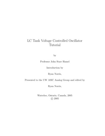
22.6Improving I/O PerformanceExample 22.9: Effective I/O bandwidth from diskConsider a hard disk drive with 512 B sectors, average access latencyof 10 ms, and peak throughput of 10 MB/s. Plot the variation of theeffective I/O bandwidth as the unit of data transfer (block) varies insize from 1 sector (0.5 KB) to 1024 sectors (500 KB).SolutionThroughput (MB / s)10Figure 22.5Feb. 2011865 MB/s420.05 MB/s00100200300Block size (KB)Computer Architecture, Input/Output and Interfacing400500Slide 45
Computing the Effective ThroughputElaboration on Example 22.9: Effective I/O bandwidth from diskTotal access time for x bytes 10 ms xfer time (0.01 10–7x) sEffective access time per byte (0.01 10–7x)/x s/BEffective transfer rate x/(0.01 10–7x) B/sFor x 100 KB: Effective transfer rate 105/(0.01 10–2) 5 106 B/sAverageaccesslatency 10 msPeakthroughput 10 MB/sThroughput (MB / s)10Figure 22.5Feb. 2011865 MB/s420.05 MB/s00100200300Block size (KB)Computer Architecture, Input/Output and Interfacing400500Slide 46
Distributed Input/OutputCPUCPUCPUCPUMemHCAMemHCAHCA HostchanneladapterSwitchModule withbuilt-in switchRouterSwitchSwitchHCAI/OFigure 22.6Feb. 2011HCAI/OHCAI/OHCAHCATo other subnetsI/OI/OExample configuration for the Infiniband distributed I/O.Computer Architecture, Input/Output and InterfacingSlide 47
23 Buses, Links, and InterfacingShared links or buses are common in modern computers: Fewer wires and pins, greater flexibility & expandability Require dealing with arbitration and synchronizationTopics in This Chapter23.1 Intra- and Intersystem Links23.2 Buses and Their Appeal23.3 Bus Communication Protocols23.4 Bus Arbitration and Performance23.5 Basics of Interfacing23.6 Interfacing StandardsFeb. 2011Computer Architecture, Input/Output and InterfacingSlide 48
23.1Trench with viaIntra- and Intersystem LinksMetal layer 4Trench1. Etched and insulatedMetallayer 32. Coated with copperviaviaMetallayer 2Contact3. Excess copper removed(a) Cross section of layersMetal layer 1(b) 3D view of wires on multiple metal layersFigure 23.1 Multiple metal layers provide intrasystem connectivityon microchips or printed-circuit boards.Feb. 2011Computer Architecture, Input/Output and InterfacingSlide 49
Multiple Metal Layers on a Chip or PC BoardCross section of metal layersActive elements andtheir connectorsModern chips have8-9 metal layersUpper layers carrylonger wires aswell as those thatneed more powerFeb. 2011Computer Architecture, Input/Output and InterfacingSlide 50
Intersystem LinksComputer(a) RS-232(b) EthernetFigure 23.2Example intersystem connectivity schemes.DTR: data terminalreadySignalground5CTS: clearto sendFeb. 2011Transmitdata49Figure 23.3(c) ATM3827Receivedata16RTS: requestto sendDSR: data setreadyRS-232 serial interface 9-pin connector.Computer Architecture, Input/Output and InterfacingSlide 51
Intersystem Communication alfiberFigure 23.4 Commonly used communication mediafor intersystem connections.Feb. 2011Computer Architecture, Input/Output and InterfacingSlide 52
Comparing Intersystem LinksTable 23.1Summary of three interconnection schemes.Interconnection propertiesRS-232EthernetATMMaximum segment length (m)10s100s1000sMaximum network span (m)10s100sUnlimitedUp to 0.0210/100/1000155-25001100s53 110s-100s100sInput/OutputLANBackboneLowLowHighBit rate (Mb/s)Unit of transmission (B)Typical end-to-end latency (ms)Typical application domainTransceiver complexity or costFeb. 2011Computer Architecture, Input/Output and InterfacingSlide 53
23.2Buses and Their Appeal101203n–1n–223n–1n–2Point-to-point connections between n units require n(n – 1) channels,or n(n – 1)/2 bidirectional links; that is, O(n2) linksBus connectivity requires only one input and one output port per unit,or O(n) links in allFeb. 2011Computer Architecture, Input/Output and InterfacingSlide 54
Bus Components and Types.Control.Address.DataFigure 23.5Handshaking,direction,transfer mode,arbitration, .one bit (serial)to several bytes;may be sharedThe three sets of lines found in a bus.A typical computer may use a dozen or so different buses:1. Legacy Buses: PC bus, ISA, RS-232, parallel port2. Standard buses: PCI, SCSI, USB, Ethernet3. Proprietary buses: for specific devices and max performanceFeb. 2011Computer Architecture, Input/Output and InterfacingSlide 55
23.3Bus Communication ProtocolscdefghClockAddress placed on the busAddressDataWaitFigure 23.6WaitDataavailabilityensuredSynchronous bus with fixed-latency devices.RequestAddressor dataWaitdcdehfAckfghiReadyFigure 23.7 Handshaking on an asynchronous bus for aninput operation (e.g., reading from memory).Feb. 2011Computer Architecture, Input/Output and InterfacingSlide 56
Example Bus OperationcdefghijkCLKFRAME′C/BE′ADI/O readByte enableAddressData 0Data 1Data 2IRDY′Data 3WaitTRDY′WaitDEVSEL′Transfer Address AD turn- Datainitiation transfer around transferFigure 23.8Feb. transferI/O read operation via PCI bus.Computer Architecture, Input/Output and InterfacingSlide 57
23.4R0R1R2Bus Arbitration and Performance.Sync.ArbiterR n 1.G0G1G2Gn 1Bus releaseFigure 23.9Feb. 2011General structure of a centralized bus arbiter.Computer Architecture, Input/Output and InterfacingSlide 58
Some Simple Bus ArbitersRound iRn–1G0GiGn–1Starvation avoidanceRotating priorityWith fixed priorities, low-priorityunits may never get to use thebus (they could “starve”)Idea: Order the units circularly,rather than linearly, and allow thehighest-priority status to rotateamong the units (combine a ringcounter with a priority circuit)Combining priority with serviceguarantee is desirableFeb. 2011Computer Architecture, Input/Output and InterfacingSlide 59
Daisy ChainingR0R1R2.Sync.Bus releaseArbiter.BusgrantG0G1G2DeviceADaisy chain of devicesDeviceBDeviceCDeviceDBus requestFigure 23.9 Daisy chaining allows a small centralized arbiter toservice a large number of devices that use a shared resource.Feb. 2011Computer Architecture, Input/Output and InterfacingSlide 60
23.5NWContactpointBasics of InterfacingGround 5 V DCSMicrocontrollerwith internalA/D converterEPin x of port yFigure 23.11 Wind vane supplying an output voltage inthe range 0-5 V depending on wind direction.Feb. 2011Computer Architecture, Input/Output and InterfacingSlide 61
23.6Table 23.2Attributes Interfacing StandardsSummary of four standard interface buses.Name PCISCSIFireWireUSBType of busBackplaneParallel I/OSerial I/OSerial I/OStandard designationPCIANSI X3.131IEEE 1394USB 2.0Typical application domainSystemFast I/OFast I/OLow-cost I/OBus width (data bits)32-648-3221Peak bandwidth (MB/s)133-5125-4012.5-500.2-15Maximum number of devices1024*7-31#63127 Maximum span (m) 13-254.5-72 5-30 Arbitration methodCentralizedSelf-selectDistributedDaisy chainTransceiver complexity or costHighMediumMediumLowNotes:Feb. 2011* 32 per bus segment;# One less than bus width; With hubs (repeaters)Computer Architecture, Input/Output and InterfacingSlide 62
Standard ConnectorsUSB AHost side432114Max cablelength: 5mHost(controller & hub)USB BDevice side23HubHubPin 1: 5V DCPin 4: GroundFigure 23.12Pin 2: Data Pin 3: Data DeviceHubDeviceDeviceDeviceSingle productwith hub & deviceUSB connectors and connectivity structure .Pin 1: 8-40V DC, 1.5 APin 2: GroundPin 3: Twisted pair B Pin 4: Twisted pair B Pin 5: Twisted pair A Pin 6: Twisted pair A Shell: Outer shieldFigure 23.13 IEEE 1394 (FireWire) connector.The same connector is used at both ends.Feb. 2011Computer Architecture, Input/Output and InterfacingSlide 63
24 Context Switching and InterruptsOS initiates I/O transfers and awaits notification via interrupts When an interrupt is detected, the CPU switches context Context switch can also be used between users/threadsTopics in This Chapter24.1 System Calls for I/O24.2 Interrupts, Exceptions, and Traps24.3 Simple Interrupt Handling24.4 Nested Interrupts24.5 Types of Context Switching24.6 Threads and MultithreadingFeb. 2011Computer Architecture, Input/Output and InterfacingSlide 64
24.1System Calls for I/OWhy the user must be isolated from details of I/O operationsProtection: User must be barred from accessing some disk areasConvenience: No need to learn details of each device’s operationEfficiency: Most users incapable of finding the best I/O schemeI/O abstraction: grouping of I/O devices into a small number ofgeneric types so as to make the I/O device-independentCharacter stream I/O: get( ), put( ) – e.g., keyboard, printerBlock I/O: seek( ), read( ), write( ) – e.g., diskNetwork Sockets: create socket, connect, send/receive packetClocks or timers: set up timer (get notified via an interrupt)Feb. 2011Computer Architecture, Input/Output and InterfacingSlide 65
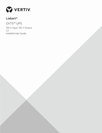
24.2Interrupts, Exceptions, and TrapsInterruptExceptionTrapBoth general term for any diversion and the I/O typeCaused by an illegal operation (often unpredictable)AKA “software interrupt” (preplanned and not rare)Studying Parhami’sbook for test6:557:40 8:019:46Stomach sendsinterrupt signalE- mailarrivesEating dinnerReading/sending e-mail8:42Telemarketercalls8:539:20Best friendcallsTalk ing on the phoneFigure 24.1Feb. 2011The notions of interrupts and nested interrupts.Computer Architecture, Input/Output and InterfacingSlide 66
24.3Simple Interrupt HandlingAcknowledge the interrupt by asserting the IntAck signalNotify the CPU’s next-address logic that an interrupt is pendingSet the interrupt mask so that no new interrupt is IntAlertSignalsfrom/toCPUIntEnableFigure 24.2Feb. 2011Simple interrupt logic for the single-cycle MicroMIPS.Computer Architecture, Input/Output and InterfacingSlide 67
Interrupt TimingcdefghClockIntReqSynchronized versionIntAckIntMaskIntAlertFigure 24.3Feb. 2011Timing of interrupt request and acknowledge signals.Computer Architecture, Input/Output and InterfacingSlide 68
Next-Address Logic with Interrupts 0/30/30(PC) 31:28 jta(rs) 31:2SysCallAddrIntHandlerAddrPCSrcFigure 24.4 Part of the next-address logic for single-cycleMicroMIPS, with an interrupt capability added (compare withthe lower left part of Figure 13.4).Feb. 2011Computer Architecture, Input/Output and InterfacingSlide 69
24.4Nested InterruptsprogPCinst(a)inst(b)Interrupts disabledand (PC) savedIntdetectedint1InterrupthandlerSave stateSave int infoEnable int’sPCinst(c)inst(d)In tdetectedint2Save stateSave int infoInterrupts disabled Enable int’sand (PC) savedRestore stateReturnFigure 24.6Feb. 2011InterrupthandlerRestore stateReturnExample of nested interrupts.Computer Architecture, Input/Output and InterfacingSlide 70
24.5Scanning e-mailmessagesTypes of Context SwitchingTaking notesTask 1Task 2Task 3TimesliceContextswitchTalking on telephone(a) Human multitaskingFigure 24.7Feb. 2011(b) Computer multitaskingMultitasking in humans and computers.Computer Architecture, Input/Output and InterfacingSlide 71
24.6Threads and MultithreadingThread 1Thread 2Thread 3Spawn additional threadsSyncSync(a) Task graph of a programFigure 24.8Feb. 2011(b) Thread structure of a taskA program divided into tasks (subcomputations) or threads.Computer Architecture, Input/Output and InterfacingSlide 72
Multit
Feb. 2011 Computer Architecture, Input/Output and Interfacing Slide 7 Simple Organization for Input/Output Figure 21.1 Input/output via a single common bus. CPU Cache Main memory I/O controller I/O controller I/O controller