Transcription
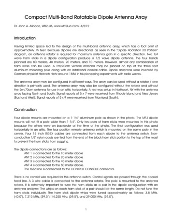
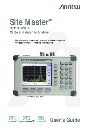
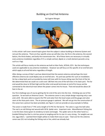
Building an End Fed AntennaBy Eugene MorganIn this article I will cover several topics given that the subject is about building an Antenna System andnot just the antenna. There are four specific areas we will dive into, the first is the antenna, the secondbaluns, the third chokes, and lastly the transmission line. All of these items are necessary in virtuallyevery antenna installation regardless if it’s a simple vertical, dipole or a multi element parasitic arraysuch as a Yagi.This article will focus mainly on the antenna we built at Alan Parks, N7SHA, QTH. But the techniquesused are applicable to any antenna installation. However we will focus on the specific of an end fed wirewhich apply to all end fed wires regardless of length.After doing a survey of Alan’s yard we determined that the easiest antenna and perhaps the mosteffective antenna we could deploy was an end fed wire. His yard was perfect for such an installation.He has a deep back yard surrounded by many tall trees with his house sitting near the front of the lot.We determined that we could run a wire over 180 feet into one of the tall trees in his back yard. The farend would be close to 50 feet high and the other end would terminate at end of his house and beconnected to the electrical mast where the power comes into his house. That end would be about 20feet in the air.Our first challenge was of course getting the far end of the wire into the tree. Climbing was out of thequestion. So we built an Antenna Canon. The antenna canon is very simple design requiring only a sawand a drill. We were able to acquire the PVC and valve from the local Lowes and the gauge and valvestem at the Auto parts store. The air pressure gauge is optional. We will not go into the construction ofthe canon but a picture has been provided, see Figure 1 and can provide an easy example to follow.The canon is made from 2” PVC and a length of ¾ PVC for the barrel. The valve is a gas line ball valve.The reel is an old fishing reel wound with 50 lb. Spider wire. Important note: Monofilament fishing lineis not the best choice given its tendency to twist and tangle. The spider wire on the other hand is abraided fishing line that is a lot less prone to tangling and for its size it is very strong. For weights we use2oz. egg sinkers. I painted them bright yellow to make them easy to spot. Total cost for the antennacanon was 31 not including the fishing real or line, which we already had.
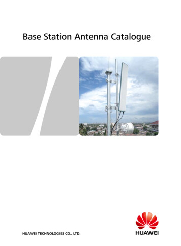
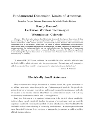
Although it took us several tries we were able to get the line where we wanted it. After placing the linewe pulled up progressive stronger line until we had a final haul line in place which was a 50’ length ofmountain climbing rope.The key consideration is the abrasion the haul line will take. Climbing rope is a good choice given it’sresistance to abrasion, its ability to stretch, and its larger diameter. We understand that not everyonehas a bit of old climbing rope laying around. The key thing is to use as large a line as possible, not somuch for its strength but for its resistance to wear. If climbing the tree is an option then inserting thehaul line through a small bit of garden hose can be employed to minimize wear on both the haul ropeand the tree. This is the technique we used at N7KID’s installation. To the haul line we tied a smallcarabiner that we used to run our halyard through. This made it possible to lower or adjust the antennawithout disturbing the haul line. We will readjust the haul line from time to time in order to move thewear spot. By using the halyard we can readjust the antenna as needed without putting any stress onthe tree. See Figure 2 for details of how we rigged the haul line and antenna halyard.Figure 1: The Air Powered Antenna Canon
Figure 2: Line configurationNow that the antenna is in the tree and the other end is tied off to the house it’s now time to focus onconnecting the antenna to radio.How Long Should My Wire be?We started off the article with how to install an end fed wire but we kind of skipped over figuring outhow long a wire to put up. The table below should help to fill in that gap. It presents a number ofoptions. I have personally built three of these antenna. The first was Alans (N7SHA) which we didn’tmeasure but I suspect it would be in the 173’ range. The second, was Bruce’s, (N7KID) which wecarefully cut to 85’ with over 65’ of feed line and finally my antenna at 203’ feet, however my feedline isonly 90’ long. I took careful measurement of my antenna and here are the SWR @ Radio5.2:13.3:11.5:11.3:11.4:11.7:12.2:1Table 1:SWR Results with 203' wire with 90' feedlineThe SWR was fairly close to predictions with the exception of 160 meters. Here the SWR was higherthan expected, but still within range of the tuner in my Yaesu FT-950. I suspect the reason for the higherthan expected SWR was a less than optimum feedline length, the recommended length is 130’.
Fortunately the line loss on 160 meters with a 5.1: SWR across 90’ of RG8 (.6dB loss at 10mhz per 100’)is calculated to be only .28dB. Remember that 6 dB 1 S unit on a properly calibrated S meter. So theloss will be virtually undetectable. The loss on 10 meters will be a bit higher at 1.14dB, which is stillBands Covered (meters)Wire Length (feet)Minimum Coax Length (feet)40-30-20-1535-43, 49-63, 70-853540-30-20-1735-45, 54-64, 67-773580-40-30-20-17-15-12-1038-44, 55, 60, 68-735080-60-40-30-20-17-15-12-1055, 68-73, 85, 92, 102, 120-12565160-80-40-30-20-17-15-12-10135, 141, 173, 203130undetectable on the normal S meter.Table 2: Optimum wire and feedline lengthsSWR for all lengths should typically be under 2.2:1 and in most cases will be under 1.8:1 for 160-10mwhich will allow most built in ATU’s to match the antenna on all bands. Initial installation should utilize alength longer than the recommended length shown. Experimenting by slightly changing the wire length( or -) is encouraged to provide best overall performance for individual installations. If you can get thelength close enough that your tuner can establish a conjugate match on each target band should begood enough. Remember that one S unit on your S meter is equal to 6 dB. At HF the differencebetween a 2:1 and a 3:1 SWR is virtually undetectable.As you can see from the above dimensions you don’t need a massive lot or a small farm to erect an endfed wire antenna. One can install an end fed wire in an attic or even on a small urban lot. Also, an endfed wire is a much simple antenna especially when compared to something like a G5RV which requiresthe use of twin lead, which can extremely problematic in an attic space and highly susceptible to RFI. Ithink the end fed wire has gotten a bad rap because they are usually not properly installed with thenecessary unun and choke.How to Feed an End Fed Wire? The Balun or in this case the UnunThe end fed wire regardless of its length presents a high impedance to the feedline. If the intention is tobuild a ½ wave mono band antenna then it is necessary to attach a 48:1 unun at the feed point given theextremely high impedance. But if it’s a multi band antenna and is not ½ wavelength long on any of theintended bands then a 9:1 unun is necessary.Why an Unun? Typically we find two kinds of impedance transformers, balanced and unbalanced.Given that today nearly all antennas used by the ham community are fed with 50 ohm coaxial cable. Inaddition a balun is often used to connect then unbalanced coaxial cable to a semi balanced antenna.You will note that throughout I use the term (semi) balanced antenna. The reason for this is that inreality the only really balance antenna is one that exists in free space. Antenna unbalance is caused by
all those things that surround an antenna, buildings, trees, powerlines, fences, cars, and so on. In theoryantennas, like dipoles and Yagi’s, are consider balanced antennas, unless they are up high and in theclear there will be some level of unbalance in the antenna. As you will see in the next paragraph theseimbalances can cause problems that in some cases is very noticeable and in other instances can be verysubtle.Coaxial cable is considered an unbalanced feed system. So if you attach an unbalance feed line to a(semi) balance antenna such as a dipole or Yagi you will get unpredictable and often unreliable andmore importantly undesirable results, that are caused by common mode currents. Common modecurrents on the feed line can manifest themselves in a variety of really icky ways. In worst casescenarios they can invade your shack and cause all sorts of issues with RF noise, electrical shocks, andcomputer mice and wireless routers that behave erratically. A much harder condition to detect is whenthe coaxial cable is acting like an antenna on both transmit and receive! On transmit the radiationpattern may be off, the SWR unnecessarily higher than it should be and worst of all, some of thatprecious RF power is being radiated where it shouldn’t be radiated. During the receive mode theantenna may be picking up random electrical noise and RFI. In short common mode currents are bad.We will go more into common mode currents when we get into RF chokes later in this article.In the case of the end fed antenna it is an unbalance antenna so it is possible to connect you unbalancecoaxial cable to an unbalance antenna but now you have another issue, an impedance mismatch. Theend fed wire has a high impedance, usually several hundred ohms, while the coaxial feedline has a muchlower 50 ohm impedance. So that won’t work either! So what do we do?In the case of the end fed wire we need to use an unbalanced impedance transformer, or in other wordsa 9:1 Unun (unbalanced to unbalanced). It will convert the 50 ohm impedance of our coax to a 450 ohmimpedance and allow us to connect the unbalanced feedline to our unbalanced 450 ohm antenna. Thatshould help to tame the antenna mismatch to a degree that most inboard ATU’s can establish aconjugate match.In the case of the end fed wire we know what we need to do, either buy a 9:1 unun or build one. Thereare several good options on the market today. LDG sells one that is good for a 100 watt station foraround 30. If you’re running a bit more power then Palomar Engineering or Balun Designs both havegood solutions, some a bit on the pricy side. Our other option is to build our own. Now don’t stopreading at this point. These things are not hard to build, you can get everything you need from Amazonand Lowes. And they are not expensive. As to tools all one needs is a drill and a couple of right size bits.And there is a goodly number of YouTube videos that will walk you through the process. I think thefollowing YouTube videos is one of the better ones: https://www.youtube.com/watch?v VAV9Wws-Bs0In his video he used a different core. My research suggests that Ferrite (FT) is better material forbuilding ununs and baluns. Now that you have watched a video or two let me tell you what you willneed acquire:From Amazon:1. If you running less than about 500 watts you will need one FT240-43 core. They run about 12.If you are running more power you will need two. The type 43 mix works best in the HF range.If you are building for UHF of VHF a different mix is necessary.
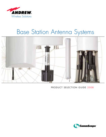
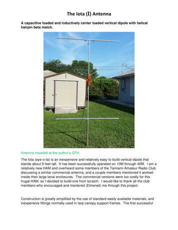
2. You will need a roll of 14 AWG enamel magnet wire. The Amazon descriptions is: “TEMCo 14AWG Copper Magnet Wire - 8 oz 40 ft 200 C Magnetic Coil Winding” It runs about 20 for 40feet. This will be more wire than you will ever need and it gives you some extra in case you flubit up. Don’t worry this is not brain surgery. However, if you have actually read this article thisfar and are really serious about building your own unun come see me. I have part of a 40’ rolland I will gladly share.3. You will need a little more than 7’ of Teflon tubing. The Amazon description is: “PTFE Teflontubing 5ft - 2mm ID X 3mm OD - Allen Tech PTFE Teflon Tube” It runs 7 per 5 ft. You will needto buy two packages. You will insert the enamel wire into this tubing. This will give you a littlemore power handling capabilities and ensure the wire does not short out on the core.4. You will need one SO-239. They come in quantities of 5 and will cost you a little over a buck apiece.From Lowes:1. You will need one electrical box. Home Depot didn’t have the right kind, Lowes did. Look forthe square grey 4”X4” plastic box in the electrical department.2. You will need two 6x32x3/4 stainless steel screws with stainless steel nylock nuts. These are forsecuring the SO-239 to the housing.3. You will need three small eyebolts with nuts and washers. Use all stainless steel. In mine I useda fender washer rather than a normal sized washer. The fender washers are larger than thenormal washers and will help to spread the strain put on the eye bolts over a larger area of thebox. One on each side for the antenna wire, one for an optional ground, and one to support theantenna and unun.These devices are really simple to build. And if you’re not sure, call me, I’ll be glad to give you a hand.Figure 3 is a picture of the one I built. It’s modeled after the Balun Designs 9:1 unun. See Figure 4 for adiagram of the circuit. I used color electrical tape to keep track of each wire. I will admit after you dothe winding and are looking at 6 wires you may find it intimidating. Just go slow and double check yourconnections before you break out the soldering iron. No one’s going to take away your birthday if youget it wrong. And if you mess it up, you did buy 40’ of wire so you can start all over if you want.When I tested the unun I put a 450 ohm load across the antenna attachment eyes and connected anantenna analyzer to the SO-239. I got a 1:1 reading up to 4 Mhz and a 1.1:1 reading up to 20 Mhz. Ididn’t test it higher. This version should be able to comfortably handle up to 600 watts. The antennawire is attached to the right side and the left side can be attached to ground. You will note that in myunun I did not include the suspension eye bolt that normally would be mounted to the top of the box.Rather than hanging mine, I mounted mine to a 4X4 7’ fence post.
Figure 3: A 600 watt homebrew 9:1 UnunFigure 4: 9:1 Unun Circuit DesignNow that we have built our 9:1 Unun and attached it to our antenna wire it’s now time to move on toour Common Mode Choke.The Common Mode Current ChokeVirtually every antenna will benefit from an RF Choke. That unfortunately is not well understood bymost hams. The purpose of the choke is to minimize the common mode currents (CMC) that are caused
by a number of things, an unbalance in the antenna and or a high SWR. And the sad truth is that mosthams don’t know they have a problem with CMC. In the case of Alan’s installation when we added thechoke we saw a significant drop in the noise level on 80-20 meters. And we saw a drop in the 15-10meter bad as well but it was not as significant. Given the design of our choke that was not surprising.Our choke was designed specifically for the 80-20 meter band. Before we get into the design of a chokelet’s first understand what they are for and what they do.Common mode currents: The primary purpose of a choke is to impede current from flowing on theoutside of the feed line. Understand we are talking exclusively about coaxial cable. In a perfect systemwhat happens is the RF energy runs up and down the coaxial cable on the inside of the cable and all theenergy is converted into RF and goes out the antenna. But as we all know in the real world there is noperfect system.The reality of a typical antenna installation the halves of an antenna are rarely balanced due to thedistorting effects of the antennas and there is almost always some mismatch between the feedline andthe antenna. As a result, practical antennas can be very susceptible to the way they are installed and arerarely well-balanced. By being unbalanced the currents on both halves will be different.In contrast with the messy environment the antenna is placed the story is different inside a coax cable.Without getting too technical the currents flowing on the center conductor and the inside of the shieldare equal and 180 out of phase. The two center conductor and the inside shield of the coax are closelycoupled along the entire length of the transmission line. So the equal and opposite relationship isstrongly enforced. What is going on inside the cable is unaffected by what is going on outside of thecable. The skin effect causes HF currents to flow only close to the surfaces of the conductors. The innerand outer surfaces of the coaxial shield behave as two entirely independent conductors. The cable maybe taped to a tower or even buried while the currents and voltages inside the cable remain exactly thesame.The problem arises when connecting a coaxial cable to an antenna. If the antenna is in any wayunbalanced, which is almost always the case, a difference will appear between the currents flowing onone side of the antenna versus the other side of the antenna. Remember, in most cases one side of theantenna is connected to the center conductor and the other side of the antenna to the shield. It is theunbalance between these two halves of the antenna that flow on the outside of the shield, these are thecommon mode currents.This imbalance which results in different amounts of current flowing in each half of the antenna willcause the coax to radiate by itself. This radiation would be mainly vertically polarized since mosttransmission lines predominantly run vertically. Here’s the really icky part, the feedline radiation causesdistortion of the radiation pattern, RF current on metal masts and Yagi booms plus problems with strayRF in the shack. Even worse, the RF currents may flow in the mains and on TV cables leading to all sortsof electromagnetic problems.The side of the antenna which is connected to the coax shield and the outer coax shield form a secondantenna that will also produce an impedance. This impedance, seen looking down the outside surface ofthe coax outer shield to ground, is called the common mode impedance.
The common mode impedance will depend on a number of factors: the coax length and the path fromthe transmitter chassis to the RF ground. The path from the transmitter chassis to ground may gothrough the station grounding bus, the transmitter power cord, the house wiring and even the powerline’s service ground. In other words, the overall length of the coaxial outer surface and the other partsmaking up the ground can actually be quite different from what you might expect or want.In a worst case, common mode impedance will occur when the effective path to ground is an oddmultiple length of λ/2, making this path a half-wavelength resonant. In this case, we have a sort oftransmission line transformer that practically short circuits the antenna arm that is connected to thecoax shield and resulting in a very low impedance at the antenna feed point.Another extreme situation that might occur is when the overall effective length of the coaxial feedline toground is an odd multiple length of λ/4. The common mode impedance transformed to the feed point isthen high in comparison to the dipole’s natural feed point impedance.In short what this means is that when we see a varying SWR measurement with varying coax cablelength the inference is there is an unbalance in the antenna and there is common mode current flowingon the outside shield.So now we know what CMC are what can we do about them? There are some very basic things thatevery ham should do. First make sure your ham station is well grounded. We do this for a lot more thanjust to minimize CMC. We also ground our stations to minimize the effects of a lighting strike. Also inthe case where we have high voltage transformers such as we find in high wattage power amplifiers wewant to ensure the shortest path to ground is not through us or our equipment.The other things we can do is to minimize CMC at the source at the feedline. This is done by using achoking balun and in some cases where the balun does not provide choking an RF choke. And we alwayswant to use a choke when we are using an unun. As a rule ununs do not provide any RF choking.What exactly does a choke do? It provides a high impedance path to ground. In short it makes all thatcurrently flowing on the outside of feedline go away, or at the very least substantially reduces it.The first thing to understand is that not all common mode chokes are equal. As a rule chokes will havespecific design frequencies where they are effective and frequencies where they are not. And nocommon mode choke that I’m aware of can cover the entire HF spectrum from 160 meters to 10 meters.However it is possible to daisy chain chokes, with each choke designed for a specific set of frequencies.Let’s first consider the Air Choke, aka: the Ugly balun. The air wound choke is not a balun. It providesno balancing between the feedline and the antenna. It is also frequency specific as a choke and is not avery effective choke. The best chokes for HF are made using Ferrite cores and range from type 31 mixesto type 61 mixes. I’m not going to go much deeper into the topic other than explain how to build achoke and to provide you with a chart that show the frequency and impedance numbers for a number ofchokes. Table 1 can be found on the internet at: http://k9yc.com/2018Cookbook.pdfTable 3: Choke CookbookRG400Teflon #12NM/THHN #12
18 turns (10KΩ)17 turns (6KΩ)16 turns (8KΩ)15 turns (7KΩ)14 turns (6KΩ)17 turns (5.5KΩ)13 turns (5KΩ)14 turns (6.2KΩ)15 turns (5.4KΩ)13 turns (5KΩ)14 turns (6.5KΩ)13 turns (5.5KΩ)12 turns (5KΩ)13 turns (5.4KΩ)14 turns (5KΩ)12 turns (5KΩ)11-12 turns (4.8KΩ)10 turns (4.2KΩ)10 turns (4.4KΩ)9 turns (3.8KΩ)11 turns (3.5KΩ)160M:18 turns (9.5KΩ)17 turns (7KΩ)80M:15-16 turns (6.5KΩ)17 turns (5.5KΩ)14 turns (5.8KΩ)40M:15 turns (6.5KΩ)14 turns (5.8KΩ)13 turns (5KΩ)30M:14 turns (6KΩ)15 turns (5.5KΩ)13 turns (5KΩ)20M:13 turns (5.5KΩ)14 turns (5KΩ)12 turns (5KΩ)15M:11-12 turns (4.7KΩ)10 turns (4KΩ)13 turns (3.8KΩ)10M:10 turns (4.3KΩ)11 turns (4KΩ)18 turns (9.5KΩ)17 turns (9KΩ)16 turns (6KΩ)15 turns (7KΩ)14 turns (6KΩ)16 turns (5KΩ)13 turns (5KΩ)14 turns (6KΩ)13 turns (5KΩ)13-14 turns (5.5KΩ)12-13 turns (5KΩ)11 turns (4.2KΩ)11 turns (5KΩ)12 turns (4KΩ)10 turns (4KΩ)10-11 turns (4.2KΩ)160-80M:17 turns (6KΩ 160M, 6K 80M)14 turns (6KΩ 80-30M, 5K 20M)13 turns (5KΩ all four bands)13 turns (4.8KΩ 40-30M, 5KΩ17 turns (7.5KΩ 160M, 5.5K 80M)80-30M:15 turns (6.5KΩ 80-40, 5.5K 30M)80-20M:14 turns (5.8KΩ 80-40M, 6KΩ 30M,5K 20M)13 turns (5KΩ all four bands)40-15M:12 turns (4.6KΩ 40-30M, 5KΩ16 turns (6KΩ 160M, 5K80M)14 turns (6KΩ 80-40, 5.5KΩ 30M)13 turns (5KΩ all bands)
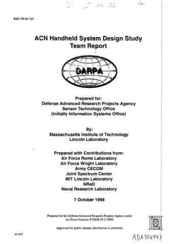
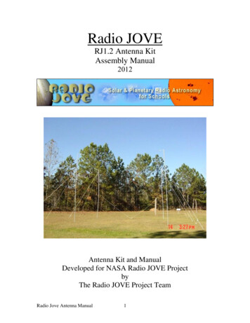
20M,4.8KΩ 15M)20M,4.8KΩ 15M)In general, any combination of chokes can be used in series to provide the desired choking impedanceover the desired bandwidth. Their combined choking impedance will be the sum of their resistancevalues on each band. For example, two 12-turn RG400 or Teflon chokes provide at least 8KΩ from 80 to15M and 6KΩ on 10M. Combining 14 and 17 turn RG400 chokes provides more than 8KΩ on 160M,about 12KΩ on 80M, 8KΩ on 40M, 7KΩ on 30M, and 5KΩ on 20M.Building a Common-Mode ChokeFor our end fed wire we were faced with a dilemma. What frequency should we target? Given thatmost of the noise we were hearing is typically in the lower part of the HF band we opted to build achoke that would cover as much of the lower part of the HF band as possible from 80-meters up. So weopted for 16 turns of RG-58 around a single FT240-31 core. Again this is a really simple device to build.Here’s is what you will need:From Amazon:1. One FT240-31. The Amazon description is “Toroid Core FT240-31 Ferrite” and costs about 132. Two SO-239From Lowes:1. One grey plastic Electrical box2. Four 6X32X3/4 Stainless Steel screws with Nylock nuts.From our junk we will need about a 4’ length of RG-58 coaxial cable. If you need to build a choke withmore power handling capability use either RG400 or Teflon coated wire or #12 insolated wire. Insolatedwire is what you will find in common house wire aka: Romax. I chose to build my choke out of RG400given its power handling ability. See Figure 5 for a picture of our choke.
Figure 5: Common Mode Choke made using RG-400Our Results: We took noise reading before and after installing the choke. Our results can be found inTable 2.Band80 meters40 meters20 meters15 meters10 metersPre InstallationS4S8S9S6S6Post Installation S1S4S3-4S4-5S5Change4 S units4 S units4-5 S units1 S unit1 S unitTable 4: Noise Level ResultsThe results were as expected. The most improvement appeared from 80 to 20 meters with only a smallchange for 10 and 15 meters. Given out design this was the expected behavior. We also noticed a smallchange in the SWR reading but they were still well in range of the built in tuner in the FT-1000MP.Summary
In this article we have covered a lot of ground from the installation of an end fed wire to the in’s andouts of baluns, ununs and Common Mode Chokes. Nearly every ham station can benefit by making suretheir aerial is properly fed and that common mode currents have been minimized. The key takeawaysfrom this article are:1. All antennas installations will have some common mode currents flowing on the coaxial cable.In some case it will be noticeable in others it not so much.2. Baluns, Ununs, and Chokes are easy to build and not necessarily expensive.3. An End Fed Wire can make a good antenna even where space is limited.4. An end Fed Wire needs to be properly fed using a 9:1 unun and CMC’s minimized by including aCMC choke.If you are interested in finding out more about Chokes, Baluns and Ununs visit the following web ://www.hfkits.com/
connected to the electrical mast where the power comes into his house. That end would be about 20 feet in the air. . The canon is made from 2” PV and a length of ¾ PVC for the barrel. The valve is a gas line ball valve. The reel is an old fishing reel wound with 50 lb. S