Transcription
FOREWORDThe Gypsum Association FIRE RESISTANCE DESIGN MANUAL is referenced by thefollowing code and standards writing organizations:INTERNATIONAL BUILDING CODE, published by:International Code Council, Inc.5203 Leesburg Pike, Suite 600Falls Church, Virginia 22041(See footnote a, Tables 719.1a, 719.1b, and 719.1c)BOCA NATIONAL BUILDING CODE, published by:Building Officials and Code Administrators International, Inc.4051 West Flossmoor RoadCountry Club Hills, Illinois 60478-5795(See Chapters 7, 12, and 25, Commentary to the BOCA National Building Code)UNIFORM BUILDING CODE, published by:International Conference of Building Officials5360 Workman Mill RoadWhittier, California 90601(See footnote a, Tables No. 7-A, -B, and -C, and Appendix Section 1209)STANDARD BUILDING CODE, published by:Southern Building Code Congress International, Inc.900 Montclair RoadBirmingham, Alabama 35213-1206(See Section 701.5.2)THE NATIONAL FIRE CODES, published by:National Fire Protection Association1 Batterymarch ParkP.O. Box 9101Quincy, Massachusetts 02269-9101(See NFPA 90A, NFPA 101, NFPA 221, NFPA 5000, and the Life Safety Code Handbook)The FIRE RESISTANCE DESIGN MANUAL is also referenced in the code documents ofmajor jurisdictions in the United States such as South Florida, Chicago, Los Angeles, NewYork City, and the State of New York. In addition, the Manual has been recognized in majorjurisdictions in Canada.GA-600-20033
TABLE OF CONTENTSFOREWORD . . . . . . . . . . . . . . . . . . . . . . . . . . . . . . . . . . . . . . . . . . . . . . . . . . . . . . . . . . . . . . . . . . . . . . . .3TABLE OF CONTENTS . . . . . . . . . . . . . . . . . . . . . . . . . . . . . . . . . . . . . . . . . . . . . . . . . . . . . . . . . . . . . . .4INTRODUCTION . . . . . . . . . . . . . . . . . . . . . . . . . . . . . . . . . . . . . . . . . . . . . . . . . . . . . . . . . . . . . . . . . . . . .6SECTION I - USE OF THIS MANUAL AND GENERAL EXPLANATORY NOTES . . . . . . . . . .7Overview . . . . . . . . . . . . . . . . . . . . . . . . . . . . . . . . . . . . . . . . . . . . . . . . . . . . . . . . . . . . . . . . . . . . . . . . . .7Description of Terms . . . . . . . . . . . . . . . . . . . . . . . . . . . . . . . . . . . . . . . . . . . . . . . . . . . . . . . . . . . . . . . . . .7General Explanatory Notes . . . . . . . . . . . . . . . . . . . . . . . . . . . . . . . . . . . . . . . . . . . . . . . . . . . . . . . . . . . . .8Testing Agencies . . . . . . . . . . . . . . . . . . . . . . . . . . . . . . . . . . . . . . . . . . . . . . . . . . . . . . . . . . . . . . . . . . . .10Product Identification . . . . . . . . . . . . . . . . . . . . . . . . . . . . . . . . . . . . . . . . . . . . . . . . . . . . . . . . . . . . . . . . .11Abbreviations . . . . . . . . . . . . . . . . . . . . . . . . . . . . . . . . . . . . . . . . . . . . . . . . . . . . . . . . . . . . . . . . . . . . . .12SECTION II - REQUIREMENTS FOR FIRE PROTECTION . . . . . . . . . . . . . . . . . . . . . . . . . . . . . .13Fire Resistive Properties of Gypsum . . . . . .Type X Gypsum Board . . . . . . . . . . . . . . . .Performance of Gypsum Plaster . . . . . . . . .Fire Resistance Tests . . . . . . . . . . . . . . . . .Wall and Partition Systems . . . . . . . . . . . . .Area Separation Walls (Party/Fire Walls) . . .Floor-Ceiling and Roof-Ceiling Systems . . .Ceiling Openings . . . . . . . . . . . . . . . . . . .Beam, Girder, and Truss Protection SystemsContinuous Ceiling Protection . . . . . . . . .Individual Encasement Protection . . . . . .Column Protection Systems . . . . . . . . . . . .Fire Blocking . . . . . . . . . . . . . . . . . . . . . . . .Smoke Barriers . . . . . . . . . . . . . . . . . . . . . .Perimeter Relief and Control Joints . . . . . . .Surface Burning Characteristics . . . . . . . . CTION III - SOUND CONTROL . . . . . . . . . . . . . . . . . . . . . . . . . . . . . . . . . . . . . . . . . . . . . . . . . . . .20Sound Insulation . . . . . . . . . . . . . . . . . . . . . . . . . . . . . . . . . . . . . . . . . . . . . . . . . . . . . . . . . . . . . . . . . . . .20Sound Transmission Loss Tests . . . . . . . . . . . . . . . . . . . . . . . . . . . . . . . . . . . . . . . . . . . . . . . . . . . . . . . .22Impact Noise Test . . . . . . . . . . . . . . . . . . . . . . . . . . . . . . . . . . . . . . . . . . . . . . . . . . . . . . . . . . . . . . . . . . .23SECTION IV - LIMITING HEIGHTS (Nonload-Bearing) . . . . . . . . . . . . . . . . . . . . . . . . . . . . . . . . .24SECTION V - FIRE RESISTANCE AND SOUND CONTROL SYSTEMS . . . . . . . . . . . . . . . . . .26INDEX TO SYSTEMS BY STC RATING . . . . . . . . . . . . . . . . . . . . . . . . . . . . . . . . . . . . . . . . .LISTING OF DELETED SYSTEMS . . . . . . . . . . . . . . . . . . . . . . . . . . . . . . . . . . . . . . . . . . . . .LISTING OF NEW SYSTEMS . . . . . . . . . . . . . . . . . . . . . . . . . . . . . . . . . . . . . . . . . . . . . . . . .WALL AND PARTITION SYSTEMS . . . . . . . . . . . . . . . . . . . . . . . . . . . . . . . . . . . . . . . . . . . .Walls and Interior Partitions, Noncombustible, 1-HOUR . . . . . . . . . . . . . . . . . . . . . . . . . . . .Walls and Interior Partitions, Noncombustible, 2-HOUR . . . . . . . . . . . . . . . . . . . . . . . . . . . .Walls and Interior Partitions, Noncombustible, 3-HOUR . . . . . . . . . . . . . . . . . . . . . . . . . . . .Walls and Interior Partitions, Noncombustible, 4-HOUR . . . . . . . . . . . . . . . . . . . . . . . . . . . .Walls and Interior Partitions, Wood-Framed, 1-HOUR . . . . . . . . . . . . . . . . . . . . . . . . . . . . . .Walls and Interior Partitions, Wood-Framed, 2-HOUR . . . . . . . . . . . . . . . . . . . . . . . . . . . . . .Chase Walls, Noncombustible, 1-HOUR . . . . . . . . . . . . . . . . . . . . . . . . . . . . . . . . . . . . . . . .Chase Walls, Noncombustible, 2-HOUR . . . . . . . . . . . . . . . . . . . . . . . . . . . . . . . . . . . . . . . .Chase Walls, Wood-Framed, 1-HOUR . . . . . . . . . . . . . . . . . . . . . . . . . . . . . . . . . . . . . . . . .Chase Walls, Wood-Framed, 2-HOUR . . . . . . . . . . . . . . . . . . . . . . . . . . . . . . . . . . . . . . . . .Movable and Office Partitions, 1-HOUR . . . . . . . . . . . . . . . . . . . . . . . . . . . . . . . . . . . . . . . .Movable and Office Partitions, 2-HOUR . . . . . . . . . . . . . . . . . . . . . . . . . . . . . . . . . . . . . . . .Shaft Walls, 1-HOUR . . . . . . . . . . . . . . . . . . . . . . . . . . . . . . . . . . . . . . . . . . . . . . . . . . . . . .4. . . .26. . . .28. . . .28. . . .29. . . .29. . . .39. . . .47. . . .49. . . .52. . . .60. . . .63. . . .63. . . .65. . . .66. . . .67. . . .70. . . .71GA-600-2003
Shaft Walls, 2-HOUR . . . . . . . . . . . . . . . . . . . . . .Shaft Walls, 3-HOUR . . . . . . . . . . . . . . . . . . . . . .Shaft Walls, 4-HOUR . . . . . . . . . . . . . . . . . . . . . .Exterior Walls, 1-HOUR . . . . . . . . . . . . . . . . . . . .Exterior Walls, 2-HOUR . . . . . . . . . . . . . . . . . . . .Metal Clad Exterior Walls, 1-HOUR . . . . . . . . . . .Metal Clad Exterior Walls, 2-HOUR . . . . . . . . . . .Area Separation Walls (Party/Fire Walls), 2-HOURArea Separation Walls (Party/Fire Walls), 3-HOUR.73.83.84.85.89.93.94.96.99FLOOR-CEILING SYSTEMS . . . . . . . . . . . . . . . . . . . . . . . . . . . . . . . . . . . . . . . . . . . . . . . . . . . . . . . . .100Floor-Ceiling Systems, Noncombustible, 1-HOUR . . . . . . . . . . . . . . . . . . . . . . . . . . . . . . . . . . . . . . . .100Floor-Ceiling Systems, Noncombustible, 1½-HOUR . . . . . . . . . . . . . . . . . . . . . . . . . . . . . . . . . . . . . . .101Floor-Ceiling Systems, Noncombustible, 2-HOUR . . . . . . . . . . . . . . . . . . . . . . . . . . . . . . . . . . . . . . . .101Floor-Ceiling Systems, Noncombustible, 3-HOUR . . . . . . . . . . . . . . . . . . . . . . . . . . . . . . . . . . . . . . . .103Floor-Ceiling Systems, Noncombustible, 4-HOUR . . . . . . . . . . . . . . . . . . . . . . . . . . . . . . . . . . . . . . . .104Floor-Ceiling Systems, Steel-Framed, Wood Floor, 1-HOUR . . . . . . . . . . . . . . . . . . . . . . . . . . . . . . . . .105Floor-Ceiling Systems, Steel-Framed, Wood Floor, 2-HOUR . . . . . . . . . . . . . . . . . . . . . . . . . . . . . . . . .107Floor-Ceiling Systems, Wood-Framed, 1-HOUR . . . . . . . . . . . . . . . . . . . . . . . . . . . . . . . . . . . . . . . . . .108Floor-Ceiling Systems, Wood-Framed, 1½-HOUR . . . . . . . . . . . . . . . . . . . . . . . . . . . . . . . . . . . . . . . . .118Floor-Ceiling Systems, Wood-Framed, 1¾-HOUR . . . . . . . . . . . . . . . . . . . . . . . . . . . . . . . . . . . . . . . . .119Floor-Ceiling Systems, Wood-Framed, 2-HOUR . . . . . . . . . . . . . . . . . . . . . . . . . . . . . . . . . . . . . . . . . .119ROOF-CEILING SYSTEMS . . . . . . . . . . . . . . . . . . . . . . . . . . . . . . . . . . . . . . . . . . . . . . . . . . . . . . . . . .121Roof-Ceiling Systems, 1-HOUR . . . . . . . . . . . . . . . . . . . . . . . . . . . . . . . . . . . . . . . . . . . . . . . . . . . . . .121Roof-Ceiling Systems, 2-HOUR . . . . . . . . . . . . . . . . . . . . . . . . . . . . . . . . . . . . . . . . . . . . . . . . . . . . . .122COLUMN PROTECTION SYSTEMS .Columns, Noncombustible, 1-HOURColumns, Noncombustible, 2-HOURColumns, Noncombustible, 3-HOURColumns, Noncombustible, 4-HOUR.BEAM, GIRDER, AND TRUSS PROTECTION SYSTEMSBeams, Girders and Trusses; Noncombustible, 1-HOURBeams, Girders and Trusses; Noncombustible, 2-HOURBeams, Girders and Trusses; Noncombustible, 3-HOURBeams, Girders and Trusses; Noncombustible, ENDIX . . . . . . . . . . . . . . . . . . . . . . . . . . . . . . . . . . . . . . . . . . . . . . . . . . . . . . . . . . . . . . . . . . . . . . . .141Commonly Used Metric Conversions . . . . . . . . . . . . . . . . . . . . . . . . . . . . . . . . . . . . . . . . . . . . . . . . . . . .141GA-600-20035
INTRODUCTIONNOTE: This Introduction constitutes an essential part of the system descriptions contained inSection V. It is important that theuser be familiar with this introductory material.WHETHER A MEMBER OF THEGYPSUM ASSOCIATION OR NOT,PROVIDED THE PRODUCTSMEET THE APPROPRIATE STANDARDS LISTED IN SECTION IAND, WHEN APPLICABLE, THEREQUIREMENTS SET FORTH INSECTION II.This Manual is a convenient anduseful specification aid for anyoneconcerned with the design, construction, or inspection of fire resistive and sound control systems. Design information is quickly and easily determined. Comparison of thesecharacteristics allows the user to bemore accurate in meeting designand code requirements. The dataprovided are especially useful tobuilders, architects, code officials,fire service, and insurance personnel.To maintain industry-wide qualityassurance standards for gypsumboard defined in this Manual as"type X," the Gypsum Associationrequires that all companies listingproprietary tests or systems, or relying on the generic systems in thismanual, shall subscribe to an ongoing third-party, in-plant product inspection and labeling service. Additionally, each member companymakes annual written certification tothe Gypsum Association that itsproducts manufactured for use insystems listed in this Manual continue to be inspected and labeled byan independent third-party testingservice as listed on page 10.The systems in this Manual utilize gypsum products to provide fireresistance to walls, partitions, floorceilings, roof-ceilings, columns,beams, girders, and trusses. Systems are classified according totheir typical uses and their fire-resistance ratings. Walls, partitions, andfloor-ceiling systems are furtherclassified by Sound TransmissionClass (STC) or Field Sound Transmission Class (FSTC). The ImpactInsulation Class (IIC) is included formany wood framed floor-ceiling systems.WHERE THE WORD "PROPRIETARY" APPEARS IN SYSTEMDESCRIPTIONS EITHER THESYSTEM OR ONE OR MORE OFITS COMPONENTS IS CONSIDERED PROPRIETARY. EACHPROPRIETARY SYSTEM SHALLBE BUILT UTILIZING THE COMPONENTS SPECIFIED BY THECOMPANY OR COMPANIES LISTED UNDER THE DETAILED DESCRIPTION FOR THAT SYSTEM.ALL OTHER SYSTEMS AREGENERIC. GENERIC SYSTEMSARE APPLICABLE TO THE PRODUCTS OF ANY MANUFACTURER,6Fire-resistance ratings, STCs,FSTCs, and IICs are the results oftests conducted on systems composed of specific materials put together in a specified manner. Substitution of other materials or deviation from the specified constructioncould adversely affect performance.For example, if batt or blanket insulation is shown, then it is a requiredcomponent of the system. In eachsystem containing batt or blanket insulation the insulation is specified tobe either mineral or glass fiber and,for fire resistance, the system shallbe constructed using the type specified. Mineral fiber or glass fibershall not be arbitrarily added tofloor-ceiling or roof-ceiling systemsto increase either STCs or R-values.This practice has been shown to reduce the fire-resistance rating. Theaddition of up to 163/4 inches of 0.5pcf glass fiber insulation (R-40), either batt or loose-fill, to any 1- or 2hour fire resistance rated floor-ceiling or roof-ceiling system having acavity deep enough to accept the insulation is permitted provided thatone additional layer of either 1/2 inchor 5/8 inch type X gypsum board isapplied to the ceiling. The additional layer of gypsum board shall beapplied as described for the facelayer of the tested system exceptthat the fastener length shall be increased by not less than the thickness of the additional layer of gypsum board.The detailed descriptions for thesystems included in this Manual aresummaries. For complete information on the systems or componentstested, the listing or test reportshould be reviewed. Details regarding generic systems may be requested from the Gypsum Association; details on proprietary systemsare available from the companieslisted for those systems.References to ASTM standards,CSA standards, CAN/ULC standards, or other standards refer tothe respective standard in effect onthe date that the test was performed. Each test reference contains the test report date.The information in this Manual isbased on characteristics, properties,and performance of materials andsystems obtained under controlledtest conditions as set forth in the appropriate standards in effect at thetime of the test. The Gypsum Association and its member companiesmake no warranties or other representations as to the characteristics,properties, or performance of anymaterials or systems in actual construction. No warranty or representation is made that any material orcomponent of any system, otherthan the gypsum material used insuch system, conforms to any standard or standards.GA-600-2003
SECTION IUSE OF THIS MANUAL ANDGENERAL EXPLANATORY NOTESOVERVIEWThe systems are divided into fivemajor categories and listed in theTable of Contents on pages 4 an 5under these headings:-Wall and Partition SystemsFloor-Ceiling SystemsRoof-Ceiling SystemsColumn Protection SystemsBeam, Girder, and TrussProtection SystemsIn the case of walls and partitions, floor-ceilings, and roof-ceilings, noncombustible systems arelisted first, followed by wood-framedsystems. They are further subdivided by fire-resistance rating startingwith one hour and increasing. STCs(or FSTCs) are listed in descendingorder. Where sound test data arenot available, estimated STCs arebased on evaluations of similar systems for which test data are available.Each system has been assigneda reference number - the GA FileNumber. Cite this GA File Number inspecifications and on plans, or whenmaking inquiries about specific systems.All system descriptions contain abrief list of the major components ofthe system followed by a more detailed description. The detailed descriptions of interior systems beginNOTE: Listing of a system in aspecific category in this Manual isnot intended to limit its use to thatcategory (see General Explanatory Note 13 on page 9). However,this shall not be interpreted toimply that vertical systems, suchas walls and partitions, are permitted to arbitrarily be used in a horizontal orientation. In addition, themanufacturer shall be consultedfor other products which satisfythe fire and sound requirementsshown for the systems.GA-600-2003with the material exposed to the testfire and its method of attachment,followed by a description of theframing members and their methodsof installation. Finally, the unexposed side and its method of attachment is described.Where unsymmetrical systemswere tested from one side only, theside exposed to the test fire is indicated by the words "Fire Side" onthe system detail. When documentation is available to show that thewall was tested with the least fire-resistive side exposed to the test fire,the wall need not be subjected totests from the opposite side and a"Fire Side" is not specified. All floorceiling and roof-ceiling systemswere tested with fire exposure onthe ceiling side.When mineral or glass fiber insulation was a basic component of afire tested system, it is included inthe description as an integral part ofthe system. The insulation thickness, type, and density are described, and both the fire and sounddetails show fibrous insulation. If theinsulation was used solely to increase the STC, the fibrous insulation is shown only in the sound detail. When the insulation is not needed for the fire-resistance rating, butis used to improve the STC of thesystem, the last sentence of the detailed description states, "Soundtested with [mineral] [glass] fiber insulation." (See General ExplanatoryNotes 10, 11, and 12 on pages 8and 9.)Unless indicated otherwise, allload-bearing wood stud systemswere tested while being subjected tothe maximum load allowed by design under nationally recognized design criteria at the time of the test.Due to an increase in the maximumallowable loading in the NationalDesign Specifications (1982 andlater editions), the American Forestand Paper Association issued thefollowing statement:Where a load-bearing firerated wood stud wall assembly contained in this Manualis specifically designed forstructural capacity, the designvalue in compression parallelto grain adjusted for slenderness ratio (Fc') used in suchanalysis shall be taken as 78percent of the maximum Fc'value determined in accordance with normal designpractice but shall not exceed78 percent of the Fc' value forsuch member having a slenderness ratio (le/d) of 33.DESCRIPTION OF TERMS USEDIN THIS MANUALGypsum Board - defined in ASTMC 11, Standard Terminology Relating to Gypsum and RelatedBuilding Materials and Systems,as "the generic name for a family of sheet products consisting ofa noncombustible core primarilyof gypsum with paper surfacing."Gypsum board may be furtherdescribed as follows:Regular Gypsum Board - a gypsum board with naturally occurring fire resistance fromthe gypsum in the core; orType X Gypsum Board - a gypsum board with special coreadditives to increase the natural fire resistance of regulargypsum board.NOTE: Where the word “proprietary” appears in system descriptions either the system or one ormore of its components is considered proprietary. Each proprietarysystem shall be built utilizing thecomponents specified by the company or companies listed underthe detailed description for thatsystem.7
Limited Load-Bearing - this meansthat a constant superimposedload was applied to the testspecimen throughout the fire testto simulate a design load lessthan 78% of the maximum allowable design load.Load-Bearing - unless otherwisenoted in the detailed description,this means that a constant superimposed load was applied tothe test specimen throughout thefire test to simulate 78% or moreof the maximum allowable design load.Mineral Fiber - refers to either rockor slag wool products.Metal Studs - refers to nominal 25gage steel studs and runners(track) manufactured to complywith ASTM C 645 unless otherwise specified in the detailed description.(NLB) - nonload-bearing.GENERAL EXPLANATORYNOTES1. All dimensions, weights, temperatures, and pressures are inU.S. customary units. For commonly used metric (SI) conversions refer to the Appendix onpage 141 and IEEE/ASTMSI 10-2002, Standard for Useof the International System ofUnits (SI): The Modernized Metric System.2. Nails shall comply with ASTMF 547 or ASTM C 514. Othernails, suitable for the intendeduse, and having dimensions notless than those specified in thisManual shall be permitted assubstitutions.3. Fasteners installed along theedges of gypsum board shall beplaced along the paper boundedges on the long dimension ofthe board. Fasteners at the endshall be placed along mill orfield cut ends on the short dimension. Fasteners on theperimeter of the board shall beplaced along both edges andends.4. Screws meeting ASTM C 1002shall be permitted to be substituted for the prescribed nails,8one for one, when the lengthand head diameter of thescrews equal or exceed those ofthe nails specified in the testedsystem and the screw spacingdoes not exceed the spacingspecified for the nails in thetested system.5. Vertically applied gypsum boardshall have the edges parallel toframing members. Horizontallyapplied gypsum board shallhave the edges at right anglesto the framing members. Intermediate vertical framing members are those between the vertical edges or ends of the board.6. Unless otherwise specified, theface layers of all systems, except those with predecorated ormetal covered surfaces, shallhave joints taped (minimumLevel 1 as specified in GA-214,Recommended Levels of Gypsum Board Finish) and fastenerheads treated. Base layers inmulti-layer systems shall not berequired to have joints taped.7. When a fire-resistance ratedpartition extends above the ceiling, the gypsum board joints occurring above the ceiling neednot be taped and fastenersneed not be covered when all ofthe following conditions are met.a. The ceiling is part of a fireresistance rated floor-ceiling or roof-ceiling system;b. All vertical joints occur overframing members;c.Horizontal joints are eitherstaggered 24 inches o.c. onopposite sides of the partition, or are covered withstrips of gypsum board notless than 6 inches wide; orthe partition is a two-plysystem with joints staggered 16 inches or 24 inches o.c.; andd. The partition is not part of asmoke or sound control system.Where joint treatment is discontinued at or just above the ceiling line, the vertical joint shall becross taped at this location toreduce the possibility of jointcracking.8. Metallic outlet boxes shall bepermitted to be installed in woodand steel stud walls or partitionshaving gypsum board facingsand classified as two hours orless. The surface area of individual boxes shall not exceed16 square inches. The aggregate surface area of the boxesshall not exceed 100 squareinches in any 100 square feet.Boxes located on oppositesides of walls or partitions shallbe in separate stud cavities andshall be separated by a minimum horizontal distance of 24inches. Approved nonmetallicoutlet boxes shall be permittedas allowed by local code.9. Water-resistant gypsum backing board shall be installed overor as part of the fire-resistancerated system in shower and tubareas to receive ceramic orplastic wall tile or plastic finished wall panels. When fire orsound ratings are necessary,the gypsum board required forthe rating shall extend down tothe floor behind fixtures so thatthe construction will equal thatof the tested system. (See Figure 1 on page 9.)10. When not specified as a component of a fire tested wall or partition system, mineral fiber,glass fiber, or cellulose fiber insulation of a thickness not exceeding that of the stud depthshall be permitted to be addedwithin the stud cavity.11. In floor-ceiling or roof-ceilingsystems, the addition or deletion of mineral or glass fiber insulation in ceiling joist spacescould possibly reduce the fireresistance rating. The additionof up to 163/4 inches of 0.5 pcfglass fiber insulation (R-40), either batt or loose-fill, to any 1- or2-hour fire resistance ratedfloor-ceiling or roof-ceiling system having a cavity deepenough to accept the insulationis permitted provided that oneadditional layer of either 1/2 inchtype X or 5/8 inch type X gypsumGA-600-2003
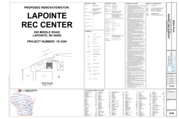
board is applied to the ceiling.The additional layer of gypsumboard shall be applied as described for the face layer of thetested system except that thefastener length shall be increased by not less than thethickness of the additional layerof gypsum board.12. In each system containing battor blanket insulation the insulation is specified to be either mineral or glass fiber and, for fireresistance, the system shall bebuilt using the type specified.13. Although the systems arearranged in general groupings(i.e. walls and interior partitions,floor-ceilings,roof-ceilings,etc.), this is not intended to limittheir use only to the specific category in which they are listed.For example, systems listed asshaft walls shall be permitted tobe used as interior partitions.However, systems tested vertically (walls and partitions) shallnot be permitted to be arbitrarilyused in a horizontal orientation.14. Metal studs and runners arenominal 25 gage unless otherwise specified.15. Greater stud sizes (depths)shall be permitted to be used inmetal- or wood-stud systems.Metal studs of heavier gagethan those tested shall be permitted. The assigned rating ofany load-bearing system shallalso apply to the same systemwhen used as a nonload-bearing system. Indicated stud spacings are maximums.16. Specified floor-ceiling and roofceiling framing sizes or truss dimensionsareminimums.Greater joist or truss sizes(depths) shall be permitted to beused in metal- or wood-framedsystems. Indicated joist andtruss spacings are maximums.17. Within design limitations, thedistance between parallel rowsof studs, such as in a chasewall, shall be permitted to be increased beyond that tested.When stud cavities in walls constructed of parallel rows of steelstuds exceed 91/2 inches andcross bracing is required thecross bracing shallbe fabricated fromsteel studs.18. Systems tested with metal furring channels attached directlyto the bottom chords of steelbeams, bar joists, or woodtrusses or framing shall be permitted to be suspended. Generally, furring channels are attached to 11/2 inch cold rolledcarrying channels 48 inches o.c.suspended from joists by 8gage wire hangers spaced notgreater than 48 inches o.c.19. Floor-ceiling and roof-ceilingsystems were fire tested at lessthan 36 inches total depth. However, the total depth of the systems, with either directly attached or suspended ceilingmembranes, shall be permittedto extend greater than 36 inches.20. Where laminating compound isspecified, taping, all-purpose,and setting type joint compounds shall be permitted.21. Additional layers of type X orregular gypsum board shall bepermitted to be added to anysystem.22. When not specified as a component of a fire-resistance ratedwall or partition system, woodstructural panels shall be permitted to be added to one orboth sides. Such panels shall bepermitted to be applied either asa base layer directly to the framing (under the gypsum board),as a face layer (over the facelayer of gypsum board), or between layers of gypsum boardin multi-layer systems. Whensuch panels are applied underthe gypsum board or betweenlayers of gypsum board thelength of the fasteners specifiedfor the attachment of the gypsum board applied over thewood structural panels shall beincreased by not less than thethickness of the wood structuralpanels. Fastener spacing for thegypsum board and the numberof layers of gypsum board shallbe as specified in the systemdescription.Figure 1Section Through Typical One-Hour SystemGA-600-20039
TESTING AGENCIESEach detailed description is accompanied by a cross-section detailof the system. Also included is design information giving total thickness, limiting height where appropriate, and approximate weight of thesystem in pounds per square foot.Fire and sound test references identifying the agency which certified thetest as well as a report number anddate are also provided (see Tables Iand II).TABLE IFIRE TESTING AGENCIESBMSBuilding Materials &Structures, National Bureauof Standards (now NationalInstitute of Standards andTechnology)ACIAcoustical Cons
BOCA NATIONAL BUILDING CODE, published by: Building Officials and Code Administrators International, Inc. 4051 West Flossmoor Road Country Club Hills, Illinois 60478-5795 (See Chapters 7, 12, and 25, Commentary to the BOCA National Building Code) UNIFORM BUILDING CODE,published by: International Conferenc