Transcription
derstandTo help unotations,the 3D anncludes athe book intorial oncomplete tuRKS MBDSOLIDWOThe book coversthe changes andimprovements in theASME Y14.5-2018standard
Technical product documentation using ISO GPS - ASME GD&T standardsFOREWORDDesigners create perfect and ideal geometries through drawings or by means ofComputer Aided Design systems, but unfortunately the real geometrical featuresof manufactured components are imperfect, in terms of form, size, orientation andlocation.Therefore, technicians, designers and engineers need a symbolic language thatallows them to define, in a complete, clear and unambiguous way, the admissiblevariations, with respect to the ideal geometries, in order to guarantee functionalityand assemblability, and to turn inspection into a scientifically controllable process.The Geometric Product Specification (GPS) and Geometrical Dimensioning and Tolerancing (GD&T) languages are the most powerful tools available to link the perfectgeometrical world of models and drawings to the imperfect world of manufacturedparts and assemblies.This book is intended for designers, process engineers and CMM operators, and ithas the main purpose of presenting the ISO GPS rules and concepts. Moreover, thedifferences between ISO GPS and the American ASME Y14.5 standard are shownas a guide and reference for the drawing interpretation of the most common dimensioning and tolerancing notations.A complete SolidWorks MBD tutorial has been added to the appendix of this book:SOLIDWORKS Model Based Definition (MBD) is a drawingless manufacturing solution that is embedded inside a SOLIDWORKS user interface. It helps companiesdefine, organise and publish product and manufacturing information (PMI) in a 3Dformat that complies with international standards.The book covers the changes and improvements in the ASME Y14.5-2018 standardThe author, Professor Stefano Tornincasa, has carried out research activitiesfor over thirty years in the field of functional design and geometric tolerances.He was President of the ADM Improve Association (Innovative Methods inPROduct design and deVElopment) from 2011 to 2015 and has publishedmore than 180 national and international scientific papers.He is co-author of the best-selling book on Industrial Technical Drawing, whichis currently adopted in the design courses of most Italian universities (E. Chirone,S. Tornincasa, Industrial Engineering Design, Volumes I and II, ed. Il capitelloTorino).Professor Tornincasa has conducted training courses on GD&T in many of themain manufacturing companies in Italy, and it is from this activity that he hasderived his skill and experience in functional design.His other research topics have been focused on product development, cycleinnovation through digital models and virtual prototyping methodologies (PLM)http://webd.polito.it/workbook/3
Technical product documentation using ISO GPS - ASME GD&T standards2. CLASSIFICATION AND INDICATIONOF GEOMETRIC TOLERANCESPutting off the discussion of new rules pertaining to the GD&T methodologyto the next section, it is here opportune to recall some basic definitions in thecontext of what is now defined, in the rules and in practice, as GPS, that is,Geometrical Product Specification.Figure 8 shows some basic concepts of ISO 14460/1, which is often referredto in the ISO 1101 standard as the definition of Integral and derived features. Fig. 8. The ISO standardDrawing-solid modelManufacturingNominal integralfeatureNominal derivedfeature (axis)Inspection ralfeatureReal tractedintegralfeatureprovides terms that allowan engineer to understandthe impact of the drawingspecifications on inspection.A nominal integral feature is atheoretically exact feature thathas been defined in a technicaldrawing. A nominal derivedfeature is an axis that hasbeen derived from one or moreintegral features. Extracted andassociated features are partsof the inspection domain. Anassociated integral feature is anintegral feature of a perfect formassociated with the extractedintegral feature. An associatedderived feature is an axis orcenterplane of a perfect form.The integral surface is a surface or line on a feature. The derived featureis a centre point, median line or median surface derived from one or moreintegral features.A modelled cylinder is an integral feature, while the cylinder axis is anabstract element that can be derived from the cylindrical geometry. A derivedor integral feature can be either nominal or real (that is, the manufacturedelement). In metrology, through the use of a CMM measuring machine, theextracted feature (integral or derived, that is, an approximated representationof the real feature, which is acquired by extracting a finite number of points)is obtained from the real (integral) feature. A perfect associated feature (acylinder or the derived axis, which can be used, for example, as a Datum)can thus be obtained from the extracted features. Geometrical features can befound in three domains: the specification domain, where several representations of the futureworkpiece are imaged by the designer; the workpiece domain, that is, the physical domain; the inspection domain, where a representation of a given workpiece isused through the sampling of the workpiece by measuring instruments.9
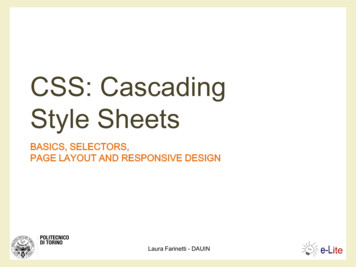
Technical product documentation using ISO GPS - ASME GD&T standards16,9dis minimtan umceFig. 52. Verification procedure of a shaft according tothe envelope principle or ASME Rule#1. The minimummaterial condition is controlled by an external gauge (themeasurement between two opposite points), while themaximum material condition is checked by means of anenvelope of perfect form with MMC dimensions.Envelope ofperfect formEnvelope ofperfect form(maximumcylinder)44,2 maximumtwo-pointdistances Fig. 53. Verification procedure of a hole according to the envelope principle. The minimum material condition iscontrolled by an internal gauge (measured between two opposite points), while the maximum material condition ischecked by means of a pin with the MMC dimensions.appropriate in the case of mating, may be restrictivefor all the other geometrical features, and maymake it necessary, in the latter case, to furnish anindication of exception (the ASME standards haveintroduced the È symbol, see Fig. 55), with theconsequence of a source of ambiguity being createdas it is not possible to be certain that the absenceof such an indication depends on the choices ofthe designer or rather on an oversight within acomplex technical document.Apart from this problem, the verification of theenvelope principle, which requires the use offunctional gauges1 or controls carried out bymeans of measurement machines that have1Gage in ASMEASMEdrawingISOdrawingFig. 54. The envelope requirement in the ISO standardis indicated by means of a circled E, which is placednext to the tolerance dimension; the hole has aperfect form when all the local diameters are in themaximum material conditions, that is, 18 mm.Fig. 55. If onewishes to apply theindependency principlein ASME drawings, it isnecessary to insert theindependence symbol Inext to the dimension.33
Technical product documentation using ISO GPS - ASME GD&T standardsDatum system taken from two cylinders and a plane1. first associated feature without a constraint2. second associated feature with a perpendicularity constraint from the firstassociated feature3. third associated feature with a perpendicularity constraint from the firstassociated feature (and parallelism constraint from the second one)Resulting datum system4. plane which is the first associated feature5. point of intersection between the plane and the axis of the second associatedfeature6. straight line which is the intersection between the associated plane and theplane containing the two axes The ASME Y14.5 standard makes adistinction between the concept of adatum feature, a datum and a datumfeature simulator1 A datum is an abstractgeometrical feature (point, axis or planefrom which a dimensional measurementis made), which represents the perfectcounterpart of a datum feature (e. g.an ideal plane or the axis of the perfectgeometrical counterpart).The simulated datums are conceptuallyperfect (physically almost perfect), andthey represent a bridge between theimperfect real world of datum features andthe perfect imaginary world of datums.Ultimately, it is opportune to distinguishbetween the real datum feature of theworkpiece (named datum feature) andthe datum, the equivalent theoreticaldatum (plane, axis or centerplane),simulated by the associated inspection ormanufacturing equipment.The datum system of a tool machineis shown in Figure 85: the productionequipment has the duty of aligning thefeatures of the workpiece with the datumsof the machine (for example, datum featureA is aligned with the clamping machineand datum feature B is made to coincide1datumfeature Adatumfeature B Fig. 85. No datums exist on a workpiece but they are simulatedby the datum feature system of the tool machine.In the ASME Y14.5:2018 the term “theoretical datum feature simulator” was replaced with “true geometric counterpart”47
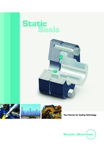
THE STRAIGHTNESS TOLERANCE INTHE ASME STANDARDcentre points of each cross section By default, the ASME Y14.5 standard appliesthe envelope requirement, and the rule shownin Figure 164 therefore applies. However, it isnecessary to pay particular attention, becausewhenever the straightness tolerance is appliedto a derived median line, Rule #1 is no longerapplicable, that is, the component does not havea perfect form at the maximum material (and therule in Figure 165 is therefore valid).Figure 170 shows, for the case of the shaft inFigure 165, the concept of derived median line,obtained from the set of central points of thesingular perpendicular sections of the axis of thesmallest restricted cylinder: the derived medianline should fall within a cylinder centred on thenominal axis of an envelope of perfect form.The configuration indicated in Figure 167 is called“virtual condition”, and it defines the fixed size ofthe functional gauge that should be used for theverification of a straightness error (Fig. 171). axisAMEderived median linestraightness tolerancezone diameter 0,04Fig. 170. The concept of derived median line for the caseof a shaft, obtained from a set of central points of thesingle perpendicular points of the axis of the smallestrestricted cylinder (Actual Mating Envelope): the derivedmedian line should fall within a cylinder centred on thenominal axis of an envelope of perfect form.Virtual conditiongaugederived median lineVirtual conditiongaugeIn the ASME Y14.5:2018 the supplementary geometry inthe annotated model avoids the use of the intersectionplane of the ISO standardderived median lineVirtual condition Fig. 171. Whenever straightness is specified on angaugeLMSthe part produced with theactual low limit size (LMC)permits the straightness to beincreased to 0,24MMC basis, functional gauging techniques may be used.Flatness74Flatness represents the condition of a surface which has all its pointsbelonging to the same plane: the flatness error is constituted by the deviation ofthe real surface points from the plane.A flatness tolerance specifies a three-dimensional zone, determined bytwo parallel planes with a distance that is equal to the flatness control tolerancevalue. One of the two planes of the tolerance zone is orientated by the highestpoints of the surface, while the other plane is parallel to the first and offset by theflatness tolerance value.
simultaneously by meansof a pattern specification,using tolerance zone patternmodifiers CZ, CZR or SIMn(fig. 288).The use of the concept of“simultaneous requirement”transforms a set of more thanone geometrical specificationinto a combined specification,i.e. a pattern specification.Fig. 287. The two pattern tolerance zones are containedin simultaneous tolerancezone frameworks related tothe same DRF, thus they arebasically aligned.Fig. 288. In order to obtain thesame functional requirementsof the previous figure, the ISOstandard uses the modifiers CZand SIM1.CONTROL WITH FUNCTIONAL GAUGESAs pointed out in the previous sections, the ISOstandard is defined as “CMM Friendly”, that is,the preferred control system is the coordinatemeasurement machine. The ASME standard isbased on the idea of specifying the geometricallyperfect zones within which the real surfacesshould fall. This is often indicated as a preferencefor “hard gauging”, which means that it is possibleto construct functional gauges that represent aphysical representation of the tolerance zone.A functional gauge basically represents thematerialisation of the feature that has to be mated(worst case) according to the specificationsindicated on the drawing.In short, a gauge is nothing more than a simulatedphysical datum feature that allows the relationshipsbetween geometrical and dimensional errors tobe verified at the same time, and the effect of anincrease in tolerance, due to a maximum materialmodifier applied to either the feature itself (bonus)or to the datums (called shift or MMB), to beforeseen. Generally, the tolerance on a gaugeis about 10% of the tolerance that has to becontrolled, with temperature conditions of 20 andhumidity no higher than 45%. If a functional gaugeis mated with the piece that has to be controlled,it is possible to be almost absolutely certain of theassembly with the mating counterpart.113
Technical product documentation using ISO GPS - ASME GD&T standardsB, resulting in only one pattern specification. Thetolerance zone pattern (combined zone) is composedof twenty-four cylindrical zones of diameter 0,6 mmwith orientation constraint (parallel between themand perpendicular to datum A) and with locationconstraint between them (at 16 mm [24 mm betweenthe groups] apart in a horizontal direction and 12mm [28 mm between the groups] apart in verticaldirection and constrained from datum B and C to adistance of 12 mm).Alternative indication with the samemeaning as in previous figure135
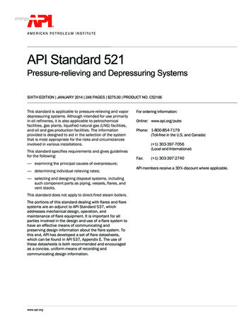
Designed withFig. 26General profile toleranceproperties are thus defined, and when finished,a “Part1” feature with asurface profile associatedto it will appear in theDimXpert manager featurebased tree.In this case, an importantbest practice that shouldbe followed is to add a note to define an all-over general profile tolerance: this can easily beaccomplished by adding a note and clicking onthe “Insert DimXpert general profile tolerance”in the note property manager (Fig. 26).It can be noted that, even though basic dimensions have not been created, all the manufacturing features are completely defined; this isbecause, in model-based processes, downstream applications, such as CAM or inspectionsoftware, can automatically derive this information from the PMI.If needed, it is possible to display the basicdimensions by makingDimXpertmanager as anannotation based tree,and by right clicking on apositional tolerance andselecting “recreate basic dim” from the contextmenu.As shown in Fig. 27, inthis way, basic dimensions will be created withrespect to the datum reference frame.OTHER GD&T TOOLSSOLIDWORKS Model Based definition includes other tools that can be used to dimensiontolerances to tolerance a part in compliance with ASME standards, such as: Manual basic location dimension Manual basic size dimension Moveable datum targetsThese tools can be found in the MBDtab in the command manager.170Fig. 27
Designed withFig. 5Fig. 6Fig. 8By using the concepts learnt inthe previous sections, a 3D Viewmay then be created to show thepart and the table (Fig. 9).Fig. 7Select three datum features, asshown in Fig. 5, and the “All features” option will be selected inthe “Scope” pane. Finally, click onOK in the DimXpertManager.tolerance value explicit on certaindimensions by clicking on a dimension and selecting “Generalwith tolerance” in the dimensionproperty manager (Fig. 7).The model will be dimensionedwith respect to the 3 datums, andif the tolerance status is checked,a green colour will indicate that allthe manufacturing features havebeen defined completely (Fig. 6).It is possible to make a generalInstead of showing explicit tolerances, an alternative approachcould be to insert a general tolerance table in the model. Thiscan be done by choosing Insertg Tables g General tolerance(Fig. 8).172As can be noted in Fig. 6, the auto-dimensioning process is ableto completely define all the manufacturing features, but beingan automated process, it cannotreplace a designer’s experiencein applying GD&T best practices.It is therefore suggested to use acombination of manual and automatic dimensioning to obtain thebest results.Before illustrating an exampleof this approach, all the annotations should be deleted: this caneasily be achieved by deletingthe dimensioning scheme in theDimXpertmanager. It is sufficientto right-click on the part name,then select “delete” from the context menu (Fig. 10). If the message “Do you want to delete allDimXpert features, dimensions,and tolerances?” appears, select“Yes”.
INDEXFOREWORD. PAGE 31. INTRODUCTION. 42. C LASSIFICATION AND INDICATION OF GEOMETRIC TOLERANCES. 93. D IMENSIONING WITH GEOMETRICAL TOLERANCES. 184. THE GD&T LANGUAGE ACCORDING TO THE ISO AND ASME STANDARDS. 22The fundamental ISO 8015 standard.25General geometrical tolerances.29The main differences between the ISO GPS and ASME GD&T standards.355. I NTERDEPENDENCE BETWEEN THE SIZE AND FORM. 37Maximum material condition.37Least material conditions.40Virtual condition.406. DATUMS. 42Indication of the datum features.44Terms and definition in ISO 5459.45Location of a workpiece in a datum reference frame .50Selection of the datum features.51Types of datums.54Datum features referenced at MMR and LMR (Size datum) .57Customised datum reference frame.58Examples of other modifiers used to indicate datums.61Datum targets.63Contacting feature.677. FORM TOLERANCES. 70Straightness 8. ORIENTATION TOLERANCES. 81Parallelism.81Perpendicularity.84Angularity.879. LOCATION TOLERANCES. 91Position tolerances.91Position tolerance applied to median surfaces.95Effects of Specifying the MMR Modifier. 107Concentricity. 109Symmetry. 11010. PROFILE TOLERANCES.116ISO 5458:2018. Pattern and combined geometrical specification. 12311. RUN-OUT TOLERANCES.124Circular run-out. 125Total run-out. 12612. G EOMETRICAL PRODUCT SPECIFICATION FOR NON-RIGID PARTS.130ISO 5458:2018. Multi-level single indicator pattern specification. 134Tolerancing of a cone. 1361. Introduction to SOLIDWORKS MBD.1382. The first step towards MBD: making a 3D model the master by leveragingon modelling dimensions with annotation views.1403. Using DimXpert for coordinate tolerancing.1474. 3D Views.1585. GD&T with DimXpert.1646. Preparing the model and reading manufacturing information.1717. Leveraging on PMI.178INDEX. 182
ANALITIC INDEXAACS (Any Cross Section);61; 109Actual Mating Envelope,AME; 48All around; 14All over; 14Altered default GPSspecification; 25Angularity; 87ASME BSC (Basic); 69ASME Y14.5 standard; 23ASME-ISO comparison; 37Associated feature; 9Associationmethodology; 61Axis methodology; 96BBasic Dimension; 14Bi-directional toleranceof position; 107Bonus; 38CCenterplanes; 54CF symbol, see ContactingfeatureCircular run-out; 124, 125Circularity,see Roundness; 78Classificationof GeometricalTolerances.; 11Coaxiality; 109Collection plane; 17Combined zone; 15Common datum; 55Common Zone, seeCombined Zone; 15, 18Complementarystandard; 24Composite PositionTolerancing; 103Compositeprofile feature; 120Composite toleranceframe; 73Computer Aided Design; 5Concentricity; 109Concentricity ASME; 111Cone tolerancing; 136Contacting feature; 67Coordinate dimensioning; 6Coplanar Surfaces; 121Customised datumreference frame; 58Cylindricity; 79CZ (Combined Zone); 118DDatum; 42Datum axis; 44Datum conical surfaces; 57Datum feature simulator; 47Datum features; 43Datum pattern of holes; 55Datum targets; 63Default principle; 28Degrees of freedom of aworkpiece; 50Derived feature; 9Derived median line; 74DRF (Datum ReferenceFrame); 50Duality principle; 28, 35DV (distance variable; 56EEnvelope requirement; 32Extracted derivedfeature; 9FFeature of Size; 19Feature-Relating ToleranceZone Framework; 111Filter specification; 79Fixed fastener formula; 100Flatness; 74Flatness (ASME); 77Floating fastener formula;99Form tolerances; 10; 70Free State condition; 130Functional dimensioning; 4Functional gauge; 68, 113Functional gaugingtechniques; 74Functional limits; 28Fundamental standard; 24GGage; 33, 113Gauges; 33Gaussian (G) method; 61Gaussian circle; 72Gaussian dimensioningconcept; 35Gaussian interpolation; 72GD&T; 5; 22General geometricaltolerances; 29General s
lerancing (GD&T) languages are the most powerful tools available to link the perfect geometrical world of models and drawings to the imperfect world of manufactured parts and assemblies. This book is intended for designers, process engineers and CMM operators, and it has the main purpose of