Transcription
Computer-Aided Design of ASICsConcept to SiliconVictor P. NelsonVLSI Design & Test Seminar11/05/2011
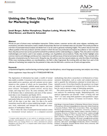
IC Design Flow
Digital ASIC Design -EndDesignSynthesisDFT/BIST& ATPGGate-LevelNetlistFull-custom ICTest vectorsStandard Cell IC& FPGA/CPLDDRC & stPhysicalLayoutMap/Place/RouteVerify Function& TimingBack-EndDesignVerifyTimingIC Mask Data/FPGA Configuration File
Mentor Graphics Analog/Mixed-SignalIC Nanometer Design Flow
ASIC CAD tools available in ECE Modeling and Simulation Questa ADMS Questa Modelsim Eldo ADiT (Mentor Graphics) Verilog-XL, NC Verilog, Spectre (Cadence) Design Synthesis (digital) Leonardo Spectrum (Mentor Graphics) Design Compiler (Synopsys), RTL Compiler (Cadence) Design for Test and Automatic Test Pattern Generation Tessent DFT Advisor, Fastscan, SoCScan (Mentor Graphics) Schematic Capture & Design Integration Design Architect-IC (Mentor Graphics) Design Framework II (DFII) - Composer (Cadence) Physical Layout IC Station (Mentor Graphics) SOC Encounter, Virtuoso (Cadence) Design Verification Calibre DRC, LVS, PEX (Mentor Graphics) Diva, Assura (Cadence)
Mentor Graphics ASIC Design Kit (ADK)We also have ADK’s for Cadence tools for several technologies Technology files & standard cell libraries AMI: ami12, ami05 (1.2, 0.5 μm) TSMC: tsmc035, tsmc025, tsmc018 (0.35, 0.25**, 0.18 μm) **also have VT Cadence lib Current MOSIS Instructional: IBM 180nm CMOS (7RF), ON Semi 0.5um CMOS Current MOSIS Unfunded Research: IBM 130nm CMOS (8RF), 130nm SiGE BiCMOS(8HP) IC flow & DFT tool support files: Simulation models VHDL/Verilog/Mixed-Signal models (Modelsim SE/Questa ADMS)Analog (SPICE) models (Eldo, ADiT)*Post-layout timing (Mach TA) * obsolete: Mach TA replaced by ADiT*Digital schematic (Quicksim II, Quicksim Pro) * obsolete: HDL or Eldo now usedStandard cell synthesis libraries (LeonardoSpectrum)Design for test & ATPG libraries (DFT Advisor, Fastscan)Schematic capture (Design Architect-IC)IC physical design (standard cell & custom) Standard cell models, symbols, layouts (IC Station) Design rule check, layout vs schematic, parameter extraction (Calibre)
Xilinx/Altera FPGA/CPLD Design Tools Simulate designs in Modelsim Behavioral models (VHDL,Verilog) Synthesized netlists (VHDL, Verilog) Requires “primitives” library for the target technology Synthesize netlist from behavioral model Leonardo (Levels 1,2,3) has libraries for most FPGAs (ASIC-only license currently installed) Xilinx ISE and Altera Quartus II have own synthesis tools Vendor tools for back-end design Map, place, route, configure device, timing analysis, generate timing models Xilinx Integrated Software Environment (ISE) Altera Quartus II & Max Plus2 Higher level tools for system design & management Mentor Graphics FPGA Advantage Xilinx Platform Studio : SoC design, IP management, HW/SW codesign
Automated ASIC Design FlowSource: CMOS IC Layout, Dan CleinStd Cell ASICFull Custom IC
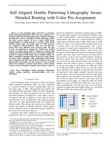
Behavioral Design & L-AMSVerilog-AMSCreate Behavioral/RTLHDL Model(s)Simulate to VerifyFunctionalityLeonardo Spectrum,Synopsys Design Compiler,Xilinx ISE (digital)Questa ADMS(analog/mixed signal)SynthesizeCircuitSimulate to VerifyFunction/TimingTechnology-Specific Netlist& Timing to Back-End ToolsTechnologyLibrariesDesign ConstraintsVITALLibrary
Questa ADMS (replaced ADVance MS) Four simulation engines integrated for SoC designs Questa – mixed signal simulation (VHDL-AMS, Verilog-AMS)QuestaSim (Modelsim) – VHDL/Verilog/SystemC digital simulationEldo/Eldo RF – analog (SPICE) simulation (replaced Accusim)ADiT – accelerated transistor-level (Fast-SPICE) simulation (replaced Mach TA) Engines, languages, standards can be mixed in a simulation IEEE 1497 Standard Delay File Format (SDF)IEEE 1076.1 VHDL-AMSIEEE 1076 VHDLIEEE 1364 VerilogIEEE 1800 SystemVerilogIEEE 1666 SystemCAccellera standard Verilog-AMS LanguageSPICE Eldo, HSPICE, and Spectre dialects.
Questa ADMSAnalog, Digital, Mixed-Signal SimulationVHDL,Verilog,VHDL-AMS, Verilog-AMS,SPICE NetlistsWorkingLibrarySimulationSetupEldo,Eldo RFAnalog(SPICE)ADiTDesign 1Design 2VITALSPICEXilinxmodels SIMPRIMSIEEE 1164Questa ADMSEZwaveView liModelsimDigital(VHDL,Verilog)Mixed Signal(VHDL-AMS,Verilog-AMS)
Questa ADMS : mixed-signal simulationA/D converterdigitalanalogVHDL-AMSdigital netsanalog nets
Questa ADMS: mixed Verilog-SPICEVerilog top(test bench)SPICEsubcircuit
Automated Synthesis withLeonardoSpectrum/Synopsys Design erilogBehavioral/RTL ModelsLeonardo Spectrum(Level 3)Synopsys Design Compiler& Design Vision (GUI)DesignConstraintsDWMentor ADK:AMI 0.5, 1.2TechnologyTSMC 0.35, 0.25SpecificCadence ADKsNetlistTSMC 0.25OthersSynopsysVHDL, Verilog, SDF,“DesignWare”ModulesEDIF, XNFLeonardo Spectrum:Level 1 – FPGALevel 2 – FPGA TimingLevel 3 – ASIC FPGA(we have Level 3 ASIC only)
Leonardo – ASIC Synthesis FlowSynthesizegeneric gates& modulesRead &check HDLMap to technologycells & optimizeWrite netlist,SDF, reports
Sample LeonardoSpectrum synthesis script load library /linux apps/ADK3.1/technology/leonardo/tsmc025 typ analyze "./src/mux.vhd" "./src/shiftreg.vhd" "./src/alu.vhd" "./src/dcontrol.vhd" "./src/divider.vhd“elaborateclock cycle 2 CLOCKoptimize -hierarchy preserveoptimize timing -through C/reg State(2)/Qwrite divider 0.vhdwrite divider 0.vwrite divider 0.sdfreport area div area.rpt -cell usage –hierarchyreport delay div delay.rptreport delay -longest path -to Q* mod6 outdelay.rptreport delay -longest path -from [list I* L Cbar] mod6 indelay.rpt
Post-synthesis simulation ofsynthesized netlist Verify that synthesized netlist matches behavioral model Create library of std cell simulation primitives: vlib adk vcom ADK/technology/adk.vhd vcom ADK/technology/adk comp.vhdVITAL modelsof ADK std cells Insert library/package declaration into netlistlibrary adk;use adk.adk components.all; Simulate in Modelsim, using “do file” or test bench frombehavioral simulation results should match Simulate netlist with synthesize-produced SDF file to studytiming (delays, constraints, etc.)
Post-synthesis timing analysis Synthesis tools generate SDF (std. delay format) file with technology-specific, VITAL-compliant timing parameters (from cell library)(CELLTYPE "dffr")(INSTANCE Q 0 EXMPLR EXMPLR)(DELAY(ABSOLUTE(PORT D (::0.00) (::0.00))(PORT CLK (::0.00) (::0.00))(PORT R (::0.00) (::0.00))(IOPATH CLK Q (::0.40) (::0.47))(IOPATH R Q (::0.00) (::0.55))(IOPATH CLK QB (::0.45) (::0.36))(IOPATH R QB (::0.53) (::0.00))))(TIMINGCHECK(SETUP D (posedge CLK) (0.47))(HOLD D (posedge CLK) (-0.06))))Delays lumped at pinsPath delays(min:typ:max)Clock constraints
VITAL Std. Cell Model (1)library IEEE; use IEEE.STD LOGIC 1164.all;use IEEE.VITAL Primitives.all; use IEEE.VITAL Timing.all;entity and02 isgeneric (tipd A0 : VitalDelayType01Z : VitalZeroDelay01Z;tipd A1 : VitalDelayType01Z : VitalZeroDelay01Z;tpd A0 Y : VitalDelayType01Z : VitalZeroDelay01Z;tpd A1 Y : VitalDelayType01Z : VitalZeroDelay01Z);port (A0 : in STD LOGIC;A1 : in STD LOGIC;Y : out STD LOGIC);attribute VITAL LEVEL0 of and02 : entity is TRUE;end and02;Delays fromSDF file
VITAL Std. Cell Model (2)architecture and02 arch of and02 isattribute VITAL LEVEL1 of and02 arch : architecture is TRUE;signal A0 ipd : STD LOGIC : 'X';signal A1 ipd : STD LOGIC : 'X';beginWireDelay : BlockbeginDetermine inputVitalWireDelay (A0 ipd, A0, tipd A0);pin delays (if any)VitalWireDelay (A1 ipd, A1, tipd A1);end Block;VitalBehavior : Process (A0 ipd, A1 ipd)VARIABLE INT RES 0 : STD LOGIC : 'X';VARIABLE GlitchData Y : VitalGlitchDataType;begin-- FUNCTIONALITY SECTION -INT RES 0 : VitalAnd2 (A0 ipd, A1 ipd);Ideal (zero-delay)AND function
VITAL Std. Cell Model (3)-PATH DELAY SECTION-VitalPathDelay01Z (-- VITAL Function CallOutSignal Y,OutSignalName "Y",Determine delay alongOutTemp INT RES 0,each input-output pathPaths (0 ( InputChangeTime A0 ipd'LAST EVENT,PathDelay tpd A0 Y,PathCondition TRUE),1 ( InputChangeTime A1 ipd'LAST EVENT,PathDelay tpd A1 Y,PathCondition TRUE)),GlitchData GlitchData Y,Mode OnDetect,MsgOn TRUE, Xon TRUE,MsgSeverity WARNING
Design for test & test generation Consider test during initial design phase Test development more difficult after design frozen Basic steps: Design for test (DFT) – insert test points, scan chains, etc. toimprove testability Insert built-in self-test (BIST) circuits Generate test patterns (ATPG) Determine fault coverage (Fault Simulation) Mentor Graphics Tessent Silicon Test tools support the above
Tesssent – Test & Yield Analysis ToolsTessent FastScanTessent SoCScan& DFTAdvisor
Mentor Graphics “Tessent” Products Tessent Fastscan – ATPG and Fault Simulation Fault models supported: stuck-at, IDDQ, transition, path delay andbridge. Tessent SoC Scan (insert hierarchical scan) Absorbs functionality of older DFTAdvisor Tessent DFTAdvisor – insert full/partial scan and test ckts Also: Tessent TestKompress (ATPG for scan tests)Tessent Boundary Scan (IEEE 1149.1)Tessent LogicBISTTessent MemoryBISTTessent Diagnosis (failure diagnosis)Tessent YieldInsight (statistical analysis of diagnosis data to findsystematic yield limiters)
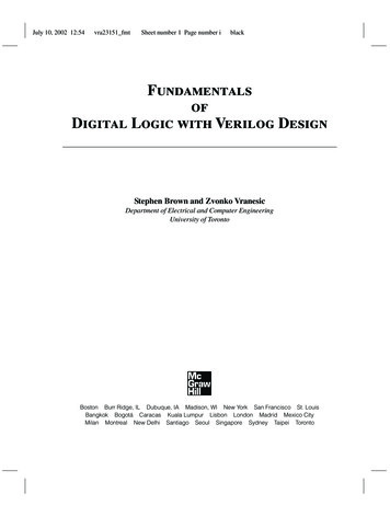
ASIC DFT FlowSynthesized VHDL/Verilog NetlistATPG LibraryTessentDFTAdvisorInsert InternalScan CircuitryVHDL/VerilogNetlist WithScan ElementsTessentFastscanGenerate/VerifyTest VectorsTest Pattern Fileadk.atpg
DFT & test design flowMemory& LogicBISTBoundaryScanInternalScan DesignATPG
DFTadvisor/FastScan Design Flowcount4.vhdLeonardoDFT/ATPGLibrary:count4 0.vhdcount4.vcount4 scan.vadk.atpgSource: FlexTest Manual
Example DFTadvisor script (Chan Hao) dftadvisor –verilog count4.v –lib ADK/technology/adk.atpg analyze control signals -auto fix set scan type mux Scan set system mode dft setup scan identification full scan run //here you can determine how many scan chains you want to create insert test logic -scan on -number 3 //another way to create scan chains by giving maximum scan chain length //insert test logic -scan on -max length 30 write netlist s1423 scan.v -verilog -replace //write dofile and procedure file for fastscan write atpg setup s1423 scan -procfile -replace exit
count4 – without scan design
count4 – scan inserted by DFTadvisorScan ControlScan FFScan In
ATPG with FastScan (full-scan circuit) Invoke: fastscan –verilog count4.v –lib ADK/technology/adk.atpg Generate test pattern file in FastScan: dofile count4 scan.dofile (defines scan path & procedure) ** set system mode atpg create patterns –auto(generate test patterns) save patterns** “count4 scan.dofile” was created by DFTadvisor
Test file: scan chain definition andload/unload proceduresscan group "grp1" scan chain "chain1" scan in "/scan in1";scan out "/output[3]";length 4;end;procedure shift "grp1 load shift" force sci "chain1" 0;force "/clock" 1 20;force "/clock" 0 30;period 40;end;procedure shift "grp1 unload shift" measure sco "chain1" 10;force "/clock" 1 20;force "/clock" 0 30;period 40;end;procedure load "grp1 load" force "/clear" 0 0;force "/clock" 0 0;force "/scan en" 1 0;apply "grp1 load shift" 4 40;end;procedure unload "grp1 unload" force "/clear" 0 0;force "/clock" 0 0;force "/scan en" 1 0;apply "grp1 unload shift" 4 40;end;end;
Generated scan-based test// send a pattern through the scan chainCHAIN TEST pattern 0;apply "grp1 load" 0 (use grp1 load procedure)chain "chain1" "0011"; (pattern to scan in)end;apply "grp1 unload" 1 (use grp1 unload procedure)chain "chain1" "1100"; (pattern scanned out)end;end;// one of 14 patterns for the counter circuitpattern 0;(pattern #)apply "grp1 load" 0 (load scan chain)chain "chain1" "1000"; (scan-in pattern)end;force "PI" "00110" 1;(PI pattern)measure "PO" "0010" 2;(expected POs)pulse "/clock" 3;(normal op. cycle)apply "grp1 unload" 4 (read scan chain)chain "chain1" "0110"; (expected pattern)end;
ASIC Physical Design (Standard Cell)(can also do full custom layout)Component-Level Netlist (EDDM format)Std. CellLayoutsFloorplanChip/BlockLibrariesMentor Graphics“IC Station”(Linux cmd: adk ic)ICblocksProcess DataPlace & RouteStd. CellsDesign RulesGenerateMask DataDesign RuleCheckCalibreIC Mask DataBackannotateSchematicCalibreLayout vs.SchematicCheckCalibreMach TA/Eldo Simulation Model
Cell-Based ICI/O pads
Cell-Based Block
Basic standardCell layoutSource: Weste “CMOS VLSI Design”
1.Preparation for LayoutUse Design Architect-IC to convert Verilog netlist to MentorGraphics EDDM netlist format Invoke Design Architect-IC (adk daic)On menu bar, select File ImportVerilog Netlist file: count4.v (theVerilog netlist)Output directory: count4 (for the EDDM netlist)Mapping file ADK/technology/adk map.vmpOpen the generated schematic for viewing2. Click Schematic in DA-IC paletteSelect schematic in directory named above (see next slide)Click Update LVS in the schematic palette to create a netlist to be used later by“Calibre”Create design viewpoints for ICstation tools3. adk dve count4 –t tsmc035(V.P’s: layout, lvs, sdl, tsmc035)Can also create gate/transistor schematics directly in DA-IC usingcomponents from the ADK library
DA-IC generated schematic
Eldo simulation from DA-IC Run simulations from within DA-IC Eldo, Questa ADMS, ADiT DA-IC “netlister” creates a circuit model from the schematic SPICE model for Eldo & ADiT Eldo analyses, forces, probes, etc. same as SPICE View results in EZwave
SPICE “circuit” file generated by DA-ICFrom ADKlibraryForce values (created interactively)SPICE netlist for modulo7 counter
Automated Layout Design Flow
IC Station create cell dialog box(Linux command: adk ic) ADK/technology/icUse schematicto drive layout
Auto-”floorplan” the blockplace & route autofp
Auto-place the std cellsAutoplc StdCel
Auto-place ports (signal connections on cell boundaries)Autoplc Ports
AutoRoute all nets(hand-route any unrouted “overflows”)Then: Add Port Text to copy port names from schematic – for Calibre
Layout design rule check (DRC) Technology-specific design rules specify minimum sizes,spacing, etc. of features to ensure reliable fabrication Design rules file specified at startupEx. tsmc035.rules From main palette, select ICrules Click Check and then OK in prompt box(optionally select a specific area to check) Rules checked in numeric order
Common errors detected by DRC To fix, click on First in palette to highlight first error Error is highlighted in the layout Click View to zoom in to the error (see next) Example: DRC9 2: Metal2 spacing 3L Fix by drawing a rectangle of metal2 to fill in the gap betweencontacts that should be connected Click Next to go to next error, until all are fixedNOTE: MOSIS will not fabricate a chip with DRC errors –they perform their own DRC.
Sample error: DRC9 2 metal2 spacing 3LDrawrectangleof metal2to fill gapIt also called contact-to-contact metal 2 spacing DRC9 2 error
Layout vs schematic check usingCalibre Interactive LVS Compare extracted transistor-level netlist against netlist savedin DA-IC From ICstation menu: Calibre Run LVS In popup, Calibre location: MGC HOME/./Calibre Rules: ADK/technology/ic/process/tsmc035.calibre.rules Input: count4.src.net (previously created in DA-IC) H-cells: ADK/technology/adk.hcell (hierarchical cells) Extracted file: count4.lay.net
Post-layout parameter extraction viaCalibre Interactive PEX Extract Spice netlist, including parasitic RC Simulate in Eldo or MachTA ICstation menu: Calibre Run PEX Options are similar to Calibre LVS Extraction options: lumped C coupling cap’s distributed RC distributed RC coupling cap’s Output file: count4.pex.netlist
Post-layout simulation: ADiT Fast-SPICE simulator Analog & mixed-signal 10X to 100X faster thanother SPICE simulators Integrated with Questa Examples: MGC AMS HOME/examples/adit/
Top level layout design flow** Create a symbol for each core block (adk daic) Create a chip-level schematic from core blocks and pads(adk daic) Generate design viewpoints (adk dve) Create a layout cell for the chip (adk ic) Place core logic blocks from the schematicGenerate a pad frameMove/alter core blocks to simplify routingRoute pads to core blocksDesign rule check & fix problems Generate mask data** Refer to on-line tutorials by Yan/Xu and by Dixit/Poladia
Chip-level schematic (1) Generate a symbol for each “core” logic block In DA-IC, open the schematic (eg. modulo7) Select: Miscellaneous Generate Symbol Add “phy comp” property to the symbol Select the body of the symbol From the popup menu: Properties Add Enter property name: phy comp Enter property value: mod7b(layout cell name for the block created in IC Station) Check & saveExample on next slide
Symbol with phy comp property(associate layout with symbol)Layoutcell is“mod7b”for logicschematic“modulo7”
Chip-level schematic (2) In DA-IC, create a schematic for the chip Instantiate core blocks Menu pallete: Add Instance Select and place generated symbol Add pads from ADK Library Std. Cells Pads tsmc035 : In, Out,BiDir, VDD, GND Wire pads to logic blocks and connectors Assign pin numbers, if known Change pad instance name to PINdd (dd 2-digit pin #) Check & save Create design viewpoints with adk dveExample on next slide
Top-level schematic for “modulo7” chipVDD/GNDPadsHierarchicalconnectorson “Pad” pinsInstancename PINxx(chip pin #)Core blockWire block I/O pinsto pad signal pins
Assigning PAD pin numbersChange instance name property on pads to PINxxxx 2-digit pin number (01 – 40 for Tiny Chip package)Place pad onchip pin 01Defaultinstancenames
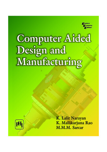
Top-level chip layout Start IC Station (adk ic) & create a new layout cell enter cell name logic source is “layout” viewpoint of chip schematic same library, process file, rules file, and options as standard cell layout Open the schematic ADK Edit menu: Logic Source Open In the schematic, select all core cells (but not pads) Place the cells: Place Inst Generate the pad frame Top menu bar: ADK Generate Padframe tsmc035(Only: AMI 1.2um, AMI 0.5um,TSMC 0.35um)
Chip layout (2) Move, rotate, flip core logic cells as desired to make routingeasier DO NOT EDIT OR MOVE PAD CELLS Autoroute all connections Select autoroute all on P&R menu Click “options” on prompt bar, and unselect “Expand Channels”(prevents pads from being moved) Add missing VDD/GND wires, if necessary Autorouter might only create 1 VDD/GND wire, even if multipleVDD/GND pads Manually add others: Objects Add Path VDD/GND net width 50 VDD/GND net vias 6x6 (copy an existing via)
Modulo-7 counter in pad frame
IEEE 1497 Standard Delay File Format (SDF) IEEE 1076.1 VHDL -AMS IEEE 1076 VHDL IEEE 1364 Verilog IEEE 1800 SystemVerilog IEEE 1666 SystemC Accellera standard Veri