Transcription
Criteria for Detention Facility Design0CRITERIA FOR DETENTIONFACILITY DESIGNBureau of Water & Sewer OperationsRevised November 19, 2012For more information contact:718-595-4325or sewerinfo@dep.nyc.gov
ContentsCriteria.1I. Detention Facilities with a variable outflow .3II. Detention Facilities within an approximately constant outflow .4III.Weighted effective runoff coefficient for series detention systems .5IV.Maximum storage depth with an orifice tube outlet .6General .8Example 1.9Example 2.10Example 3.11Example 4.12Stormflow Calculations .13Sample 1 .14Sample 2 .15
Criteria for Detention Facility Design1CriteriaThe following procedure is to be used to compute the total site developed storm flow in cubic feetper second (cfs), “QDEV”, the Allowable Flow in cfs, “QALL”, the detention facility maximumrelease rate in cfs, “QDRR”, the required detention facility volume in cubic feet (ft3), “VR”, and thedetention facility maximum storage depth in feet, (ft.), “SD”. It is used for house connectionproposals and site connection proposals, for storm flow generated totally within the site, to bedetained within the site, and not receiving any street flow.The detention facility is designed to provide the maximum volume required for the storm with a 10year (yr.) return frequency. Porous open bottom detention facilities must be located a minimum of3 ft. above the ground water table to prevent possible ground water infiltration into the sewersystem and 10 ft. minimum (and/or per Construction Code) away from Building Foundation. Theuse of open bottom detention facilities requires the submission of boring logs to establish groundwater levels and soil permeability when infiltration credit is applicable.The method described below is based on an article entitled," A simple method of retention basindesign", by Glen Yrjanainen and Alan W. Warren, which appeared in Water and Sewage Works,December 1973, and "Storm Water Detention for Drainage, Water Quality, and CSOManagement", by Peter Stahre and Ben Urbonas, published by Prentice Hall, 1990.Detention storage volume is computed by calculating the difference between the inflow andoutflow hydrographs, by the basic equation:VR where: t(QIN – QOUT) 60 dtt0VR the required detention storage volume in ft3t0 the beginning of the time of storage in minutes (min.)t the total time that storage is required in min.QIN the average inflow rate to the facility in cfsQOUT the average outflow rate from the facility in cfs
Criteria for Detention Facility Design2The average inflow rate in cfs is computed based on the, “Rational Method”, by the equation:where:QINCWTiATQIN CWTiAT the average inflow rate in cfs during the rainfall event the weighted runoff coefficient for the tributary area the average rainfall intensity in inches per hour (in/hr) for the event the area tributary to the detention facility in acres (ac.)The weighted runoff coefficient for an area tributary to a detention facility is computed by theequation:where:CWTC1A1C2A2AtCWT (C1A1 C2A2 etc.)/ At the weighted runoff coefficient for the tributary area the runoff coefficient for the area classified as roof the area classified as roof in square feet (ft2) the runoff coefficient for the area classified as paved the area classified as paved in ft2 the area tributary to the detention facility in ft2The average rainfall intensity in in/hr, i, is computed for the storm with a 10 yr. return frequencyby the equation:where:i10 140/(t 15) theaveragerainfallintensity in in/hr for the storm with a 10 yr. returni10frequency t the duration of a rainfall event in min. for the storm with a 10 yr. returnfrequencyThe “Rational Method”, assumes a uniform block rainfall distribution over the entire tributary areafor the duration of the rainfall event, that the runoff hydrograph has the same shape with respect totime as the rainfall hyetograph, and that the use of a weighted runoff coefficient for the tributaryarea is valid. For urban areas of 400 ac. or less these assumptions are appropriate.Under the new rule for stormwater management for discharge to a combined sewer system themaximum release rate in cfs, QRR, to which the site stormwater flow rate to the combined sewerwill be restricted shall be the greater of 0.25 cfs or 10% of the Allowable Flow. If the AllowableFlow is less than 0.25 cfs, the site stormwater release rate to the combined sewer shall be theAllowable Flow. For discharge to a separate storm sewer system the maximum release rate in cfs,QRR, to which the site stormwater flow rate to the storm sewer will be restricted will be theAllowable Flow. The Allowable Flow in cfs, QALL , is computed in accordance with the, “RationalMethod”, by the equation:
Criteria for Detention Facility Designwhere:QALLCDPiDPADP3QALL CDPiDP ADP/43,560 the Allowable Flow rate in cfs the runoff coefficient for the site, from the drainage plan the most upstream rainfall intensity in in/hr, from the drainage plan the area of the site tributary to the sewer in ft2, as per the drainage planThe maximum release rate in cfs from a detention facility, QDRR, is not always the same as themaximum release rate in cfs to which the site stormwater flow rate will be restricted, QRR. In caseswhere a detention facility discharges to another facility in series, the maximum release rate fromthe upstream facility may be greater than the Allowable Flow and or the maximum release ratefrom the site, QRR. The maximum release rate in cfs from a detention facility which is connected toa sewer, QDRR, will depend on whether the connection is to a combined sewer or to a separatestorm sewer, the number of connections proposed, if any stormwater flow will be dischargedunrestricted, if any constant and continuous stormwater recycling and reuse is proposed, or if anyinfiltration credit is proposed. Constant and continuous stormwater recycling and reuse andinfiltration credit reduce the required detention volume, but do not increase the maximum releaserate to the sewer system, QRR. For a site where the total site stormwater discharges through aconnection with no unrestricted discharge the maximum release rate from the detention facility,QDRR, will be equal to the maximum stormwater release rate from the site, QRR.I.Detention Facilities with a variable outflowFor a detention facility where the outflow is controlled by means of an outlet orifice tube, subjectto a head which increases as the depth of storage increases, in a storage facility with anapproximately uniform area with respect to storage height, and for roof detention by means ofcontrolled flow roof drains, the average flow rate out of the detention facility is approximately 2/3of the maximum outflow rate. The following procedure is used to compute the maximum requireddetention storage volume in ft3:1. Compute the duration of the storm in minutes with a 10 yr. return frequency, tV, which requiresthe maximum detention volume with outflow controlled by an orifice or by controlled flowroof drains, by the equation:where: 0.27(CWT At /QDRR)0.5 – 15 the duration of the storm in min. with a 10 yr. return frequency requiring themaximum detention volume with a variable outflow the weighted runoff coefficient for the area tributary to the detention facility the area tributary to the detention facility in ft2 the detention facility maximum release rate in cfstVtVCWTAtQDRR
Criteria for Detention Facility Design42. Compute the maximum required detention volume in ft3 with outflow controlled by an orificetube or by controlled flow roof drains, VV, by the equation:where:VV [0.19CWTAt /(tV 15) – 40QDRR] tVVV the maximum required detention volume in ft3 with a variable outflowCWT the weighted runoff coefficient for the area tributary to the detention facility2At the area tributary to the detention facility in fttV the duration of the storm in min., with a 10 yr. return frequency, requiringthe maximum detention volume with a variable outflowQDRR the detention facility maximum release rate in cfs3. For roof detention compute the duration of the storm in minutes with a 10 yr. return frequency,tV, which requires the maximum detention volume, and compute the maximum requireddetention volume in ft3 with outflow controlled by controlled flow roof drains, VV, with adetention facility maximum release rate in cfs, QDRR, as in I-1 through I-2 above. Confirm thatthe detention volume provided on the controlled flow roof, based on the slopes and geometryof the roof, is equal to or greater than the volume required, VV, and that the actual release ratefrom the roof does not exceed the proposed maximum release rate in cfs for the roof, QDRR,following the procedure detailed in the DEP “Guidelines for the Design and Construction ofStormwater Management Systems”.II.Detention Facilities within an approximately constant outflowFor a detention facility where the outflow is approximately constant, as by the use of a pumpcharacterized by a steep curve operating over a narrow head range, or by the use of an orifice tubesubject to an approximately constant head, the average flow rate out of the detention facility isapproximately 95% of the maximum outflow rate. The following procedure is used to compute therequired detention storage volume in ft3.1. Compute the duration of the storm in min. with a 10 yr. return frequency, tC, which requires themaximum detention volume with an approximately constant outflow, by the equation:where: 0.23(CWT At /QDRR) 0.5 – 15 the duration of the storm in min., with a 10 yr. return frequency, requiringthe maximum detention volume with an approximately constant outflow the weighted runoff coefficient for the area tributary to the detention facility the area tributary to the detention facility in ft2 the detention facility maximum release rate in cfstCtCCWTAtQDRR
Criteria for Detention Facility Design52. Compute the maximum required detention volume in ft3 with an approximately constantoutflow, VC, by the equation:where:VCCWTAttCQDRRIII.VC [0.19CWT At /(tC 15) – 57QDRR] tC the maximum required detention volume with an approximately constantoutflow the weighted runoff coefficient for the area tributary to the detention facility the area tributary to the detention facility in ft2 the duration of the storm in min., with a 10 yr. return frequency, requiringthe maximum detention volume with an approximately constant outflow the detention facility maximum release rate in cfsWeighted effective runoff coefficient for series detention systems1. A. When the flow from a roof which has been restricted by controlled flow roof drains isdischarged to a subsurface detention facility, the weighted effective weighted runoffcoefficient for the roof, CWE, is based on the average rainfall intensity in in/hr, i10, forthe duration in min. of the storm with a 10 yr. return frequency, as computed under I-1,tV, for which the roof detention volume in ft3, VV, was computed. Compute theweighted effective runoff coefficient for the roof with runoff restricted by controlledflow roof drains, CWE, by the equation:where:B.CWE 311QDRR(tV 15)/ AtCWE the weighted effective weighted runoff coefficient for the roof withrunoff restricted by controlled flow roof drainsQDRR the maximum release rate from the roof in cfstV the duration in min of the rainfall event for which the roof detentionvolume was computedAt the area of the roof in ft2 tributary to the roof detention311 43,560 ft2 per ac./140Use this effective weighted runoff coefficient for the roof with runoff restricted bycontrolled flow roof drains, CWE, to compute the weighted runoff coefficient for thearea tributary to the sub- surface detention facility, CWT, to which this restricted roofwill discharge, as on page 2 above. Compute the maximum required detention volumein ft3, VV as in I-1 through I-2, or VC as in II-1 through II-2.
Criteria for Detention Facility Design2. A.When the flow from an area which has been restricted by detention and a controlledflow device is discharged to a subsurface detention facility, the weighted effectiveweighted runoff coefficient for the area which has been restricted by detention and acontrolled flow device, CWE, is based on the average rainfall intensity in in/hr, i10, forthe duration in min. of the storm with a 10 yr. return frequency, as computed under I1 tV, for which the detention volume in ft3, VV, was computed. Compute the weightedeffective runoff coefficient for the area with runoff restricted by detention and acontrolled flow device, by the equation:where:CWE 311QDRR(tV 15)/ AtCWE the weighted effective runoff coefficient for the area with runoffrestricted by detention and a controlled flow deviceQDRR the maximum release rate in cfs from the area with runoffrestricted by detention and a controlled flow device theduration in min of the rainfall event for which the detentiontVvolume was computedAt the area of the roof in ft2 tributary to the roof detention311 43,560 ft2 per ac./140B.Use this weighted effective runoff coefficient for the area with runoff restricted bydetention and a controlled flow device, CWE, to compute the weighted runoff coefficient for thearea tributary to the subsurface detention facility, CWT, to which this area with runoff restricted bydetention and a controlled flow device will discharge, as on page 2 above. Compute the maximumrequired detention volume in ft3, VV as in I-1 through I-2, or VC as in II-1 through II-2.IV.6Maximum storage depth with an orifice tube outletAn orifice tube outlet may be used to restrict the flow rate from detention facilities to themaximum release rate in cfs, QDRR. Flow through an orifice tube outlet in cfs is a function of thecoefficient of discharge for the type of orifice tube, the cross sectional area of the orifice tube inft2, the square root of twice the acceleration due to gravity, and the square root of the head in ft. onthe orifice tube outlet, measured from the center of the tube.Two types of orifice tube outlet are used. To maximize the head, or to minimize the orifice tubediameter (dia.), use a Re-entrant orifice tube outlet, where the tube projects into the outlet controlstructure one dia. To minimize the head, or to maximize the orifice tube dia., use a Flush orificetube outlet, where the tube is flush with the wall of the outlet control structure. The maximumlength of the orifice tube outlet is 2 ft., after which it must enlarge by at least one dia. size.
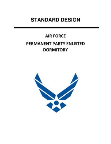
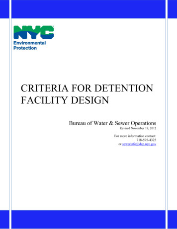
Criteria for Detention Facility Design7The minimum requirements for an outlet control structure are shown on “SAMPLE 1 OUTLETCONTROL STRUCTURE WITH REENTRANT ORIFICE TUBE” and on “SAMPLE 2 FLUSHOUTLET CONTROL STRUCTURE WITH FLUSH ORIFICE TUBE”, on pages 14 and 15. Themaximum required detention volume in ft3, VR, must be provided between the elevation of theinvert of the orifice tube outlet, and the elevation of the maximum storage depth in ft., SD. Toavoid clogging and maximize the subsurface storage depth, the minimum size orifice tube outletused is two inches (in.) in dia. DEP requires a Declaration of Maintenance, recorded as a DeedRestriction against the property when the dia. of the orifice tube outlet is less than three in.Flow through an orifice tube in cfs is computed by the equation:where:QDRR CD AO (2g h)0.5QDRR the detention facility maximum release rate in cfsCD the coefficient of discharge for the type of orifice tube outlet, Re -entrant orFlushAO the area of the orifice tube in ft2g the acceleration due to gravity, 32.2 ft/sec2h the maximum head in ft. on the orifice tube outlet, measured from thecenter of the orifice tubeand the maximum storage depth in ft., SD, is equal to the maximum head in ft., h, plus one half ofthe dia. of the orifice tube outlet in ft.1. Compute the maximum storage depth in ft. of a detention facility with a Re-entrant orificetube outlet, SDR, with a CD of 0.52, by the equation:where:SDRQDRRdOSDR 1,930(QDRR)2 /(dO)4 dO /24 the maximum storage depth in ft. for a Re-entrant orifice tube outlet the detention facility maximum release rate in cfs the nominal dia. of the orifice tube outlet in in.2. Compute the maximum storage depth in ft. of a detention facility with a Flush orifice tubeoutlet, SDF, with a CD of 0.61, by the equation:where:SDFQDRRdOSDF 1,400(QDRR)2 /(dO) 4 dO /24 the maximum storage depth in ft. for a Flush orifice tube the detention facility maximum release rate in cfs the nominal dia. of the orifice tube outlet in in.
Criteria for Detention Facility DesignGeneralThere are many ways to restrict the developed site storm flow to the maximum release rate in cfs,QDRR, and of providing the required detention volume in ft3, VR. Whatever means is used, volumeprovided below the elevation of the invert of the orifice tube outlet, or above the elevation of themaximum storage depth, SD, is not counted in computing the volume provided. Volume has beenprovided in poured in place reinforced concrete tanks, pre cast solid vertical reinforced concreterings, reinforced concrete and corrugated metal pipes, steel and fiberglass tanks, gravel beds,slotted vertical reinforced concrete rings and gravel beds, perforated pipe and gravel beds, stormwater storage modules, solid HDPE pipes, perforated HDPE pipes and gravel beds, infiltrator typesystems, synthetic turf athletic field under drain systems, above ground ponds, rain gardens, andrain water reuse or recycling systems.8
Criteria for Detention Facility DesignExample 1A site in the Bronx connecting to a pre-1964 15 in. Drainage Plan combined sewer, where only aportion the site is allowable to the sewer. All the storm flow discharges through the subsurfacedetention facility.Given:AreaRoofPavedGrassCWTQALLQDEVQDRR 93,200 ft2 29,000 ft2 @ 0.95 runoff coefficient 48,000 ft2 @ 0.85 runoff coefficient 16,200 ft2 @ 0.20 runoff coefficient [(29,000)0.95 (48,000)0.85 (16,200)0.20]/93,200 0.768 132(100)/24,800 0.53 cfs [(29,000)0.95 (48,000)0.85 (16,200)0.20]/7,320 9.78 cfs. 0.25 cfsA. Outflow will be controlled by an orifice tube and will vary with the depth of storage.tV 0.27[(0.768)(93,200)/0.25]0.5 – 15 129.5 min.VV [(0.19)(0.768)(93,200)/(129.5 15) – 40(0.25)] 129.5 10,895 ft3To maximize the storage depth, use a 2 in. dia. Re-entrant orifice tube outlet.SDR 1,930[(0.25)2/(2)4] 2/24 7.62 ft.B. Outflow will be constant and will not vary with the depth of storage. Use a112 gpm pump 0.25 cfs.tC 0.23[(0.768)(93,200)/0.25]0.5 – 15 108.1 min.VC [(0.19)(0.768)(93,200)/(108.1 15) – 57(0.25)]108.1 10,404 ft3To minimize the pressure relief MH depth, use a 3 in. dia. Flush orifice tube outlet.SDF 1,400 [(110/449)2/(3)4] 3/24 1.21 ft.9
Criteria for Detention Facility Design10Example 2A site in Brooklyn where the total site is allowable to a 15 in. combined Drainage Plan sewer, andall of the storm flow discharges through the subsurface detention facility.Given:AreaRoofPavedGrassCWTQALLQDEVQDRR 25,000 ft2 6,000 ft2 @ 0.95 runoff coefficient 10,000 ft2 @ 0.85 runoff coefficient 9,000 ft2 @ 0.20 runoff coefficient [(6,000)0.95 (10,000)0.85 (9,000)0.20]/25,000 0.640 250(100)/17,400 1.44 cfs [(6,000)0.95 (10,000)0.85 (9,000)0.20]/7,320 2.19 cfs 0.25 cfsA. Outflow will be controlled by an orifice tube and will vary with the depth of storage.tV 0.27[(0.64)(25,000)/0.25]0.5 – 15 53.3 min.VV [(0.19)(0.64)(25,000)/(53.3 15) – 40(0.25)]53.3 1,839 ft3To maximize the storage depth use a 2 in. dia. Flush orifice tube outlet.SDF 1,400[(0.25)2/(2)4] 2/24 5.55 ft.B. Outflow will be constant and will not vary with the depth of storage. Use a 112 gpm pump.tC 0.23[(0.64)(25,000)/0.25]0.5 – 15 43.2 min.VC [(0.19)(0.64)(25,000)/(43.2 15) – 57(0.25)]43.2 1,641 ft3To minimize the pressure relief MH depth, use a 3 in. dia. Flush orifice tube outlet.SDF 1,400 [(110/449)2/(3)4] 3/24 1.21 ft.
Criteria for Detention Facility Design11Example 3A 25,050 ft2 site in Queens where only 100 ft. of the 150 ft. depth of the site is allowable to a 15 in.combined Drainage Plan sewer. Roof detention is proposed for a 126.5 ft. by 126.5 ft. roof. Theroof will be restricted to 0.64 cfs using 8 drains with 1 weir each @ 9.1 gpm/in per weir, inaccordance with “Guidelines for the Design and Construction of Stormwater ManagementSystems”. The total roof area is used for detention, and will discharge in series through a subsurfacedetention facility, with a Flush orifice tube outlet.Given:Area 25,050 ft2Roof 16,000 ft2 @0.95 runoff coefficient, sloped 0.5% both ways, 126.5’ by 126.5’Paved 6,100 ft2 @ 0.85 runoff coefficientGrass 2,950 ft2 @ 0.20 runoff coefficientCWS [(16,000)0.95 (6,100)0.85 (2,950)0.20]/25,050 0.837QALL 167(100)/18,200 0.92 cfsQDEV [(16,000)0.95 (6,100)0.85 (2,950)0.20]/7,320 2.87 cfsQDRR 0.25 cfs;Restrict roof to 0.64 cfs with 8 drains with 1 weir each; At 16,000 ft2tV 0.27[(0.95)(16,000)/0.64]0.5 – 15 26.6 min.VV [(0.19)(0.95)(16,000)/(26.6 15) – 40(0.64)]26.6 1,156 ft3As per “ Guidelines for the Design and Construction of Stormwater Management Systems” thevolume provided is equal to or greater than 1,156 ft3 and the actual release rate from the roof doesnot exceed 0.64 cfs.CWE 311(0.64)(26.6 15)/16,000 0.518CWT [(16,000)0.518 (6,100)(0.85) (2,950)(0.20)]/25,050 0.561tV 0.27[(0.561)(25,050)/0.25]0.5 – 15 49.0 min.VV [(0.19)(0.561)(25,050)/(49 15) – 40(0.25)]49 1,555 ft3To maximize the storage depth use a 2 in Flush orifice tube outlet.SDF 1,400[(0.25)2/ (2)4] 2/24 5.55 ft.
Criteria for Detention Facility Design12Example 4A site in Manhattan connecting to a 12 in. Drainage Plan storm sewer, where only a portion the siteis allowable to the sewer. The grass area and 4,000 ft2 of paved area will discharge unrestricted. Theremainder of the site will discharge through a subsurface detention facility.Given:A.Area 93,200 ft2Roof 60,000 ft2 @ 0.95 runoff coefficientGreen Roof 20,000 ft2 @ 0.70 runoff coefficientPaved 10,000 ft2 @ 0.85 runoff coefficientGrass 3,200 ft2 @ 0.20 runoff coefficientCWS [(60,000)0.95 (20,000)0.70 (10,000)0.85 (3,200)0.20]/93,200 0.86QALL 132(100)/12,200 1.08 cfsQDEV [(60,000)0.95 (20,000)0.70 (10,000)0.85 (3,200)0.20]/7,320 10.95 cfsQDRR 1.08 – [(4,000)0.85 (3,200)0.20]/7,320 0.53 cfsCWT [(60,000)0.95 (20,000)0.70 (6,000)0.85]/86,000 0.885; At 86,000 ft2Outflow will be controlled by an orifice tube and will vary with the depth of storage.tV 0.27[(0.885)(86,000)/0.53]0.5 – 15 87.3 min.VV [(0.19)(0.885)(86,000)/(87.3 15) – 40(0.53)]87.3 10,488 ft3To maximize the storage depth, use a 3 in. dia. Re-entrant orifice tube outlet.SDR 1,930[(0.53)2/()] 3/24 6.82 ft.B.Outflow will be constant and will not vary with the depth of storage. Use a 240 gpm pump.tC 0.23[(0.885)(86,000)/0.53]0.5 – 15 72.2 min.VC [(0.19)(0.885)(86,000)/(72.2 15) – 57(0.53)]72.2 9,791 ft3To minimize the pressure relief MH depth, use a 4 in. dia. Flush orifice tube outlet.SDF 1,400 [(240/449)2/(4)4] 4/24 1.70 ft.
Criteria for Detention Facility Design13Stormflow Calculations1. Developed Site StormflowUsed by the Department of Environmental Protection to compute developed site stormflow in cfs:QDEV CWS AS/7,320QDEV the developed flow rate in cfsCWS the weighted runoff coefficient for the site areaAS the site area in ft2where:2. Runoff CoefficientsThe developed site stormflow is computed using the following runoff coefficients:C 0.95 for roof areas“ 0.85 for paved areas“ 0.70 for a green roof with 4 in. of growing media“ 0.70 for porous asphalt/concrete areas“ 0.70 for synthetic turf athletic fields with gravel bed and under drains“ 0.65 for a gravel parking lot“ 0.30 for undeveloped areas“ 0.20 for grass, planted, bio-swales, or landscaped areas3. Allowable Stormflow for Sites 10,000 ft2 or LessThe allowable stormflow should be computed based on the Drainage Plan for the fronting sewer. As ageneral guideline, unless the Drainage Plan indicates otherwise, for sites with both depth and widthno larger than 100 ft., with an area, AS, no greater than 10,000 ft2, connecting to a Drainage PlanSewer fronting the entire site, the storm Allowable Flow in cfs is computed as follows:Bronx-pre 1964 .QALL AS /24,800Bronx-post 1964 .QALL AS /14,500Brooklyn .QALL AS /17,400Manhattan. . .QALL AS/12,200Queens QALL AS /18,200Staten Island Combined . QALL AS/24,400Staten Island Storm . .QALL CZ*AS /7,320A Drainage Plan Sewer is a sewer constructed with Capital Funds by DEP or its prior Agencies. Thetitle box of the Construction Drawing, and or, the Record Drawing, will indicate if the sewer is aDrainage Plan Sewer. For sites with any dimension greater than 100 ft., or where the Drainage PlanSewer does not front the entire site, the runoff coefficient, CDP, the upstream rainfall intensity in in/hr,iDP, and the area in ft2 allowable to the sewer, ADP, are determined from the Drainage Plan. WPAsewers, private drains, highway drains, TC’s, plumbers drains, state highway sewers, railroad sewers,and watercourse diversions, are not drainage plan sewers. The availability of any of thesesewers/drains for flow must be examined and determined individually.CZ* is based on zoning
Criteria for Detention Facility DesignSample 114
Criteria for Detention Facility DesignSample 215
design", by Glen Yrjanainen and Alan W. Warren, which appeared in Water and Sewage Works, December 1973, and "Storm Water Detention for Drainage, Water Quality, and CSO Management", by Peter Stahre and Ben Urbonas, published by Prentice Hall, 1990. Detention storage volume is comp