Transcription
CHAPTER 9 - HIGHWAY DESIGNTABLE OF CONTENTSPage9.1GENERAL . . . . . . . . . . . . . . . . . . . . . . . . . . . . . . . . . . . . . . . . . . . . . . . . . . . . . . . . . . . . . . . . . 9-1A. Role of the DesignerB. Design Standards1. Policy2. Design Exceptions3. Mitigating Design ExceptionsC. Computer Aided Design and Drafting (CADD)9.2GUIDANCE AND REFERENCES . . . . . . . . . . . . . . . . . . . . . . . . . . . . . . . . . . . . . . . . . . . . . 9-89.3INFORMATION GATHERING . . . . . . . . . . . . . . . . . . . . . . . . . . . . . . . . . . . . . . . . . . . . . . 9-10A.B.C.D.E.9.4Design StudySurveying and MappingAccident DataExisting PlansAgency ContactsPS&E DEVELOPMENT . . . . . . . . . . . . . . . . . . . . . . . . . . . . . . . . . . . . . . . . . . . . . . . . . . . . 9-13A. Geometric Design . . . . . . . . . . . . . . . . . . . . . . . . . . . . . . . . . . . . . . . . . . . . . . . . . . . . . . . . 9-131. Aesthetic Consideration in Highway Design2. Horizontal and Vertical Alignment Relationship3. Establish Control Points4. Horizontal Alignment5. Vertical Alignment6. Sight Distance7. Geometric Cross Sectiona. Pavement Structureb. Profile Grade Location and Cross Slopec. Lane and Shoulder Widthsd. Foreslopese. Roadway Ditchesf. Cut and Fill Slopesg. Rock Cut Slopesh. Serrated SlopesI. Slope Rounding and Clearing Limits8. Miscellaneous Roadway Widening9. RRR Considerationsi
TABLE OF CONTENTS9.4PS&E DEVELOPMENT (continued)PageB. Intersection Design . . . . . . . . . . . . . . . . . . . . . . . . . . . . . . . . . . . . . . . . . . . . . . . . . . . . . . . 9-581. Intersection Types2. Design Vehicle3. Alignment4. Sight Distance5. Channelization6. Traffic Islands7. Left-Turn Lanes8. Right-Turn LanesC. Earthwork Design . . . . . . . . . . . . . . . . . . . . . . . . . . . . . . . . . . . . . . . . . . . . . . . . . . . . . . . . 9-711. Clearing and Grubbing2. Removal of Structures and Obstructions3. Classification of Roadway Excavation4. Shrink and Swell Factors5. Design Cut and Fill Slopes6. Slides7. Balancing Earthwork8. Haul9. Mass Diagram10. Computing Structural Excavation Quantities11. Subgrade Treatment12. Roadway Obliteration13. Design Steps Using IHDSD. Earth Retaining Structures . . . . . . . . . . . . . . . . . . . . . . . . . . . . . . . . . . . . . . . . . . . . . . . . . 9-781. Design considerationsa. Determination of Needb. Alternative Wall Systemsc. Design Guidelinesd. Selection of Wall Typese. Retaining Wall Systems2. Contracting Procedures3. Consideration of New Retaining Wall Systemsii
TABLE OF CONTENTS9.4PS&E DEVELOPMENT (continued)PageE. Drainage Design . . . . . . . . . . . . . . . . . . . . . . . . . . . . . . . . . . . . . . . . . . . . . . . . . . . . . . . . . 9-891. Channels and Ditches2. Culverts3. Downdrains and Pipe Anchors4. Catch Basins and Inlets5. Storm Drains/Storm Sewers6. Underdrains and Horizontal Drains7. Riprap/Slope Protection8. Energy Dissipators and Outlet Basins9. Erosion ControlF. Other Design Elements . . . . . . . . . . . . . . . . . . . . . . . . . . . . . . . . . . . . . . . . . . . . . . . . . . . . 9-931. Highway Lighting2. Fencing3. Cattleguards4. Pedestrian Facilities5. Parking Areas6. Accommodation of the Disabled7. Landscaping and Roadside DevelopmentG. Right-of-way and Utilities . . . . . . . . . . . . . . . . . . . . . . . . . . . . . . . . . . . . . . . . . . . . . . . . . 9-1051. Right-of-way2. Utilities3. Railroad Encroachments4. Railroad Grade Crossings5. Material Source Reclamation PlansH. Reviews . . . . . . . . . . . . . . . . . . . . . . . . . . . . . . . . . . . . . . . . . . . . . . . . . . . . . . . . . . . . . . . 9-127I. Plans . . . . . . . . . . . . . . . . . . . . . . . . . . . . . . . . . . . . . . . . . . . . . . . . . . . . . . . . . . . . . . . . . 9-1291. Bridge Plans2. Standard DrawingsJ. Engineer's Estimate . . . . . . . . . . . . . . . . . . . . . . . . . . . . . . . . . . . . . . . . . . . . . . . . . . . . . . 9-1311. Computation of Quantities2. Computation of Contract Time3. Development of Pricesiii
TABLE OF CONTENTS9.4PS&E DEVELOPMENT (continued)PageK. Specifications . . . . . . . . . . . . . . . . . . . . . . . . . . . . . . . . . . . . . . . . . . . . . . . . . . . . . . . . . . . 9-1451. Types of Specifications2. Developing Special Contract Requirements3. Writing Special Contract RequirementsL. Contract Assembly . . . . . . . . . . . . . . . . . . . . . . . . . . . . . . . . . . . . . . . . . . . . . . . . . . . . . . . 9-1539.5APPROVALS . . . . . . . . . . . . . . . . . . . . . . . . . . . . . . . . . . . . . . . . . . . . . . . . . . . . . . . . . . . . 9-1549.6STANDARD FORMAT . . . . . . . . . . . . . . . . . . . . . . . . . . . . . . . . . . . . . . . . . . . . . . . . . . . . 9-155A. Plans1.2.3.FormatDrafting StandardsOrganization of Plansa. Title Sheetb. Typical Sectionsc. Summary of Quantitiesd. Tabulation of Quantitiese. Plan and Profilef. Bridgesg. Drainage Facilitiesh. Traffic Control Plani. Standard Drawings, Standard Details, and Special Detailsj. Environmental Mitigationk. Cross Sectionsl. Contiguous ProjectsB. SpecificationsC. EstimateD. PS&E Package9.7DIVISION PROCEDURES . . . . . . . . . . . . . . . . . . . . . . . . . . . . . . . . . . . . . . . . . . . . . . . . . 9-166EXHIBITSiv
LIST OF FIGURESFigurePage9-1Superelevation Transition on Short TangentsBetween Broken-Back Curves . . . . . . . . . . . . . . . . . . . . . . . . . . . . . . . . . . . . . . . . . . . . . . . . . 9-199-2Superelevation Transitions for Broken-Back Curves . . . . . . . . . . . . . . . . . . . . . . . . . . . . . . . . 9-209-3Determining Flat Sections Between ReversingCurves with Short Tangents . . . . . . . . . . . . . . . . . . . . . . . . . . . . . . . . . . . . . . . . . . . . . . . . . . . 9-219-4Reserved9-5Lateral Clearance for Stopping Sight Distance . . . . . . . . . . . . . . . . . . . . . . . . . . . . . . . . . . . . 9-319-6ADesirable Horizontal Stopping Sight Distance . . . . . . . . . . . . . . . . . . . . . . . . . . . . . . . . . . . . . 9-329-6BMinimum Horizontal Stopping Sight Distance . . . . . . . . . . . . . . . . . . . . . . . . . . . . . . . . . . . . 9-339-7Determining Low Points on Vertical Curves with Unequal Grades . . . . . . . . . . . . . . . . . . . . . 9-349-8Eliminating Broken-Back Vertical Curves . . . . . . . . . . . . . . . . . . . . . . . . . . . . . . . . . . . . . . . . 9-369-9Typical Road Cross Section Elements . . . . . . . . . . . . . . . . . . . . . . . . . . . . . . . . . . . . . . . . . . . 9-399-10Typical Cut Slope End Treatment . . . . . . . . . . . . . . . . . . . . . . . . . . . . . . . . . . . . . . . . . . . . . . 9-429-11Falling Rock Control . . . . . . . . . . . . . . . . . . . . . . . . . . . . . . . . . . . . . . . . . . . . . . . . . . . . . . . . 9-469-12Rolling Rock Control . . . . . . . . . . . . . . . . . . . . . . . . . . . . . . . . . . . . . . . . . . . . . . . . . . . . . . . . 9-479-13Serrated Slopes . . . . . . . . . . . . . . . . . . . . . . . . . . . . . . . . . . . . . . . . . . . . . . . . . . . . . . . . . . . . . 9-499-14Right Turn Deceleration Lanes for Non-controlled Access Highways . . . . . . . . . . . . . . . . . . . 9-519-15Right Turn Acceleration Lanes for Non-controlled Access Highways . . . . . . . . . . . . . . . . . . . 9-529-16Slow Moving Vehicle Turnout . . . . . . . . . . . . . . . . . . . . . . . . . . . . . . . . . . . . . . . . . . . . . . . . . 9-549-17Left Turn Storage Guidelines for Unsignalized TwoLane Highway Intersections . . . . . . . . . . . . . . . . . . . . . . . . . . . . . . . . . . . . . . . . . . . . . . . . . . . 9-659-18Left Turn Storage Lengths for Unsignalized TwoLane Highway Intersections (60 km/h) . . . . . . . . . . . . . . . . . . . . . . . . . . . . . . . . . . . . . . . . . . 9-669-19Left Turn Storage Lengths for Unsignalized TwoLane Highway Intersections (80 km/h) . . . . . . . . . . . . . . . . . . . . . . . . . . . . . . . . . . . . . . . . . . 9-679-20Left Turn Storage Lengths for Unsignalized TwoLane Highway Intersections (100 km/h) . . . . . . . . . . . . . . . . . . . . . . . . . . . . . . . . . . . . . . . . . 9-689-21Right Turn Lane Guidelines . . . . . . . . . . . . . . . . . . . . . . . . . . . . . . . . . . . . . . . . . . . . . . . . . . . 9-699-22Right Turn Pocket or Taper . . . . . . . . . . . . . . . . . . . . . . . . . . . . . . . . . . . . . . . . . . . . . . . . . . . 9-70v
LIST OF TABLESTablesPage9-1Design Standards . . . . . . . . . . . . . . . . . . . . . . . . . . . . . . . . . . . . . . . . . . . . . . . . . . . . . . . . . . . . 9-39-2Minimum Signing for Curves and Turns . . . . . . . . . . . . . . . . . . . . . . . . . . . . . . . . . . . . . . . . . . 9-69-3Example Listing of a Determination ofSuperelevation Rates . . . . . . . . . . . . . . . . . . . . . . . . . . . . . . . . . . . . . . . . . . . . . . . . . . . . . . . . 9-239-4Sight Distance Standards . . . . . . . . . . . . . . . . . . . . . . . . . . . . . . . . . . . . . . . . . . . . . . . . . . . . . 9-299-5Effects of Grades on Stopping Sight Distance . . . . . . . . . . . . . . . . . . . . . . . . . . . . . . . . . . . . 9-309-6(K) Values for Determining Lengths of Vertical Curves . . . . . . . . . . . . . . . . . . . . . . . . . . . . . 9-379-7Foreslope Ratios . . . . . . . . . . . . . . . . . . . . . . . . . . . . . . . . . . . . . . . . . . . . . . . . . . . . . . . . . . . . 9-419-8Desirable and Maximum Slopes . . . . . . . . . . . . . . . . . . . . . . . . . . . . . . . . . . . . . . . . . . . . . . . . 9-449-9Intersection Design Vehicle . . . . . . . . . . . . . . . . . . . . . . . . . . . . . . . . . . . . . . . . . . . . . . . . . . . 9-599-10Sight Distance Adjustment Factor . . . . . . . . . . . . . . . . . . . . . . . . . . . . . . . . . . . . . . . . . . . . . . 9-609-11Sight Distance for Turning Vehicles . . . . . . . . . . . . . . . . . . . . . . . . . . . . . . . . . . . . . . . . . . . . 9-619-12Offset Distances for Barrier Curb . . . . . . . . . . . . . . . . . . . . . . . . . . . . . . . . . . . . . . . . . . . . . . . 9-629-13Additional Left Turn Storage for Trucks atUnsignalized Two-Lane Highway Intersections . . . . . . . . . . . . . . . . . . . . . . . . . . . . . . . . . . . . 9-649-14Guidelines for Railroad Crossing Protection . . . . . . . . . . . . . . . . . . . . . . . . . . . . . . . . . . . . . 9-1249-15Correct Usage of Words and Phrases . . . . . . . . . . . . . . . . . . . . . . . . . . . . . . . . . . . . . . . . . . . 9-1509-16Lettering Sizes and Styles . . . . . . . . . . . . . . . . . . . . . . . . . . . . . . . . . . . . . . . . . . . . . . . . . . . 9-157vi
CHAPTER 9 - HIGHWAY DESIGN9.1 GENERALThis chapter provides policies, procedures, and methods for developing and documenting the design ofhighways. It also includes the preparation of plans, specifications and estimates (PS&E) for new highwayconstruction, reconstruction and RRR (Resurfacing, Restoration and Rehabilitation) improvements.A. Role of the Designer. The designer shall gather all the engineering and environmental input requiredto provide a complete and acceptable PS&E assembly. The PS&E package depicts the commitments madeduring the planning, programming, and project development stages.The designer is responsible for applying guidance from Chapter 8, Safety and Chapter 9, Highway Design.In addition, the following named chapters provide information on collecting background data for thedevelopment of the PS&E.Chapter 2 - Planning and Programming. Information on the planning and programming functions,interagency agreements, and general data on the scope and funding levels for individual projects arecovered in this chapter.Chapter 3 - Environment. This chapter provides information about environmental requirements andpublic involvement. Environmental documents will include commitments made for mitigation andpublic acceptance of the project. The designer will review all environmental documents forcommitments made during the conceptual studies phase that affect development and construction of theproject or operation of the highway following construction. Any proposed deviation from themitigating measures and commitments must be coordinated with the Division environmental unit andaffected resource agencies.Chapter 4 - Conceptual Studies. These studies result in a recommended roadway location and basicdesign criteria for a facility. Such studies are generally developed in conjunction with theenvironmental process. Conceptual studies generally include significant input from the owner agencyand from other interested parties.Chapter 5 - Survey and Mapping. The survey unit provides information on the field survey, property,utility locations, and related data. The data collected provides topographic maps, site maps, right-ofway and utility plats, and base information for developing the design.Chapter 6 - Geotechnical. The geotechnical unit provides subsurface data and recommendations forearthwork slopes, materials, and pavement structure design. When applicable the report includesfoundation design for bridges, retaining walls, and other structures, along with landslides andsubsurface water information.Chapter 7 - Hydrology/Hydraulics. The hydraulics unit provides runoff data for roadside drainagedesign. This unit also provides data to the structural unit (for major structures) and designs majorhydraulic structures and special water resource features.Chapter 10 - Structural Design. The structural unit designs bridges, major retaining structures, andspecial structural elements. The unit will provide complete structural plans, proposed specifications,and an estimate of cost for incorporation into the PS&E package.9-1
9.1.B. Design Standards.B. Design Standards. Guidelines for geometric design have changed significantly over the years.Today's emphasis is on balancing the factors of safety, economy, environmental concerns, energyconservation, and social effects with the traditional concerns for volume and speed.The FHWA has adopted policies and standards for Federal-aid highway design that recognize all theseprecepts. They are listed in 23 CFR 625 and supplemented in the FAPG. These standards basically adoptAASHTO policy and are applicable to Federal Lands Highway design.Other Federal agencies, States and many local highway agencies have adopted standards implementingAASHTO policy with supplemental and clarifying criteria.Table 9-1 lists the principle FLH programs and corresponding design standards. The appropriate standardsare normally identified in the planning, programming, or conceptual studies document for the project.Occasionally the designer will need to determine which standards are approved for use on a specificproject. The appropriate unit chief should be consulted.9-2
9.1.B. Design Standards. (continued)The design criteria shown in Table 9-1 represent both desirable and minimum standards. Each designshould be evaluated on the basis of desirable design criteria for the safest overall design.Cost, social and environmental factors often require standards that are less than desirable. This isparticularly true for RRR projects. When these factors dictate design elements resulting in less thanminimum standards, the designer must evaluate the consequences and document the decision inaccordance with Section 9.1.B.2., Design Exceptions.Table 9-1Design Standards*Type of RoadwayApplicable StandardsForest Highway and Public Lands HighwaysNational Park Roads and Parkways23 CFR 625 and FHWA approved State or localstandards.NPS standards (1984) and 23 CFR 625.Indian Reservation Roads25 CFR 170, BIA design manual and23 CFR 625.FAA Roads23 CFR 625.BLM Access RoadsFAPG G6090.13 and BLM Manual,Section 9113 - Roads.Defense Access Roads23 CFR 625 or FHWA approved State or localstandards.FS Roads and TrailsFS Handbook (FSH 7709.11).ERFOStandards determined by classification ofhighway to be repaired or reconstructed. (SeeERFO Manual)* When there is a conflict between agency standards and 23 CFR 625, the design criteria should be mutually resolved with the client agency.9-3
9.1.B. Design Standards. (continued)1. Policy. It is FLHO policy to use approved standards for the design of projects funded from thehighway trust fund. For projects funded through owner-agency appropriations, the owner-agency'sstandards apply, provided they are consistent with good engineering practice.a. Design Criteria. The 1994 AASHTO publication, A Policy on Geometric Design of Highways andStreets, (also known as the Green Book) is the principle source for highway design criteria. Supplementsto the Green Book include other AASHTO and technical publications adopted as acceptable criteria andother Federal, State and local specifications for use on their roads. These acceptable supplements arereferenced throughout this manual.b. Design Speed. A principle element in establishing design criteria is the selection of the design speedfor the facility. The design speed should be consistent with the speed the driver expects. It should belogical for the topography, adjacent land use, and type of highway. The design speed must equal or exceedthe posted or regulatory speed limit of the completed facility. The Green Book, pages 62 to 68, explainsthe philosophy of design speed. In most instances, the owner agency has the authority to establish theposted speed for the facility. When necessary, regulatory limits should be recommended to the owneragency to provide guidance in setting posted speeds. However, when system-wide statutory speed limitsprevail (such as the national 55 mph limit) they mandate posted speed.c. RRR Projects. The design policy for RRR projects is the same as for new construction; however,designing these projects to approved standards may not be possible. Alternative actions should beanalyzed when environmental concerns, social impacts, extraordinary costs or limited funds preventconstruction to full standards. Analysis should include consideration of adjacent highway sections and therelationship to future improvements, as well as existing conditions. When the analysis concludes thatapproved standards are not practical, the designer shall document each exception to the standards asoutlined in Section 9.1.B.2.2. Design Exceptions. When approved standards are not obtained, the designer must document allexceptions. There are 13 principle design elements that are considered controlling criteria and whichrequire documentation each time they are unobtainable:(1) Design speed.(2) Lane width.(3) Shoulder width.(4) Bridge width.(5) Structural capacity.(6) Horizontal curvature.(7) Vertical curvature.(8) Gradient.(9) Stopping sight distance.(10) Cross slopes.(11) Superelevation.(12) Horizontal clearance to structures (tunnels & bridge underpasses)(13) Vertical clearance.In addition to these controlling criteria, the designer should document other elements of operationalefficiency or safety not meeting standards. Exhibit 9.1 presents a sample format for documenting designexceptions on a project.9-4
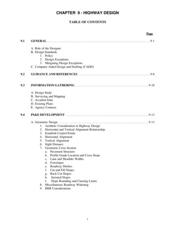
9.1.B. Design Standards. (continued)This documentation supporting the design exception decision shall become a part of the PS&E packagepresented to the owner agency.Documentation of design exceptions should include an explanation of the conditions prohibiting fullstandards and a description of the mitigating measures proposed to maximize operation and safety of thefacility.3. Mitigating Design Exceptions. Tort liability is a major concern of the Government. The designermust ensure that the design process is in compliance with all applicable standards.The exception to standards outlined in FLHM 3-C-2 permits the designer to vary the controlling criteriawhen alternatives merit precedence over standards.The project plans should include curve signs, turn signs, and advisory speed plates for mitigation purposeswhen posted limits cannot be reduced. The MUTCD specifies installation of advisory speed platesfollowing a determination of the safe speed by accepted traffic engineering procedures.An accepted field method of determining safe speed for horizontal curvature uses a slope meter, morecommonly referred to as the ball bank indicator. When advisory speed plates are warranted, the projectengineer should be provided with a listing of curve signs, turn signs, and advisory speed plates needed forthe project as determined by theoretical design speed criteria. Signing normally appears on the plans butoccasionally supplemental studies dictate the need to forward additional data to the field.The project engineer verifies the safe speed of the curves in question using the ball bank indicator or otheraccepted traffic engineering procedures. The engineer can contact a local State, county, or municipaltraffic engineer to arrange for a speed determination if a ball bank indicator is not available on a projectvehicle. See pages 143-145 and Figure III-4 in the Green Book for a discussion on the relationship of ballbank readings and safe speeds. Also see Figure 9-4, Safe Speeds.Table 9-2 establishes signing requirements for curves and turns.Some agencies have criteria other than what is shown in Table 9-2. The designer should check theagencies' standards for conflicts between the two and use the more conservative signing criteria.Determining the appropriate standards to be used for roadway lane and shoulder widths is sometimesdifficult. In some cases, the project may be the only improvement on a route for many years. In othercases, the maintaining authority may have a policy that only resurfacing projects will be applicable to aroute to use available funding for higher priority transportation facilities. In these instances, thecompatibility with adjacent sections of the highway may be the governing criteria. When compatibilitywith adjoining roads is the controlling factor, a design exception is appropriate.Extraordinary cost or adverse environmental impacts could also result in design exceptions. When thehighway operating agency's approved transportation plan specifies less than the standard widths for a route,this width requires documentation as a design exception.The remaining controlling criteria are usually limited to site specific locations. The designer must mitigatethese design exceptions through the normal design process.9-5
9.1.B. Design Standards. (continued)Some RRR projects cannot be surveyed cost effectively in enough detail to identify many of the exceptionsto the controlling criteria, such as super-elevation, grades, etc. These projects place considerable emphasison the engineering judgment of the designer. Any on-site study or field review for RRR projects shoulddocument any identifiable exceptions to standards.Table 9-2Minimum Signing1 for Curves and TurnsSafe Speed 2(km/h)PostedSpeed30or TATT3050TT2540T20orless30Notes:1100A Advisory Speed Plate2C Curve Warning Sign, Reverse Curve Sign(or Winding Road Sign)T Turn Sign, Reverse Turn Sign(or Winding Road Sign)See MUTCD (Section 2C-4 and 2C-5).Determine the safe speed by use of the ball bank indictor.9-6
9.1.C. Computer Aided Design and Drafting.C. Computer Aided Design and Drafting (CADD). Information on Computer Aided Design andDrafting is included in the Federal Lands Highway CADD Manual.9-7
9.2 GUIDANCE AND REFERENCESThe publications listed in this section provided much of the fundamental source information used in thedevelopment of this chapter. While this list is not all inclusive, the publications listed will provide thedesigner with additional information to supplement this manual.A Policy on Geometric Design of Highways and Streets. AASHTO. 1994.Highway Capacity Manual. TRB Special Report No. 209. Transportation Research Board. 1985.Manual on Uniform Traffic Control Devices (MUTCD). DOT, FHWA. 1988.Traffic Control Devices Handbook. DOT, FHWA. 1983.Park Road Standards. U.S. Department of the Interior, National Park Service. 1984.Standard Specifications for Construction of Roads and Bridges on Federal Highway Projects (FP-96).DOT, FHWA. 1995.Standard Specifications for Structural Supports for Highway Signs, Luminaries and Traffic Signals.AASHTO. 1986.Guide for Development of Bicycle Facilities. AASHTO. 1991.A Policy on Design of Urban Highways and Arterial Streets. AASHTO. 1973. (Out of Print).Railroad-Highway Grade Crossing Handbook. Report No. FHWA-TS-86-215, 1986.Intersection Channelization Design Guide. NCHRP 279.An Informational Guide for Roadway Lighting. AASHTO. 1984.A Guide of Accommodating Utilities Within Highway Right-of-Way. AASHTO. 1994.A Guide for Erecting Mailboxes on Highways. AASHTO. 1994.Roadway Lighting Handbook. DOT, FHWA. 1978 (and addendum 1983).Americans with Disabilities Act (ADA) Accessibility Guidelines. Architectural and Transportation BarriersCompliance Board. 1994Roadside Design Guide. AASHTO. 1989A Guide to Standardized Highway Barrier Hardware. AASHTO-AGC-ARTBA. 1995Recommended Procedures for the Safety Performance Evaluation of Highway Features. NCHRP Report350. TRB. 1993Design Risk Analysis (Volume I and II). FHWA-FLP-91-001. FHWA. 19919-8
9.2 Guidance and References. (continued)Standard Practice for Use of the International System of Units (SI). The Modernized Metric System.E380-93. ASTM. 1993Trail Design Manual "Trails for the Twenty-First Century": Planning, Design, and Management Manualfor Multi-use Trails. Rails to Trails Conservancy, 1993Designing Safer Roads. TRB Special Report No. 214. Transportation Research Board. 1987.Horizontal Alignment Design Consistency for Rural Two-Lane Highways. FHWA-RD-94-034. FHWA.19959-9
9.3 INFORMATION GATHERINGThe designer is directed to Chapter 4, Conceptual Studies, for information on scoping, background data,preliminary design standards, and mitigating measures before beginning detailed design activities.A. Design Study. A design study documents considerations and conclusions reached during thedevelopment of a project. Although it may not always result in a formal document, the study provides ahistory of the project from start to completion of the PS&E.When the designer has completed the PS&E, the following applicable data should be available in the files:Project Description:-Description of existing conditions.Comparison of proposed work with "no build" alternative.Extent of selection and examination of alternatives.Identification of deficiencies with costs to correct.Design parameters used.Evaluation of any substantial change in commitments made in the environmental document.Statement regarding hearings advertised, held, or required.Cost estimates including applicable right-of-way acquisition, utility relocation, permits, project costs,construction engineering, incentive/disincentive clauses, and project agreements.Access control requirements.Reasons for deviations from adopted policy and standards.Traffic Data:- Present and design year average daily traffic (ADT) and seasonal average daily traffic (SADT),when applicable, with percentage of (S)ADT used for design hour volume (DHV), for directionalsplit (D), and for trucks (T).- DHV for two-lane, two-way highways, crossroads, and frontage roads.- Turning movements.Special Traffic Data:-Noise impact studies.Signal warrants.Air quality studies.Illumination warrants.Left turning movements.Traffic control plans.Other studies as required.Accident history.Geotechnical and Materials Engineers' reports.Involvements on railroad right-of-way such as crossings, encroachments, etc.Utility involvements.9 - 10
9.3.A. Design Study. (continued)Permit requirements or agreements.Roadway sections, including all new or widened bridges.Pavement structure section.Drainage consisting of hydraulic concepts, floodplain studies, culvert selection, etc.Erosion .Roadside development such as landscaping, aesthetic treatments, etc.Traffic control in terms of delineation, traffic barriers, pavement marking, impact attenuators, etc.Traffic control plans through construction.Related data affecting the ultimate construction and operation of the facility such as right-of-wayconsiderations.B. Surveying and Mapping. Chapter 5 covers the surveying and mapping information the designer canexpect to receive. Ideally the design, survey, geotechnical and conceptual study engineers and the owneragency review the proposed work on the ground and determine the information and limits of the surveyrequired to complete the project.When field reviews are not possible, it is still beneficial for the designer and survey and mapping/locationengineer to discuss the field information required. In many cases the designer's experience with newconstruction, reconstruction, and RRR projects can increase the effectiveness of the survey crew.At some point in the project development process the designer usually provides the appropriate surveyunit with the information to stake the project in the field. This could include notes to establish centerline,set slope stakes, clearing limits, reference points, right-of-way, and other control points necessary tocomplete the work. The designer shall keep the design files purged so the information provided for thestakeouts is current, correct, and reflects the design criteria established for the project. All notes preparedfor field use will require checking to prevent the possibility of providing incorrect data.9 - 11
9.3.C. Accident Data.C. Accident Data. On all projects the accident history should be analyzed and potentially hazardousfeatures and locations identified to determine appropriate safety enhancement. A study of accidents bylocation, type, severity, contributing circumstances, environmental conditions, and time periods maysuggest possible safety deficiencies. The designer should refer to Chapter 8 for details on
The design criteria shown in Table 9-1 represent both desirable and minimum standards. Each design should be evaluated on the basis of desirable design criteria for the safest overall design. Cost, social and environmental factors often require standards that are less th