Transcription
KINETICS Seismic & Wind Design Manual Section D6.0SECTION D6.0 - TABLE OF CONTENTSTitleSectionRevision RecordD6.0AD6.0 -Curb Mounted EquipmentTitleSectionBasic Curb InformationSeismic Forces & Curb Mounted EquipmentD6.1Sheet Metal CurbsBasic Primer for Sheet Metal CurbsD6.2.1Attachment of Equipment to Sheet Metal CurbsD6.2.2Transferring Seismic Forces Through Sheet Metal CurbsD6.2.3Attachment of the Sheet Metal Curb to the Building StructureD6.2.4Limits of Sheet Metal Curbs in Seismic ApplicationsD6.2.5Rules for Using Sheet Metal in Seismic ApplicationsD6.2.6Structural CurbsBasic Primer for Structural CurbsD6.3.1Attachment of Equipment to Structural CurbsD6.3.2Transferring Seismic Forces Through the Structural CurbD6.3.3Attachment of the Structural Curb to the Building StructureD6.3.4Limitations of Structural Curbs in Seismic ApplicationsD6.3.5Rules for Using Structural Curbs in Seismic ApplicationsD6.3.6SECTION D6.0 – TABLE OF CONTENTSPAGE 1 of 1Toll Free (USA Only):International:FAXWorld Wide Web:E-mail:Dublin, Ohio, USA Cambridge, Ontario, CanadaSECTION – icsnoise.comsales@kineticsnoise.comRELEASED ON: 04/11/2014
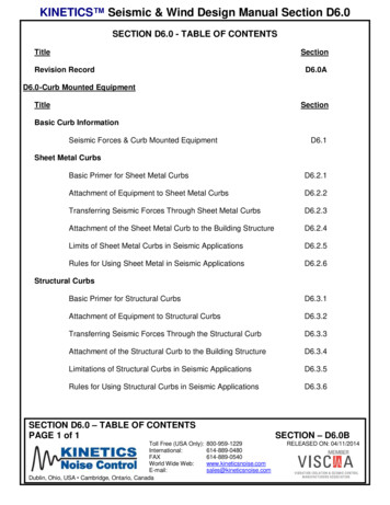
KINETICS Seismic & Wind Design Manual Section D6.1SEISMIC/WIND FORCES AND CURB MOUNTED EQUIPMENTIntroductionSince the introduction of the 97 UBC, all of the building codes have mandated design seismicforces that are much larger in magnitude than were previously specified. One of the features ofthese new codes is that they have written the design horizontal seismic force equation toaccount for the amplification of the accelerations due to increasing flexibility as you go up in abuilding. Therefore, equipment that is mounted on the roof of a building will have design seismicforces that are three times larger than a similar piece of equipment that is mounted on grade.Wind forces also increase with height. These additional forces must be addressed in the design,selection, and installation of supports and restraints for roof top curb mounted equipment.Basic Curb TypesThe roof curbs may be broken down into isolated and non-isolated types. The isolated roofcurbs may be further broken down into sheet metal and structural types. The discussion willstart with the isolated curb types.Sheet Metal Seismic Isolation Curbs:Kinetics Noise Control provides three products that combine isolation with a compatible sheetmetal roof curb. First is the Kinetics Noise Control model KSR Isolation Rail. These railsystems have been designed to address the bulk of the needs of smaller pieces of equipmentup to 20 ft long and up to 5000 lb in weight (Note: under severe seismic or wind load conditions,these limits may be reduced further). The KSR-1 and KSR-2 are seismically restrained steelcoil spring isolation systems that are built to be installed on compatible third party sheet metalroof curbs. Figure D6.1-1 shows a typical cross-section through the springs of a KSRinstallation. Figure D6.1-2 is a typical cross-section through the seismic/wind restraints of theKSR. KSR-1 systems are designed to operate with a system Static Deflection ofwhenloaded, which gives a system Natural Frequency of 3.13 Hz. The KSR-2 systems are intendedto operate with a loaded system Static Deflection of , which produces a system NaturalFrequency of 2.21 Hz. The Static Deflection of the KSR systems is adjustable by adding orremoving the spring coils, which are easily accessible and must be compressed for insertion orwithdrawal.The seismic/wind restraints consist of stainless steel leaves for the horizontal restraints, andreinforced neoprene straps for the vertical restraints. Each KSR installation requires a minimumof one horizontal restraint per curb side. The vertical restraints are required if there is a chancethat the applied loads could generate an uplift condition at any of the equipment corners. Theleaves and straps, when required are attached to the extruded aluminum top rail and the curbside wall through the nailer and sheet metal member as shown in Figure D6.1-2. The locationsfor the restraints are specified by the by Kinetics Noise Control. The required number ofrestraints, horizontal and vertical, is determined by analysis using the Kinetics Noise ControlSeismic/Wind Certification Program.SEISMIC/WIND FORCES AND CURB MOUNTED EQUIPMENTPAGE 1 of 9SECTION – D6.1Toll Free (USA Only):International:FAXWorld Wide Web:E-mail:Dublin, Ohio, USA Cambridge, Ontario, ticsnoise.comsales@kineticsnoise.comRELEASED ON: 04/11/2014
KINETICS Seismic & Wind Design Manual Section D6.1Figure D6.1-1; Typical Cross-Section through KSR Showing Isolation Springs2.051.52KSR-17.42 Free Ht.6.42 Oper. Ht.SupportedRoof TopEquipmentClosed-Cell Foam TapeWeather Seal by KineticsExtruded AluminumTop Rail By Kinetics7.40KSR-28.67 Free Ht.6.72 Oper. Ht.Neoprene Weather Sealby Kinetics.Pre-Punched AluminumCover Strip by Kinetics.Steel Coil SpringIsolation by KineticsExtruded AluminumBottom Rail by Kinetics.1.83 Bottom RailCaulking by Kinetics.Sheet Metal Roof Curb by Others.Compatible sheet metal roof curbs will allow the attachment of the restraint elements to theirinner perimeter with hardware that penetrates the sheet steel body of the curb itself. KSRisolation rails are not generally compatible with sheet metal roof curbs whose nailer is mountedon top of the sheet metal curb body unless some form of steel element is fitted that positivelyattaches to the curb wall and fully surrounds the hardware that attaches the lower end of therestraint and generates a continuous steel load path between the restraint and the roofstructure.The second product offered by Kinetics Noise Control is the KSCR with 1” and 2” deflectionversions identified as the KSCR-1 and KSCR-2 isolation rail factory mounted on a factoryprovided sheet metal curb assembly A typical cross-section through the KSCR is shown inFigure D6.1-3.SEISMIC/WIND FORCES AND CURB MOUNTED EQUIPMENTPAGE 2 of 9SECTION – D6.1Toll Free (USA Only):International:FAXWorld Wide Web:E-mail:Dublin, Ohio, USA Cambridge, Ontario, ticsnoise.comsales@kineticsnoise.comRELEASED ON: 04/11/2014
KINETICS Seismic & Wind Design Manual Section D6.1Figure D6.1-2; Typical Cross-Section through KSR Showing RestraintsPre-Punched Holes in Extruded AluminumTop Rail for Mounting Hardware by Kinetics.Seismic/Wind Restraints Quantity andLocation Pre-Determined by KIneticsCurb Attachment Hardware forSeismic/Wind Restraints by Kinetics.Figure D6.1-3; Typical Cross-Section through a KSCRSupported Roof TopEquipment.Extruded Aluminum Top Rail.Steel Coil SpringIsolation.KSCR-121.42 Free Ht.20.42 Oper. Ht.Seismic/Wind Restraint.Neoprene Weather Seal.Poly Spring Cup &Neoprene Washer.Pre-Punched AluminumCover Strip.KSCR-222.67 Free Ht.20.72 Oper. Ht.Flashing by nt Stripby Others.16 Gage Galvanized Steel Reinforcedwith Treated 2x4's 30" O.C.SEISMIC/WIND FORCES AND CURB MOUNTED EQUIPMENTPAGE 3 of 9SECTION – D6.1Toll Free (USA Only):International:FAXWorld Wide Web:E-mail:Dublin, Ohio, USA Cambridge, Ontario, ticsnoise.comsales@kineticsnoise.comRELEASED ON: 04/11/2014
KINETICS Seismic & Wind Design Manual Section D6.1As with the KSR-1 & -2, The KSCR-1 is aStatic Deflection isolation system, and theKSCR-2 is aStatic Deflection isolation system. The horizontal and vertical restraints usedfor the KSCR are the same ones used on the KSR. At least one horizontal restraint per curbside wall is required, and more are added as indicated by analysis through the Kinetics NoiseControl Seismic/Wind Certification Program. The vertical restraints are added where indicatedby the analysis. Typically the curb itself is 16 Gage Galvanized steel reinforced with structuralgrade 2x4’s at 30 On Center. Curb heights greater may require the use of heavier gage sheetsteel in order to carry the seismic and wind loads without danger of buckling failure.The third isolation rail product offered by Kinetics Noise Control is the HD-KSR. This product isa structural steel element that is intended for installation on compatible third party sheet metalcurbs. It’s more rugged construction than the KSR products make it more suitable for higherseismic or wind loads on smaller units and still allows good performance for units up into the12,000 lb, 40 ft long class. The HD-KSR is also available in 1” and 2” static deflectionversions. Figure D6.1-4 shows a plan view, elevation and a section through the critical cornerelement of the HD-KSR.Figure D6.1-4; HD-KSR Plan View, Elevation and Section of corner restraint elementsSEISMIC/WIND FORCES AND CURB MOUNTED EQUIPMENTPAGE 4 of 9SECTION – D6.1Toll Free (USA Only):International:FAXWorld Wide Web:E-mail:Dublin, Ohio, USA Cambridge, Ontario, ticsnoise.comsales@kineticsnoise.comRELEASED ON: 04/11/2014
KINETICS Seismic & Wind Design Manual Section D6.1A significant difference between the HD-KSR and the lighter duty KSR and KSCR is that theprimary restraint elements are located at the corners of the curb. This is done because a) thesheet metal corner is much more able to resist lateral forces than are the central portions of thecurb side walls and b) because it is in the corners where the peak seismic and wind overturningloads are generated.Structural Seismic Isolation CurbsKinetics Noise Control provides the model ESR-1, ESR-2, and ESR-4 structural seismicisolation curb systems. They are, respectively,, 2 , andStatic Deflection isolationsystems. The intended system Natural Frequencies are 3.13 Hz, 2.12 Hz, and 1.56 Hzrespectively.Figure D6.1-5; Typical ESR Pedestal Installation3-Axis NeopreneSeismic Snubber.Welded SteelSpring/Restraint Pedestal.Leveling Bolt.C4x5.4 Standard Top Rail.C6x8.2 Top Rail for Drain Pans.Steel Coil Spring& Neoprene Isolation.Continuous GalvanizedSteel Curb Perimeter. ESR-1 / -220.25WoodNailers.ESR-421.25RemovableAccess Panel.Building Structural Steel(ESR-1 / -2) - 12.50(ESR-4) - 14.50SEISMIC/WIND FORCES AND CURB MOUNTED EQUIPMENTPAGE 5 of 9SECTION – D6.1Toll Free (USA Only):International:FAXWorld Wide Web:E-mail:Dublin, Ohio, USA Cambridge, Ontario, ticsnoise.comsales@kineticsnoise.comRELEASED ON: 04/11/2014
KINETICS Seismic & Wind Design Manual Section D6.1Figure D6.1-6; Typical Cross-Section through an ESR Pedestal InstallationEquipment Outline.Galvanized Flashing.EPDM Weather Seal.Wood Nailer.C4x5.4 Top Rail.Optional External Insulation.3-axis NeopreneSnubber.Cover Strip.Screws.Welded SteelSpring/RestraintPedestal.Built-up Roof, Membrane& Insulation by Others.Building StructuralSteel.(ESR-1 / -2) - 4.00 Min.(ESR-4) - 6.00 Min.The seismic forces are transferred from the equipment to the top rail through fasteners or weldsat each pedestal location. The size and number of the fasteners, and the size and length ofweld required at each pedestal is specified by the Kinetics Noise Control Seismic/WindCertification Program. The loads are transferred to the welded steel spring restraint pedestalthrough the 3-axis neoprene snubber assembly. The loads then are transferred from thepedestal to the building structure. The ESR is intended to be attached directly to the buildingstructural steel either by bolting or welding. Mounting holes are provided for three (3) 5/8Bolts/Anchors in the base plate of each pedestal. An equivalent amount of weld is specified byKinetics Noise Control for each pedestal. Attachment of the ESR to the building structural steelwill maximize the seismic capacity of the system. If the ESR is to be attached to concrete orsome type of wooden structure, special analysis and additional components will be required tomake an adequate attachment, and in most instances, the full capacity of the ESR will not berealized.When larger units are encountered, in particular when in conjunction with higher seismic orwind load conditions, it will be necessary to upgrade from the ESR to the MegaCurb. TheMega Curb is a full structural curb that can be tailored to units weighing as much as 50,000 lb.Its structure is of I-Beams and other structural shapes and its base forms a rigid box onto whichthe isolation/restraint system can be integrated. It is available with, 2 , andStaticDeflection isolation systems. These are highly custom units because of the nature of theSEISMIC/WIND FORCES AND CURB MOUNTED EQUIPMENTPAGE 6 of 9SECTION – D6.1Toll Free (USA Only):International:FAXWorld Wide Web:E-mail:Dublin, Ohio, USA Cambridge, Ontario, ticsnoise.comsales@kineticsnoise.comRELEASED ON: 04/11/2014
KINETICS Seismic & Wind Design Manual Section D6.1forces that they must resist and are custom designed from the base up for each installation. A“typical” section is illustrated below to offer an idea of how these look, but all of the membersare subject to change to optimize them based on the actual load requirements.Figure D6.1-7; MegaCurb SectionApplication of Isolated Roof CurbsWith each successive version of the IBC and other building codes, the design loads haveincreased. As a result, restraint systems that were quite adequate for a particular piece ofequipment 5–10 years ago, are no longer substantial enough to meet the restraint requirementfor the same piece of equipment today. As a result, the ratings on some of the older modelisolation rails have dropped. The KSR & KSCR for instance, were generally useful forequipment weights of up to 10,000 lb and lengths of up to 40 ft. They are now good for half ofthat (5,000 lb and 20 ft). The HD-KSR was designed to fill in the void that resulted from thedecreased rating potential of the KSR. It is suitable for units in the 5,000 lb to 12,000 lb, 40 ftlong class for most seismic and wind conditions.As the sizes increase beyond 12,000 lb and 40 ft of length, attachment to a sheet metal roofcurb becomes impractical. For these applications, ESR’s and MegaCurb’s are required. Whenattaching to steel and if crossbracing can be fitted, the ESR’s are generally good for equipmentup to 20,000 lb and 50 ft long. If anchored to concrete or if there are limitations on the ability tocrossbrace, the ESR capacity will drop off.For extremely large or heavy units, in particular those subjected to extreme wind or seismicforces, a MegaCurb will likely be required. These are custom tailored to the application andhave been used on units as heavy as 100,000 lb and as long as 80 ft.Non-Isolated Sheet Metal Seismic Roof Curbs:Except for extremely high capacity non-isolated MegaCurbs, Kinetics Noise Control does notproduce a non-isolated roof curb. For smaller curbs however, Kinetics Noise Control canSEISMIC/WIND FORCES AND CURB MOUNTED EQUIPMENTPAGE 7 of 9SECTION – D6.1Toll Free (USA Only):International:FAXWorld Wide Web:E-mail:Dublin, Ohio, USA Cambridge, Ontario, ticsnoise.comsales@kineticsnoise.comRELEASED ON: 04/11/2014
KINETICS Seismic & Wind Design Manual Section D6.1provide custom kits to attach the supported piece of equipment to a roof curb that is built byothers, or to the building structure. The attachment of equipment to third party curbs is an issuethat has not been well addressed by either the equipment manufacturers or the curbmanufacturers and there are no standardized components that will work efficiently for all cases.Except in the case of small mushroom fans, for which a kit is available, KNC must be providedwith dimensionally accurate sections of the unit and of the curb so that appropriate componentscan be manufactured.For smaller mushroom fans or similar pieces of equipment, Kinetics Noise Control offers themodel KSMF, Figure D6.1-8. A minimum of four (4) clips are required for each curb.Additional kits may be required based on an analysis by Kinetics Noise Control. The requirednumber and location of each kit are specified by Kinetics Noise Control.Figure D6.1-8; Typical KSMF Seismic Attachment Kit InstallationEquipmentWoodenNailerKSMFCurb byOthersPreferredInstallationKSMF Kinetics SeismicBracket Kit for CurbMounted EquipmentWhen reviewing the attachment of equipment restraints to sheet metal curbs, the analysisperformed by Kinetics Noise Control also looks at the curb side walls if enough information isprovided in the submittal sent to Kinetics. If the curb side walls do not appear to be able to carrythe design seismic or wind loads, Kinetics Noise Control will make recommendations thatreinforcements are to be used for the curb side walls and/or that heavier gage steel is to beused in the curb side walls in order to meet the design load requirements. If reinforcements areindicated by the analysis, Kinetics Noise Control can provide the model KSVR, Figure D6.1-9,curb side wall reinforcement kit. The KSVR kit is intended to carry the vertical loads generatedby the equipment and leave the curb side walls to carry the horizontal seismic loads. TheSEISMIC/WIND FORCES AND CURB MOUNTED EQUIPMENTPAGE 8 of 9SECTION – D6.1Toll Free (USA Only):International:FAXWorld Wide Web:E-mail:Dublin, Ohio, USA Cambridge, Ontario, ticsnoise.comsales@kineticsnoise.comRELEASED ON: 04/11/2014
KINETICS Seismic & Wind Design Manual Section D6.1analysis performed by Kinetics Noise Control will recommend the number and spacing for thereinforcements.Figure D6.1-9; Typical KSVR Reinforcement Kit InstallationRoof Curb by OthersHCurbHeightHrMeasure&Cut to FitS Max. SpacingKSVR Reinforcement Kit by KineticsSEISMIC/WIND FORCES AND CURB MOUNTED EQUIPMENTPAGE 9 of 9SECTION – D6.1Toll Free (USA Only):International:FAXWorld Wide Web:E-mail:Dublin, Ohio, USA Cambridge, Ontario, ticsnoise.comsales@kineticsnoise.comRELEASED ON: 04/11/2014
KINETICS Seismic & Wind Design Manual Section D6.2.1BASIC PRIMER FOR SHEET METAL CURBSRooftop HVAC units normally require some type of penetration through the roof to allow air tobe transferred to and from the unit. These pieces of equipment are supported on a curb that isbuilt around the penetration in the roof. This allows the roof to be attached to the curb andpermanently sealed from the elements.One of the most popular constructions for curbs is the sheet metal curb. Sheet metal curbs arelight, economical, and easily installed. They may be field fabricated or purchased in prefabricated sections from a curb manufacturer. The plan view of the curb may be rectangular,square, or “L” shaped. In this document, and the ones to follow, we will be concerned with curbsthat have a rectangular plan view. Shown in Figure 6.2.1-1 is a plan view of a rectangular sheetmetal curb.Figure 6.2.1-1; Plan View of Rectangular Sheet Metal CurbSIDE DLaLbSIDE BSIDE ASIDE CThe two long sides will be identified as SIDE A and SIDE C as shown in Figure 6.2.1-1. Theshort sides will be labeled as SIDE B and SIDE D, as in figure 6.2.1-1. The term La will be theinside length of the long sides of the curb. The term Lb will represent the inside length of thecurb’s short sides. Another term we will need to define now for later use is the inside perimeterof the curb, Lp. The value of the inside perimeter will be as follows:Lp2 La(Eq. 6.2.1-1)LbFigure 6.2.1-2 shows two section views through a typical sheet metal curb. Each of the viewsrepresents a slightly different construction. Some manufacturers use a 2 X 2 nailer, others a 2 X4 nailer and some a 1 X () Nailer. The primary purpose of the wooden nailer is to permit the roofflashing to be easily attached to the curb. A secondary purpose is to aid in the attachment of theequipment. Because the upper edge of the curb is relative pliable to forces acting against itBASIC PRIMER FOR SHEET METAL CURBSPAGE 1 of 2Toll Free (USA Only):International:FAXWorld Wide Web:E-mail:Dublin, Ohio, USA Cambridge, Ontario, ticsnoise.comsales@kineticsnoise.comSECTION – D6.2.1RELEASED ON: 04/11/2014
KINETICS Seismic & Wind Design Manual Section D6.2.1from the side, the wooden nailer also adds to the lateral strength to the curb. Unfortunately thewood used is often sub-standard and apart from cursory loads, cannot be counted on to carrymore than the roof flashing. To aid in the attachment of equipment when working withapplications involving wind or seismic resistance, roof curbs should as a minimum, have a goodgrade of 2 x () lumber specified for the nailer.Figure 6.2.1-2; Typical Sheet Metal Curb Sections2X2NAILERHt2X4NAILERtHIn Figure 6.2.1-2, H is the height of the curb. Normally, the standard height of the curb is 14inches. This provides enough standoff to accommodate most roofing systems and still allow forthe flashing. The height of the curb can however, vary depending on the requirements of theequipment, the sound attenuation equipment, and the slope of the roof, if any. The term t is thethickness of the sheet metal used to construct the curb. There are three basic materialthickness values that are commonly used for the construction of curbs: 18 gage(0.0478 inches), 16 gage (0.0598 inches), and 14 gage (0.0747 inches).The curb height, H, and the sheet metal thickness, t, will determine the loads that can becarried by the curb, as we shall see in Documents 6.2.3 and 6.2.4. It should be mentioned here,as well as Document 6.2.3, that all of the loads must be carried in the plane side walls of thecurb. The sides of the curb do not behave as a beam. The curb walls are really very thin platesthat are loaded in compression on their long edges due to the equipment weight, and in uniformshear along each edge. The principal failure mode of the curb wall will be buckling. Documents6.2.3, 6.2.4, 6.2.5, and 6.2.6 go into greater detail concerning the applications and limitations ofsheet metal curbs in areas prone to earthquakes or high winds.BASIC PRIMER FOR SHEET METAL CURBSPAGE 2 of 2Toll Free (USA Only):International:FAXWorld Wide Web:E-mail:Dublin, Ohio, USA Cambridge, Ontario, ticsnoise.comsales@kineticsnoise.comSECTION – D6.2.1RELEASED ON: 04/11/2014
KINETICS Seismic & Wind Design Manual Section D6.2.2ATTACHMENT OF EQUIPMENT TO SHEEP METAL CURBSIntroductionThere are a wide variety of pieces of equipment, equipment manufacturers and curb types tothe point that devising a “standard” set of brackets and hardware to inter-connect the two is notpractical. In the past, many pieces of equipment were not physically fastened to the curb andrelied on gravity and the boxing in “picture frame” relationship between the equipment and curbto hold the equipment in place. In geographical areas that can experience high, or evenmoderate, wind and/or seismic loads, gravity and the “boxing” affect have proven to beinadequate and a more positive method is required. This document will present severaldifferent styles of attachment brackets and attachment configurations.The transfer of loads is also made more complicated by the fact that curb side walls can carryloads only in the plane of the side wall. They cannot carry significant loads that actperpendicular to the side wall. They do however, carry the weight load of the equipment as adistributed compressive load in the side wall and when combined with significant horizontalseismic or wind loads, the combination can become a problem. Depending on the equipmentprofile or weight and the seismic or wind conditions, uplift forces can occur and must beaddressed. For a complete discussion of the transfer of forces through a sheet metal curb referto document D6.2.3.Small Hard Mounted Equipment Attachments/RestraintsThere are many different types of equipment that are mounted on sheet metal roof curbs. Wewill start with the smaller types. Typical of these are the powered ventilator “mushroom” fans,louvers, and un-powered ventilators. A typical “mushroom” fan attached to a curb is shown inFigure 6.2.2-1. The ventilators and louvers usually have weights that are low enough andperimeters small enough that they are sufficiently rigid to carry the required uplift forces withoutdamage. Therefore, they are an exception to the rules in the previous paragraph. Also, thecurbs for ventilators and louvers often have the wooden nailer attached directly to the top of thesheet metal. Thus, the attachment of the equipment to the curbs has usually involved fasteningdirectly to the wood of the nailer.ATTACHMENT OF EQUIPMENT TO SHEEP METAL CURBSPAGE 1 of 9SECTION – D6.2.2Toll Free (USA Only):International:FAXWorld Wide Web:E-mail:Dublin, Ohio, USA Cambridge, Ontario, ticsnoise.comsales@kineticsnoise.comRELEASED ON: 04/11/2014
KINETICS Seismic & Wind Design Manual Section D6.2.2Figure D6.2.2-1; Typical “Mushroom” Fan on Curb1324BB/20.75 TYP 2.25TYPA/2AATTACHMENT OF EQUIPMENT TO SHEEP METAL CURBSPAGE 2 of 9SECTION – D6.2.2Toll Free (USA Only):International:FAXWorld Wide Web:E-mail:Dublin, Ohio, USA Cambridge, Ontario, ticsnoise.comsales@kineticsnoise.comRELEASED ON: 04/11/2014
KINETICS Seismic & Wind Design Manual Section D6.2.2Figure D6.2.2-2; Typical Restraint Installation for “Mushroom” FansKSMF-1 KINETICS SEISMICBRACKET KIT FOR CURBMOUNTED ILERFigure D6.2.2-2 shows a typical installation of a seismic equipment bracket kit provided byKinetics Noise Control. For curb-mounted ventilators and louvers the model name for the kit isthe KSMF-1 (Kinetics Seismic Mushroom Fan), see Chapter P1 for product details and ratings.This bracket design allows the attachments to be made to the sheet metal part of the curb. Thethreads on the sheet metal screws must completely engage the sheet metal of the curb in orderto develop full strength. Sheet metal screws of the appropriate diameter and length toaccommodate most curb designs are provided in the kit by Kinetics Noise Control.ATTACHMENT OF EQUIPMENT TO SHEEP METAL CURBSPAGE 3 of 9SECTION – D6.2.2Toll Free (USA Only):International:FAXWorld Wide Web:E-mail:Dublin, Ohio, USA Cambridge, Ontario, ticsnoise.comsales@kineticsnoise.comRELEASED ON: 04/11/2014
KINETICS Seismic & Wind Design Manual Section D6.2.2Shown also in Figure D6.2.2-1 is the locating scheme for this type of seismic bracket kit. Thedimensions “A” and “B” are the locations of the restraints as specified on the Kinetics Seismicand/or Wind Certification sheet.A minimum of four kits are required for each piece of equipment. The restraints are placed tokeep the horizontal wind, and/or seismic force loads in the plane of the curb walls. More may berequired per the certification sheet. They should be evenly spaced along the sides.Large Hard Mounted Equipment Attachments/RestraintsLarger pieces of rooftop equipment such as air handling units, makeup air units, etc. areconsiderably more problematic. Because of their size, the rocking forces that they generate canexceed the capacity of many lighter duty curb walls to resist them. The combinations of weight,compressive and uplift forces in combination with the wind or seismically generated horizontalforces can require an increased gage thickness or some form of positive reinforcement. Whenattaching larger equipment to these types of curbs, it is essential to obtain a statement from thecurb supplier that it will indeed be adequate for the job.Having said that, the focus of this section is connecting the equipment to the curb and for ourpurposes, we will assume that the curb is substantial enough.The first key requirement in generating the attachment is that there must be a well-defined loadpath that leads completely from the equipment to the structure on which the curb is placed.Each component in the load path must be capable of resisting the total combined loads that itmight be subjected to. For this reason, it becomes critical to eliminate the inconsistent andrelatively unpredictable wooden nailer member from the load path. Connections can be madethrough the nailer (so that it might function as a spacer), however restraint against significantseismic or wind loads should not be dependent on its structural integrity.The second key major issue that is encountered when restraining equipment to curbs is thatany interconnecting bracket or connection device must be fully capable of resisting the fullrange of loads that it might encounter. Devising bracketry that can bridge between equipmentand a curb and resist horizontal loads is relatively simple. Sheet metal “L” shaped bracketsalong the lines of the KSCM-1 (shown in the figure below) will do a good job in resisting theseforces.Care should be taken when installing this type of restraint that a) there are no uplifting loadspresent that could cause the unit to lift and b) that the restraints are located in areas where thecurb wall is resistant to forces that act at 90 degrees to the its axis. If the curb wall is notsubstantial enough or backed up by a cross brace or end panel, loads applied in a sidewaysdirection will simply cause it to buckle inward or outward.Figure D6.2.2-3; KSCM-1 Horizontal Load Resistant Sheet Metal RestraintATTACHMENT OF EQUIPMENT TO SHEEP METAL CURBSPAGE 4 of 9SECTION – D6.2.2Toll Free (USA Only):International:FAXWorld Wide Web:E-mail:Dublin, Ohio, USA Cambridge, Ontario, ticsnoise.comsales@kineticsnoise.comRELEASED ON: 04/11/2014
KINETICS Seismic & Wind Design Manual Section D6.2.2WEATHER SEALBY OTHERS.EQUIPMENT3 PLC.S PERBRKT1/8KSCM-1 KINETICS SEISMICRESTRAINT BRACKET KIT.ATTACH TO CURB PRIOR TOSETTING EQUIPME
KINETICS Seismic & Wind Design Manual Section D6.1 SEISMIC/WIND FORCES AND CURB MOUNTED EQUIPMENT PAGE 2 of 9 SECTION – D6.1 Toll Free (USA Only): 800-959-1229 RELEASED ON: 04/11/2014 International: 614-889-0480 FAX 614-889-0540 World Wide Web: www.kineticsnoise.