Transcription
Laser-based displays: a reviewKishore V. Chellappan, Erdem Erden, and Hakan Urey*Optical Microsystems Laboratory, Department of Electrical Engineering, Koç University, Istanbul, Turkey*Corresponding author: hurey@ku.edu.trReceived 11 January 2010; revised 9 June 2010; accepted 9 July 2010;posted 13 July 2010 (Doc. ID 121708); published 4 August 2010After the invention of lasers, in the past 50 years progress made in laser-based display technology hasbeen very promising, with commercial products awaiting release to the mass market. Compact laser systems, such as edge-emitting diodes, vertical-cavity surface-emitting lasers, and optically pumped semiconductor lasers, are suitable candidates for laser-based displays. Laser speckle is an important concern,as it degrades image quality. Typically, one or multiple speckle reduction techniques are employed inlaser displays to reduce speckle contrast. Likewise, laser safety issues need to be carefully evaluatedin designing laser displays under different usage scenarios. Laser beam shaping using refractive anddiffractive components is an integral part of laser displays, and the requirements depend on the sourcespecifications, modulation technique, and the scanning method being employed in the display. A varietyof laser-based displays have been reported, and many products such as pico projectors and laser televisions are commercially available already. 2010 Optical Society of AmericaOCIS codes: 030.6140, 080.2175, 120.2040, 140.2010, 140.3298, 140.3300.1. IntroductionLaser-based displays have been under active development over the past 50 years, but commercial viability of the technology was limited mainly due to thelarge size and high cost of laser sources. Recent developments in visible laser technology are expectedto give momentum to the development of laser-baseddisplays for the consumer market. Earlier laserprojectors were inspired by the beam-scanning technology used in cathode ray tubes. The quest forminiaturization and high efficiency replaced themodulators and scanning technologies in these typeof projectors with directly modulatable laser sourcesand scanning mirrors based on micro-electromechanical systems (MEMS) technology, respectively. Although diode laser technology could producepowerful blue and red lasers based on gallium nitride(GaN) and aluminum indium gallium phosphide(AlInGaP), respectively, a direct emitting green laserdiode was not available until recently. Nichia Corporation and Osram Opto Semiconductors demonstrated 515 nm direct emitting laser diodes based0003-6935/10/250F79-20 15.00/0 2010 Optical Society of Americaon indium gallium nitride (InGaN), which isexpected to replace less-efficient frequency doubledgreen lasers. One of the laser-based displaysavailable on the market is “LaserVue,” a laser rearprojection television from Mitsubishi. Other companies, such as Microvision, Alcatel-Lucent, Light BlueOptics (LBO), and Explay, are also developing theirown laser display architectures for the mass market.Requirements on the source largely depend on thedisplay architecture. For compact laser projectorsfor mobile devices, wall plug efficiency of the lasersource is an important consideration. Although alaser-based display can offer a wide color gamut compared with other display technologies, it also comeswith a problem specific to laser light, the speckle,which results from the coherence of laser light.This review is on display technologies with lasersas light sources but excludes laser shows, which display only a low amount of information. Section 2deals with different laser technologies available andconsiders the advantages and disadvantages of eachtechnology as well as discusses potential technologies. Sections on display white balancing (Section3) and laser safety (Section 4) are included beforethe discussion on speckle in Section 5. In Section6, different beam-shaping techniques are discussed,1 September 2010 / Vol. 49, No. 25 / APPLIED OPTICSF79
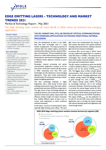
and, finally, in Section 7, laser-based display systemsare reviewed.2. Lasers and Requirements for DisplaysEven though the idea of using lasers for displays wasproposed in the 1960s [1], it is the availability of lasers emitting red, green, and blue colors that triggered the recent development of portable laserprojectors. An immediate advantage of using spectrally pure laser light for displays is the wide colorgamut it can produce. Although gas lasers are available with a wide range of wavelengths, being bulkyand less efficient makes them unsuitable for themass production display market. Moreover, they require external modulators, which increase the costand complexity of the system. An example systemis the laser projector reported by Kim et al., whichused a Kr–Ar laser system with beam scanning[2]. Requirements of the laser source depend onthe architecture of the display. For a flat panel backlit display, the laser beam M 2 parameter can be a fewhundred times larger than that of a diffraction limited beam [3]. Display systems based on the flyingspot approach are considered to be more suitablefor mobile devices [4]. Such an approach requiresthat the laser beam be collimated while maintainingthe small beam size, which places restrictions on theselection of the source. As a TEM00 laser beam can beconsidered as a true point source, such a beam is theideal choice of the designer in this case. It is claimedthat a fast moving spot can be perceived about 30%smaller compared to a static spot, thereby increasingthe line resolution [5]. In the following sections, thestate of the art in laser systems, such as edge-emitting laser diodes, diode-pumped solid-state lasers,vertical-cavity surface-emitting lasers (VCSELs),and optically pumped semiconductor lasers (OPSLs),is reviewed.A.Edge-Emitting Laser DiodesIn 1962, the first semiconductor laser based on GaAswas invented independently by Hall et al., Nathan etal., and Quist et al. [6–8]. These devices requiredcryogenic temperatures, and they were operated inthe pulsed mode. Continuous wave (CW) operationat room temperature was later demonstrated byAlferov et al. and Hayashi et al. with a heterojunctionapproach, which gave rise to an efficient confinementof carriers and photons to the active region of the device [9,10]. Later, the introduction of fiber optic communication systems proved that the invention of thesemiconductor laser was one of the revolutionarysteps in the history of lasers.Semiconductor diodes emitting in the visible region are made of GaInN/GaN and AlGaInP/GaAs[11]. Direct emission green lasers were not available,but recently Nichia Corporation reported devicesbased on InGaN, which emits at 515 nm. Osram, Incorporated, also reported their InGaN-based 50 mWgreen laser which operates at 515 nm. LaserVue, therecent laser television product from Mitsubishi, usesF80APPLIED OPTICS / Vol. 49, No. 25 / 1 September 2010red and blue edge-emitting diodes based on modifiedAlGaInP and GaN material systems [12]. The structure of an edge-emitting diode laser is shown schematically in Fig. 1.Despite having the advantage of being directlymodulatable, the output wavelength of this type oflasers can vary with the junction temperature, whichwill in turn adversely affect the color balance of thedisplay, if left uncontrolled. For a red laser diode, thedeviations from the specified wavelength should beless than 0:5 nm, whereas power variations shouldbe kept below 0.7%. Temperature stabilization canbe done with the help of thermoelectric cooling devices [13]. Other disadvantages of lasers with thisarchitecture are the limited output power and thehighly astigmatic beam. In order to obtain highpower, an array of diodes is often used. Althoughhigher power can be obtained from such an array,the fill factor is much less compared to single emitters, and special techniques are required for producing uniform illumination and for fiber coupling [14].Also, because of the mismatch in the coefficient ofthermal expansion of different layers of a diode laserarray and that between the laser bar and its heatsink, the individual emitters may not appear on aline while in operation. This artifact is called the“smile” and produces a nonlinear array of emitters,which makes beam shaping and fiber coupling a difficult task [15]. In order to correct wavefront errorscaused by defocus, aberrations, and misalignment ofthe source and lens, corrector phase plates can beused [16]. More about beam shaping is discussedin Section 6. Despite having these drawbacks, usingan array of emitters has the advantage of reducedpffiffiffiffiffispeckle contrast in the display by a factor of 1 M,where M is the number of uncorrelated speckle patterns generated by the emitters [17]. The speckle issue is discussed in Section 5. The article by Endrizet al. describes different high-power laser arraysand the operating parameters in detail [18].Fig. 1. (Color online) Structure of an edge-emitting diode laserand its output intensity distribution (taken from Ref. [168]).
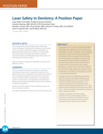
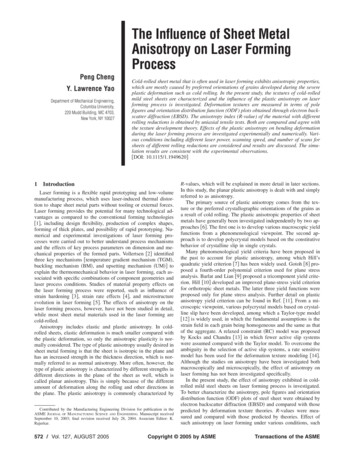
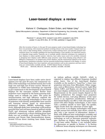
B.Diode-Pumped Solid-State LasersDiode-pumped lasers are capable of generating wattsof optical power at the primary wavelengths ofinterest through nonlinear frequency conversion processes. The red-green-blue (RGB) laser system reported by Hollemann et al. used such an approachto produce an RGB combined optical power of 18 W[19]. Another system by Nebel and Wallenstein demonstrated the generation of laser light with outputpowers of up to 7:1 W at 629 nm, 6:9 W at 532 nm, and5:0 W at 446 nm. The white output power was 19 W,produced with 110 W of optical pumping with diodelasers [20]. But these kinds of systems are costly andrequire complicated optical setups for the frequencyconversion processes. As there was no direct emittinggreen semiconductor lasers, most of the display products use the frequency doubling of infrared light forproducing green. The Corning Green Laser G-1000module uses a distributed Bragg reflector laser operating at 1060 nm [21] followed by frequency doublingin a periodically poled lithium niobate waveguide[22]. Figure 2 illustrates the operation of this laserunit. The entire unit can be enclosed in a volumeof 0:69 cc. The small form factor and high opticalpower output make this laser suitable for smallprojectors.The green light source in Mitsubishi’s laser television is a 15 emitter array of lasers emitting frequencydoubled 532 nm light. In the air-cooled version, thismodule, with a volume of 5 cc, could generate 3:8 Wof green light [12]. There are many reports in the literature that demonstrate generation of the primarycolors based on nonlinear optical frequency conversion processes [23,24]. Recently an RGB laser sourcewas demonstrated based on frequency conversion ina single lithium tantalate crystal [14]. The Evans &Sutherland Laser Projector (ESLP) uses laser systems that employ a nonlinear frequency conversionprocesses to produce the primaries at 631, 532,and 448 nm [25].C.edge-emitters, they can be fabricated as monolithicarrays, eliminating the need for single high-poweredlasers and allowing for parallelism in drawing theimage [27].Firecomms, Limited, produce low-power ( 1 mW)red VCSELs with an AlGaInP active region, whichemit in the 650–690 nm region [28]. But the use ofthis wavelength region is not preferred for displays,as the human eye is less responsive here, requiringhigher optical power from the red for effective whitebalancing of the display. More about color balancingis discussed in Section 3.Necsel demonstrated high-power RGB laser arraysof extended cavity surface-emitting lasers. This special laser structure called the Novalux ExtendedCavity Surface-Emitting Laser (NECSEL) uses intracavity frequency doubling of infrared light fromVCSELs with an InGaAs active region to producevisible light at 615, 532, and 465 nm [29]. Each singleemitter of the array could generate a power of morethan 100 mW. One of the advantages is that,although the efficiency can vary, the output wavelength of this laser system is not temperature sensitive, as a volume Bragg grating is used as the outputcoupler. Figure 4 shows the RGB units of these lasers. The green and blue units generate 3 W, whilethe red unit emits more than 4 W.D.Optically Pumped Semiconductor LasersThis class of lasers is said to deliver high opticalpower with good beam quality. In contrast toVCSELs, where electrical current is used for triggering and maintaining lasing, here optical pumping isused to trigger and maintain it. A small drawback isthat the external cavity of this type of laser requiresalignment. But the high power and good beam quality make them attractive for display applications.Vertical-Cavity Surface-Emitting LasersDisplay applications sometimes require high outputoptical power and good beam quality, but conventional semiconductors are unable to meet both needsat the same time. VCSELs use a surface-emittingstructure, in contrast to the edge-emitting conventional diodes, giving better beam quality. The firstof this type of diodes was introduced by Soda et al.in 1979 [26]. The beam is circular, but here also,the output power is limited and stacking of diodesis necessary to produce high optical powers. Figure3 shows the typical architecture of surface-emittinglaser diodes. An advantage of VCSELs is that, unlikeFig. 2. Operation of the G-1000 laser from Corning. Taken fromRef. [22], Copyright 2008 Society for Information Display.Fig. 3. (Color online) Structure of a VCSEL and its outputintensity distribution. Taken from Ref. [168].1 September 2010 / Vol. 49, No. 25 / APPLIED OPTICSF81
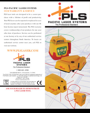
10%–20% with power outputs of 50–100 mW forgreen and 150–300 mW for red. A review of this classof lasers, which are also called semiconductor disklasers, may be found in Refs. [35,36].3. White Balancing and Throughput EvaluationFig. 4. (Color online) NECSEL arrays in operation. Photocourtesy of Necsel Intellectual Property, IncorporatedFigure 5 shows the structure of an OPSL employingthe side-pumping scheme.The importance of this technology is the possibilityof producing high power with good beam quality andthe proposed scalability [30]. More than 8 W of optical power was produced at 1000 nm with an M2 valueof 1:8 by Lutgen et al. [31]. Kim et al. demonstrated2:7 W green and 1:4 W blue lasers with good beamquality using an end-pumping scheme in order to improve pumping efficiency [32]. The Genesis series ofhigh-power lasers from Coherent, Incorporated, usesthe OPSL technology to produce wavelengths at 639,532, 577, 480, and 460 nm with power levels rangingfrom 500 to 8000 mW. Osram employed opticalpumping to produce efficient and compact green lasers with powers up to 50 mW [33]. They also builtred-green minimodules of these lasers, which demonstrates the scalability of the technology [34]. Theelectrical-to-optical power conversion efficiency wasFig. 5. (Color online) Schematic of an OPSL, reproduced withpermission from Ref. [30].F82APPLIED OPTICS / Vol. 49, No. 25 / 1 September 2010Attempts to understand the science of color datesback to the time of Isaac Newton, who successfullydispersed and recombined white light with the helpof prisms [37]. An important advantage of laserbased displays is the wide range of colors they canoffer to the viewer. No other display type is capableof producing the color gamut offered by a laser display with three primaries, which can be more than80% of the total range of colors perceivable byhumans [38,39]. The cone photoreceptors of theeye, responsible for bright light viewing conditions(photopic vision), are mainly sensitive to the red,green, and blue regions of the visible spectrum[40,41]. Selecting the wavelengths of the primariesfor additive mixing and the required optical powersdepends on the response of the human visual systemat the respective wavelengths.A preliminary set of color matching functions,which form the basis of colorimetry, were derivedfrom the color matching experiments by W. D. Wrightand J. Guild. Later in 1931, Commission Internationale de l’Éclairage (CIE) derived a set of new colormatching functions ð x; y; zÞ from the original experimental results in order to avoid negative values ofthe coordinates [41]. The procedures adopted werealso discussed in the literature [42]. The CIE1931XYZ color matching functions are shown in Fig. 6,which are calculated from the original experimentalvalues.The chromaticity diagram with the color coordinates or the chromaticity coordinates, which dependonly on the hue and saturation, is shown in Fig. 7.The monochromatic wavelengths are located at theouter border of the chromaticity diagram. TheFig. 6. 1931 CIE XYZ color matching functions of the standardobserver.
diagram represents the color gamut of the humanvisual system.For displays, relative luminance of the primariesare decided based on the display white point. ITUR BT.709 designated coordinates of the white pointare (0.3127,0.3291). It is possible to determine the relative optical powers required for this white point ifthe color coordinates of the primaries are known [43].Alternatively, the required optical power of three primaries with specified wavelengths R ðλ1Þ, G ðλ2Þ, andB ðλ3Þ for a specified color temperature can be evaluated if the tristimulus values X and Z are known (Yis normalized to 100). The following matrix operationcan be performed to evaluate the required opticalpower:2 xðλ1 Þ4 yðλ1 Þ zðλ1 Þ3 2 323 xðλ2 Þ x ðλ3 Þ 1 XPðλ1Þ yðλ2 Þ yðλ3 Þ 5 4 Y 5 ¼ k4 Pðλ3Þ 5: zðλ2 Þ zðλ3 ÞZPðλ3Þð1ÞFor example, for a color temperature of 6500 K(daylight), denoted as D65, the XYZ coordinatesare X ¼ 95:017, Y ¼ 100:000, and Z ¼ 108:813. Ifone tries to obtain 6500 K white light from three laser wavelengths, the optical power ratio depends onthe wavelengths chosen. As shown in Table 1, as thered wavelength approaches 700 nm, the power required from red goes up.A display system produced with these wavelengthswill be able to reproduce the colors enclosed in thetriangular region obtained by connecting these primary wavelengths in the chromaticity diagram. Itcan be immediately seen that displays with three primaries are unable to reproduce all colors perceivableTable 1. Laser Optical Power Ratio for 6500 K at SomeRepresentative Laser Wavelengths (in nm)RedGreenBluePower Ratio 13:0:09by the human visual system. Instead of using threeprimary wavelengths, one can use four or more primary wavelengths for an enhanced color gamut atthe expense of increased design complexity and cost.The methods for achieving a desired white point inthese multiprimary displays are well described inthe literature [43–47].The lumen output of the projector is directly related to the power output from the light source.Power budgeting of the display can be done if thetransmittance of the optical components at the respective wavelengths are known. But a completeand accurate estimation of the brightness requirea model that takes into account the étendue of thecomponents and the light source [48]. The étendueof a source is a function of the emitting area of thesource orthogonal to the axis of propagation of lightand the solid angle subtended by the cone of light atthat point. This is an invariant quantity and is oftenexpressed as the optical invariant or the Lagrangeinvariant. As lasers are sources with the lowest étendue, optical systems made with them are more likelyto be not étendue limited. The étendue limitationcomes mainly from the modulators and componentswith low étendue, such as apertures or stops in theoptical train [49]. Another important parameter isthe contrast of the display, which can also be modeledby taking into consideration factors such as diffraction, scattered light, and ghost images [50]. Otherparameters, such as the modulation transfer function and resolution of laser scanning systems, havealso been discussed in the literature [51].4. Laser SafetyFig. 7. (Color online) 1931 CIE xyY chromaticity diagram.The color gamut possible with CRT, LCD, LED, and laser-baseddisplays is shown.Laser radiation falls in the category of nonionizingradiation, unlike x rays and gamma rays. Althoughthere are other risks, such as chemical, electrical,and other secondary hazards associated with a laserunit, the mostly discussed risks are eye and skinhazards caused by laser radiation. A laser with sufficient optical power can cause corneal and retinalburns or cataracts, depending on the level of exposure. Skin burns are also likely at high powers withthe possibility of skin carcinogenesis, if the exposureis at certain ultraviolet wavelengths [52]. In laserbased displays, only wavelengths in the range from400 to 700 nm are used. But there may be spuriousemission of infrared or ultraviolet if the technologyused for the generation of the primaries utilize nonlinear optical processes, such as second harmonicgeneration or sum/difference frequency generation.1 September 2010 / Vol. 49, No. 25 / APPLIED OPTICSF83
But these can be effectively removed with appropriate filters.As can be seen in Fig. 8, the biological matter thatprecedes the retina has good transmission in the400–1400 nm spectral region. This range of wavelengths is called the retinal hazard region [53], as itwill reach the retina with an irradiance that is 105times greater than the corneal irradiance owing tothe focusing action of the lens [52]. All other wavelengths are absorbed at the exterior parts of the eye,such as the cornea and the lens, with possible damage to these parts if the optical power is high. Nearthe blue end of the spectrum, retinal damages arephotochemical in nature, while at the red end, thermal damage dominates. It was pointed out that notall alleged “laser eye injuries” are laser injuries;some of them could even be self-inflicted [54,55].Based on the wavelength and optical power ofemission or, more precisely, the hazard potential, lasers are classified and control measures are specifiedby safety standards such as the American NationalStandards Institute (ANSI) Z136.1-2007 AmericanNational Standard for Safe Use of Lasers, guidelinesof the International Commission on NonionizingRadiation Protection (ICNIRP), and the International Electrotechnical Commission (IEC) standardIEC60825-1:2007. In order to evaluate the hazardpotential of a laser-based display system, one hasto determine the maximum possible exposure undera worst-case scenario [56]. If the evaluated exposuresare below the maximum permissible exposure (MPE)for laser radiation laid out by the above-mentionedstandards, the display may be considered eye safe.The MPE may be considered as exposure levels towhich one can be exposed without suffering adverseeye or skin injuries. The ICNIRP uses the term exposure limit (EL), ANSI and IEC use MPE, andthe American Conference of Governmental Industrial Hygienists (ACGIH) uses threshold limit value;all have the same limiting values [56].A.Exposure LimitsLasers are classified into seven different classes,namely, Class 1, 1M, 2, 2M, 3R, 3B, and 4 in IEC60825-1, of which Class 1 and 1M are considered safefor long-term intentional viewing. Other classes havean associated safe exposure duration; for example,Class 2 is eye safe for accidental viewing up to 0:25 s.This classification is based on a quantity called theaccessible emission limit (AEL), which is the productof the MPE for a specified duration of exposure andthe area of the collecting aperture. This aperturearea is normally taken as 0:39 cm2, correspondingto the dark-adapted, maximal, dilated eye pupil diameter of 7 mm. If the estimated accessible emission iswithin the specified limits for a particular class of laser, then the laser system or display device belongs tothat class. When calculating MPEs, one has to makea distinction between pulsed and CW lasers. Forpulsed lasers, the peak power (energy per pulse duration) can be very high, while the average power (energy/second) is low. From 100 fs to 18 μs, threedifferent MPE values are specified based on the exposure duration [56]. If the exposure is above 18 μsbut less than 10 s, the MPE is a function of exposuretime (t) and is given by 18CE t0:75 J m2. For continuous viewing (t ¼ T 2 s to 30; 000 s), the MPE is givenby 18CE T 2 0:25 W m2 (Table 4 of Ref. [56]). CE is acorrection factor, which is unity for sources whichsubtend an angle of less than 1:5 mrad at the eyesof the viewer at a distance of 100 mm.In some cases, the beam directly scans the eyes ofthe viewer; examples are laser shows and the inadvertent view of the direct output from a laser projector. The eye pupillary, blink, and aversion responseslimit the unintentional exposure to 0:25 s in these circumstances. For such a scenario, the exposure is repetitive or there may be multiple pulses within oneexposure duration. Here three rules apply [56]: The exposure from any single pulse in a seriesof pulses should not exceed the MPE for a singlepulse of that duration. The exposure from any group of pulses delivered in time T should not exceed the MPE for time T. The exposure from any single pulse in a seriesof pulses should not exceed the MPE for a singlepulse multiplied by N 0:25, where N is the numberof pulses.It was proposed that if the scan rate is increasedsufficiently high such that the pulse duration is lessthan 18 μs, the hazard factor will reduce as the MPEstarts to change inversely with the exposure time[57]. For a scanned CW laser beam (400–700 nm),the MPE expression may be written asMPEsingle pulse ¼ N 0:25 18 t 0:25 W m2 ;Fig. 8. Transmission spectrum of the eye from the cornea to theretina (solid curve) and absorption of the retinal pigment epithelium as a function of wavelength (dotted curve). From Ref. [61],with kind permission of Springer Science Business Media.F84APPLIED OPTICS / Vol. 49, No. 25 / 1 September 2010ð2Þwhere N is the number of pulses, each having a duration of t seconds. It has to be noted that irradiance forhazard evaluation purposes are estimated assumingthe laser power is distributed over a circular aperture of diameter 7 mm, even if the beam diameteris less than 7 mm. Inadvertent viewing of the direct
output from a laser projector can damage the eyes ofthe viewer. Instead of turning off the lasers andannoying the entire audience, control circuits for selectively turning off the obstructed region of the projected image can be implemented [58]. For handheldscanned beam laser projectors that are emerging, theworst-case scenario can be any one of the followingdepending on the configuration: (i) the eye is at100 mm and relaxed (focused at infinity) and (ii) theeye is focused at the exit lens or the scan mirror froma distance of 100 mm. If the scan speed is sufficientlyhigh so that the scan duration is less than the thermal confinement time of 18 μs, the image on the retina can be considered as a line that allows anincrease in the AEL due to the increased angularsubtense (α) and condition (ii) becomes the worst case[59]. Typical 10 lm projectors are identified as Class 1or Class 2 based on their configuration. A recentstudy showed that the output from many lamp-basedcommercial projectors are capable of producing eyehazards equivalent to that of Class 2 laser products[60].B.Safety FiltersThe aversion response of the eye is usually taken intoaccount when evaluating eye safety factors. It isalways recommended to wear safety filters with sufficient optical density (OD) while working with highpower lasers. The following equation can be used forthe estimation of the OD required for a specificwavelength [52]:ODðλÞ ¼ log10H0;MPEð3Þwhere H 0 is the expected worst-case exposure, withunits identical to that of the MPE. For example, fora 6 W (CW) 640 nm laser, assuming a worst-casecondition of intrabeam viewing, H 0 ¼ 6ðπ0:00352 Þ ¼155; 986 W m2 . As the MPE is 10 W m2 at this wavelength, this laser requires a filter with an OD of 4.2.For more comprehensive discussions on laser safety,Refs. [61,59] may be referred to.5. Speckle in Laser DisplaysWhen an object is illuminated with a coherent lightsource, such as a laser, the scattered light has components with different delays, which are caused bythe roughness of the illuminated surface. As the scattered light propagates further, these coherent but dephased components interfere and produce a granularintensity pattern called speckle on the screen [17].Speckle formation in free space and in imaging systems is shown schematically in Fig. 9. The shape andthe linear dimensions of the speckle pattern are governed by the roughness and the curvature of the object surface [62]. The observed speckle pattern has adependence on the spatial location of the eyes of theviewer as well as the resolution of the visual system.The pattern consists of bright spots created byconstructive interference, dark spots created by de-Fig. 9. (Color online) Speckle formation in (a) free space and (b)an imaging system.structive interference, and areas with intermediatebrightness levels. Although speckle formation canbe beneficial in the precise measurement of displacements or image reconstruction [63], it is an undesiredeffect in laser-based display systems, as it destroysthe information content and reduces the resolution[64]. It is estimated that the human visual systemcan detect speckles with a contrast value down to4% [65].An example of the effect of speckle on images produced by laser projection displays and the effect of acommercial speckle reduction module are shown inFig. 10. Speckle is easily observed while viewinglaser-illuminated objects, and it can be observed evenwith femtosecond lasers but with lower specklecontrasts [66]. Speckle and its characteristics arewidely studied in the literature owing to the interesting characteristics of speckle [67,68]. If a laserilluminated object moves, a corresponding changein the local speckle contrast is observed, which canprovide information about t
(GaN) and aluminum indium gallium phosphide (AlInGaP), respectively, a direct emitting green laser diode was not available until recently. Nichia Cor-poration and Osram Opto Semiconductors demon-strated 515nm direct emitting laser diodes based on indium gallium nitride (InGaN), which is expec