Transcription
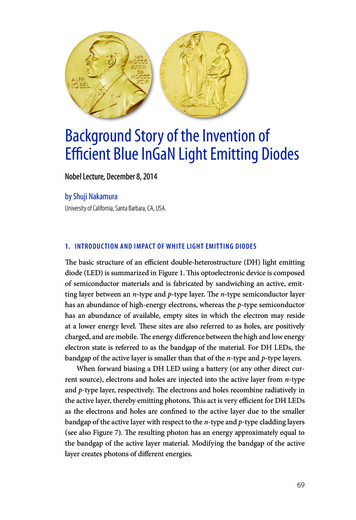
Background Story of the Invention ofEfficient Blue InGaN Light Emitting DiodesNobel Lecture, December 8, 2014by Shuji NakamuraUniversity of California, Santa Barbara, CA, USA.1. INTRODUCTION AND IMPACT OF WHITE LIGHT EMITTING DIODESThe basic structure of an efficient double-heterostructure (DH) light emittingdiode (LED) is summarized in Figure 1. This optoelectronic device is composedof semiconductor materials and is fabricated by sandwiching an active, emitting layer between an n-type and p-type layer. The n-type semiconductor layerhas an abundance of high-energy electrons, whereas the p-type semiconductorhas an abundance of available, empty sites in which the electron may resideat a lower energy level. These sites are also referred to as holes, are positivelycharged, and are mobile. The energy difference between the high and low energyelectron state is referred to as the bandgap of the material. For DH LEDs, thebandgap of the active layer is smaller than that of the n-type and p-type layers.When forward biasing a DH LED using a battery (or any other direct current source), electrons and holes are injected into the active layer from n-typeand p-type layer, respectively. The electrons and holes recombine radiatively inthe active layer, thereby emitting photons. This act is very efficient for DH LEDsas the electrons and holes are confined to the active layer due to the smallerbandgap of the active layer with respect to the n-type and p-type cladding layers(see also Figure 7). The resulting photon has an energy approximately equal tothe bandgap of the active layer material. Modifying the bandgap of the activelayer creates photons of different energies.69
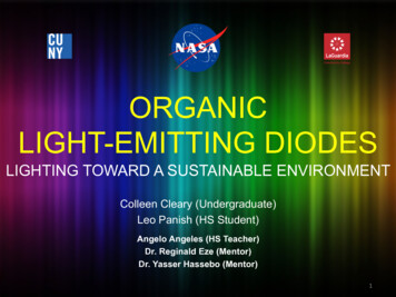
70 The Nobel PrizesFIGURE 1. Schematic depiction of a double heterostructure (DH) light emitting diode(LED) in operation while being powered by a 2.8 V battery. Within the active, emittinglayer, electrons and holes recombine and emit light equal to the bandgap of said layer.High-energy electrons are sourced from the negative terminal of the battery and returnto the positive terminal after losing their energy to a photon in the active layer.In the 1980s, all known material systems possessing the necessary materialproperties for blue light emission had shortcomings negating the possibility ofcreating an efficient blue LED. Gallium nitride (GaN) was one possible candidate, though, at the time, no p-type or active layer could be created. These challenges were ultimately overcome, leading to the first efficient blue LED usingGaN in 1993 by Nakamura et al. [1]. Figure 2 shows a close-up image of a bareand packaged blue GaN LED.Using blue LEDs, highly efficient white light sources become possible. Thiscan be achieved by converting part of the blue light emitted from an LED toyellow using a phosphor [2]. To the human eye, the combination of blue andyellow light is perceived as white. A white LED can be created by embeddingphosphors in a plastic cap which surrounds a blue LED (see Figure 3). Higherquality white light can also be created by mixing blue light with other colors aswell, including red and green [3].With the availability of white LEDs, a variety of applications can be significantly improved, if not enabled all together. But arguably, the most importantimpact of the white LED is its ability to generate white light at an efficiencythat was previously impossible. The efficacy, a measure of perceived light powerrelative to the provided electrical power, of white light has improved over the
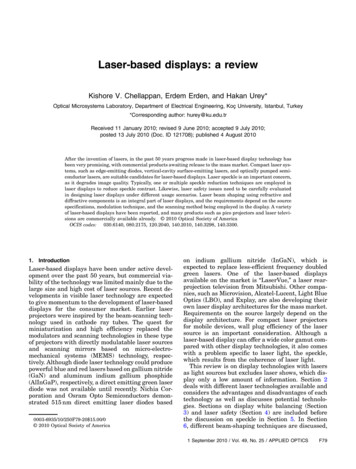
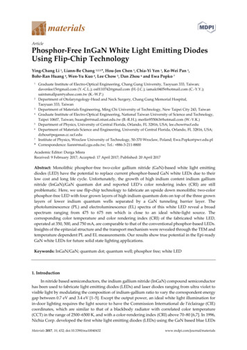
Story of the Invention of Efficient Blue InGaN Light Emitting Diodes 71(a)(b)FIGURE 2. (a) Image of a blue GaN LED with attached gold wire contacts (size of diode:0.4 mm 0.4 mm) and (b) the same LED packaged as a commercial product [1].centuries, starting with oil lamps (0.1 lm/W) in the 15,000s B.C., incandescentbulbs (16 lm/W) in the 19th century, fluorescent lamps (70 lm/W) in the 20thcentury, and LEDs (300 lm/W) in the 21st century (see also Figure 15).With this significant improvement, substantial energy savings are now possible. It is currently estimated that in 2030 approximately 261 TWh of electricalenergy will be saved due to widespread use of white LEDs [4]. This correspondsto an electricity savings of approximately 40% in 2030. Furthermore, this reduction in energy usage eliminates the need for at least 30 1-GW power plants by2030 and avoids generating 185 million tons of CO2.FIGURE 3. From blue LED to white LED. Part of the blue light emitted from a blue LED isconverted to lower energy colors, such as yellow, using a phosphor. The combination ofblue and yellow light is perceived as white to the human eye. Combining a blue LED withembedded phosphors in the plastic cap creates a white LED. [3]
72 The Nobel Prizes2. MATERIAL OF CHOICE: ZnSe VS. GaNIn the 1980s, there were two materials considered as possible candidates for efficient blue LEDs: zinc selenide (ZnSe) and GaN [5].ZnSe could be grown on single crystal gallium arsenide (GaAs) substrates,yielding high structural quality material given the very small lattice mismatch of0.3% between ZnSe and GaAs. For GaN, on the other hand, no lattice-matchedsubstrate was available and researchers were forced to grow it on sapphire. Thelarge lattice mismatch ( 16%) resulted in heavily defected material with a highdensity of dislocations.When I joined the field in 1989, ZnSe was grown on GaAs with dislocation densities less than 103 cm–2. It was very popular among scientists, given thehigh crystal quality and the prevailing notion that a dislocation density below103 cm–2 is needed to achieve optically functional LEDs with a high efficiencyand a long lifetime [5]. Most researchers worked in this field. GaN, however,was grown on sapphire, yielding dislocation densities on the order of 109 cm–2.Unsurprisingly, few researchers were working in this field except, most notably,fellow Nobel Laureates Professor Isamu Akasaki and his graduate student at thetime, Hiroshi Amano.A striking example to highlight the popularity of ZnSe, as compared to GaN,is provided by looking at the attendance of researchers at the most popular conference for applied physics in Japan. At the Japan Society of Applied Physics(JSAP) conference in 1992, there were approximately 500 individuals attendingthe ZnSe sessions, whereas for GaN, there were around 5, including the chairProfessor Isamu Akasaki, speaker Hiroshi Amano and myself, as a member ofthe audience. Not only was ZnSe more popular at the time, GaN was activelydiscouraged with researchers stating “GaN has no future” and “GaN people haveto move to ZnSe material.”3. DEVELOPMENT OF GaNMy entry into the field started in April of 1988, when I went to the Universityof Florida as a visiting researcher. The main purpose of my visit was to learnhow to use a MOCVD (Metal Organic Chemical Vapor Deposition) system togrowth GaAs crystals on a silicon substrate, as I had no experience in how to usea MOCVD. During my stay there, I worked together with graduate students andthey all asked me if I had a Ph.D. I said no. At the time, I only had a Master’s.Next, they asked me if I had published any scientific papers. Again, I said no, Ihad never published a single paper. Consequently, they treated me as a technician. In the U.S., this meant one has to help the researcher and one’s name would
Story of the Invention of Efficient Blue InGaN Light Emitting Diodes 73not appear on papers or patents. Gradually, I became very frustrated with thisarrangement.One year later, in March of 1989, I came back to Japan. It was my dream toget a Ph.D. degree. In Japan, at the time, it was possible to be awarded a Ph.D.if one published five scientific papers. This type of degree was called a paperdegree and one did not need to go to the university to get the degree. It wastherefore my ultimate dream to publish at least five papers and get a Ph.D.With this in mind, I noted that the ZnSe field was publishing lots of papers.As I had never published a paper, I had no confidence in publishing a paper. Inthe GaN field, only very few papers had been published, mainly from Professor Isamu Akasaki and Hiroshi Amano. I was therefore confident that I couldpublish lots of papers, though had no confidence that I could actually invent theblue LED. My only objective was to get a Ph.D. That’s it.So, after returning to Japan in March of 1989, I wanted to grow GaN usinga MOCVD reactor. I purchased a commercially available MOCVD reactor for2 million U.S. dollars. But this MOCVD reactor was designed for growth ofGaAs. At the time, Professor Akasaki and his student Amano had developed anovel, research-scale MOCVD reactor for growth of GaN [6]. Their design required exceptionally high carrier gas velocities (around 4.25 m/s) yielding GaN,though the high carrier velocities presented challenges pertaining to uniformity,scalability and reproducibility. Furthermore, their reactor design could only beused for small area growths, thereby lacking the necessary properties for commercialization. Since I was working for a company, I had to find a way to growhigh quality GaN on large area, 2-inch diameter sapphire substrates.Another challenge related to growing high quality GaN was the use of highconcentrations of aluminum in the MOCVD reactor. While the developmentof the aluminum nitride (AlN) buffer layer by Akasaki and Amano was a majorbreakthrough providing high quality GaN film growth with a mirror-like surface morphology [6], the use of aluminum caused significant problems to theMOCVD reactor resulting in poor reproducibility in subsequent GaN growths.Eliminating the use of high concentrations of aluminum during growth wasstrongly desired.After my purchase of a MOCVD reactor, I attempted a significant numberof growths over the course of a few months, but consistently failed. Either nogrowth of GaN occurred or the grown layer was black. GaN should be transparent. I realized this was a big problem, especially considering the substantialinvestment in the tool. That is when I decided I had to modify the reactor.For the next 1.5 years, I modified the reactor design. In the morning, I wouldgo to work and modify the reactor. In the afternoon, I would perform a couple
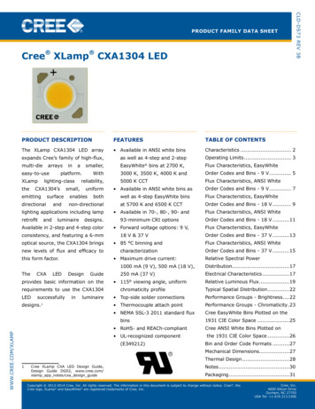
74 The Nobel Prizesof growths and analyze the results. I would repeat this pattern for 1.5 years untilI invented a novel MOCVD reactor design with a low carrier gas flow which Icalled a two-flow MOCVD (Figure 4 a) [7]. Using this reactor, I was able to getvery uniform and high quality 2-inch GaN growth. The main breakthrough ofthis reactor was the introduction of a subflow (Figure 4 b) which gently pushedthe carrier gases down to the substrate, thereby also improving the thermalboundary layer.This was the most important breakthrough in my life and was instrumentaltoward all future breakthroughs in GaN research. One significant advancement(a)(b)FIGURE 4. (a) Schematic of a two-flow MOCVD for GaN growth and (b) schematic of theeffect of the newly introduced subflow on the carrier gases. [7] (Reprinted with permission. Copyright 1991, AIP Publishing LLC.)
Story of the Invention of Efficient Blue InGaN Light Emitting Diodes 75this tool immediately enabled was the development of a GaN buffer layer whichwas superior to the AlN buffer layer, in part due to the elimination of aluminumfrom the growth system. With the invention of the two-flow MOCVD and theGaN buffer layer, it was possible to achieve the highest quality GaN material inthe world. One measure for crystal quality is the value of the electron mobility ina crystal. Fewer defects result in fewer scattering events, which enhances overallmobility of the electrons. Mobilities for GaN grown directly on sapphire (nobuffer layer) by Akasaki and Amano resulted in values around 50 cm2/Vs [6],whereas use of the two-flow MOCVD yielded 200 cm2/Vs [7]. Use of an AlNbuffer layer improved the mobility to values as high as 450 cm2/Vs for Akasakiand Amano [8]. Use of a GaN buffer layer and the two-flow MOCVD valuesas high as 600 cm2/Vs were measured at room temperature (see Figure 5) [9].This was a clear sign that the two-flow MOCVD was producing GaN material ofhigher quality on larger area substrates, a key step towards commercializationof GaN based devices.The next significant development in creating an efficient blue LED occurredin 1992 when I was able to clarify why p-type GaN had remained so elusivefor 20 years. While Akasaki and Amano achieved a major breakthrough in1989 by demonstrating local p-type GaN after treating magnesium doped GaN(GaN:Mg) with low-energy electron beam irradiation (LEEBI) [10], its originFIGURE 5. Hall mobility measurements at 77 K ( ) and 300 K ( ) for a 4 μm thick GaNfilm grown on sapphire as a function of the GaN buffer layer thickness. [9] (Reprintedwith permission. Copyright 1991, The Japan Society of Applied Physics)
76 The Nobel Prizeswas not understood for another three years. In 1992, I clarified that hydrogenwas the source of passivating p-type GaN [11]. A few years later, theoreticalcomputations by Jörg Neugebauer and Chris Van de Walle confirmed hydrogenpassivation in Mg-doped GaN [12].For MOCVD growth of GaN, ammonia (NH3) is used as the nitrogensource. Ammonia dissociates during growth and atomic hydrogen is introducedinto the GaN crystal. If Mg is present in the crystal, the hydrogen atom forms amagnesium hydrogen complex (Mg-H), thereby preventing Mg from acting asan acceptor [11]. Thermal annealing of the GaN:Mg sample in a hydrogen-freeenvironment above approximately 400 C permits hydrogen to diffuse out ofthe crystal, thereby breaking up the Mg-H complex [13]. As thermal annealingcan be performed quickly and simultaneously on multiple substrates of any sizein parallel (an act not achievable using LEEBI), it has become the industrialstandard process for p-type activation of GaN. The formation of local p-typeGaN using LEEBI treatments can be explained by local heating of the GaN:Mgby the electron beam, causing the hydrogen to locally diffuse out of the crystaland permitting the affected Mg atoms to act as acceptors yielding p-type GaN.With the ability to grow n-type and p-type GaN, p-n homojunction LEDs(DH LEDs lacking an active layer) can be formed. The first p-n homojunctionLED was demonstrated by Amano et al. in 1989 using an AlN buffer layer and(a)(b)FIGURE 6. (a) Change in electrical resistivity of as grown Mg-doped GaN films as a function of annealing temperature in a nitrogen environment [13]. (b) Change in resistivity ofLEEBI-treated Mg-doped GaN films as a function of annealing temperature in a nitrogen( ) or ammonia ( ) environment [11]. Annealing time was 20 min for all samples. (Reprinted with permission. Copyright 1992, The Japan Society of Applied Physics)
Story of the Invention of Efficient Blue InGaN Light Emitting Diodes 77their newly developed LEEBI treatment process to obtain p-type GaN [10]. Theyreported on the observed current-voltage (I–V) relationship and electroluminescence (EL) of the manufactured LEDs, but did not mention the output poweror the efficiency of the LEDs. In 1991, Nakamura et al. demonstrated a p-nhomojunction GaN LED using a low-temperature GaN buffer and the LEEBItreatment [14]. The output power at 20 mA with a forward voltage of 4 V was 42µW. The external quantum efficiency (EQE) and peak emission wavelength were0.18% and 430 nm, respectively.For LEDs to be useful for real world applications, the light output powerneeds to be well in excess of 1 mW. P-n homojunction LEDs cannot reach thoselevels of output power without generating substantial amounts of waste heat, inlarge part due to the inefficient device structure. Additionally, p-n homojunction LEDs produce light of a fixed wavelength given the exclusive use of GaN,which has a fixed bandgap. In spite of the achievement by Akasaki and Amanoto produce optically active GaN p-n homojunction LEDs, Toyoda Gosei Co.,Ltd. issued a press release for production of Metal-Insulator-Semiconductor(MIS) GaN LEDs with an output power of 70 µW on October 20, 1993 [15].MIS type LEDs use a semi-insulating layer instead of a p-type layer and are alsoa relatively inefficient device design. The complete omission of p-type GaN isadvantageous though, as it sidesteps various challenges associated with largearea p-type activation using the LEEBI process.Arguably the most efficient LED designs make use of a DH. The concept andinvention of the heterostructure in semiconductor materials was so significantthat it earned the Nobel Prize in Physics for Zhores Ivanovich Alferov and Herbert Kroemer in 2000. The energy band diagram is shown in Figure 7 for the p-nhomojunction LED and the DH LED.(a)(b)FIGURE 7. Schematic energy band diagram structure for a (a) homojunction LED and (b)double heterostructure LED.
78 The Nobel PrizesIn order to understand the advantage a DH LED provides over a p-n homojunction LED, one needs to look at the internal quantum efficiency (IQE) (seeEquation (1)).IQE Light generatedRradiativeBn 2 Electrons injected Rradiative Rnon radiative An Bn 2 Cn 3(1)The IQE is a measure of efficiency and is related to how many electrons areconverted into photons within the active region. There are three mechanisms bywhich a high-energy electron may decay to a lower energy state. One of themis a radiative process (Rradiative, emission of a photon, desired), while the othertwo are non-radiative (Rnon-radiative, emission of phonons, i.e. heat, undesired)and include the Shockley-Read-Hall (SRH) process and Auger recombinationprocess. All of these processes are dependent on the minority carrier concentration (electrons in a p-type layer, holes in a n-type layer), n. The SRH processincreases linearly (A n), the radiative recombination process quadratically (B n2), whereas the Auger recombination process increases as the cube (C n3) of n.The coefficients A, B and C are constants.For low carrier concentrations, the SRH term (A n) dominates, leading topoor efficiencies and significant non-radiative recombination. This is the casefor p-n homojunction LEDs. Due to the p-n structure of the LED, electrons diffuse into the p-type layer and holes diffuse into the n-type layer. The diffusionlength of minority carriers in GaN is approximately 1 µm [16]. This causes carriers to be spread out over a large region reducing their concentration. The DHLED, on the other hand, confines the carriers to within the active layer, which istypically around 3–200 nm thick. This confinement significantly increases theirconcentration under the same current density and enhances the probability ofradiative recombination (B n2), thereby increasing the efficiency of the LED.4. DEVELOPMENT OF InGaN4.1 InGaN based devicesAchieving a high quality active layer with the necessary properties to form a DHLED is the last and, arguably, the most critical, step towards achieving a commercializable and efficient LED. Indium gallium nitride (InGaN) was identified asthe ideal candidate for the active layer. Through addition of indium into the GaNcrystal, the electrical bandgap of the material shrinks, thereby providing boththe ability to confine carrier in a DH arrangement, but also provide the ability totune the color of the light by changing the amount of indium in the InGaN alloy.
Story of the Invention of Efficient Blue InGaN Light Emitting Diodes 79Despite this realization, high quality layers of InGaN could not be realizedin the 1970s and 1980s. Room temperature (RT) band-to-band emission, essential for the active layer of a DH LED, could not be achieved given the defectivenature of the material.The reason for this can be traced back to the many challenges associatedwith InGaN growth, which is in many ways more challenging to grow thanp-type or n-type GaN. Indium has such a high vapor pressure, that at typicalgrowth temperatures of GaN ( 1000 C), it would boil off the surface and notincorporate into the crystal. Growth at lower temperatures yielded poor crystalquality along with numerous defects and impurity incorporation. Growths atintermediate temperatures required uniform and stable growth temperatures,as the incorporation of indium is strongly dependent on the temperature, witha few degrees differences across the substrates resulting in noticeable variationsin output color across the wafer.Furthermore, in order to effectively use InGaN in a DH LED, excellent control over the various growth parameters is required, as the interface betweenGaN and InGaN needs to be smooth on an atomic level. In addition to a smoothsurface morphology, the MOCVD reactor requires precise control over allgrowth parameters and superior uniformity across the entire surface to achieveexceptionally thin layers of high quality (a layer is typically composed of a few10s to 100s of atom layer thicknesses in DH LEDs). To make matters even morechallenging, introduction of indium into the GaN lattice results in significantstrain since indium is roughly 20% bigger in size than gallium. Managing thisstrain and preventing the formation of defects within the layer is important.The first recorded InGaN alloy growth was performed by electron beamplasma in 1972 and 1975 by Osamura et al. on sapphire and quartz substrates[17,18]. In 1989, Nagatomo et al. grew InGaN on a sapphire substrate usingMOCVD at a growth temperature of 500 C [19]. In 1991, Yoshimoto et al. demonstrated growth of InGaN layers at a growth temperature of around 800 Cusing MOCVD [20]. Despite this achievement, their crystal quality was poor asevidenced by their RT photoluminescence (PL) exhibiting only deep level emission (no band-to-band emission) (Figure 8) and by a full width at half maximum (FWHM) of the double crystal X-ray rocking curve (XRC) of 30 arcmin.In 1992, Mukai and myself succeeded in growing a high quality InGaNlayer using the two-flow MOCVD on a GaN template grown on a sapphiresubstrate [21]. RT PL showed a strong band-to-band emission from violet toblue depending on the indium composition of the InGaN layers. This was thefirst report of band-to-band emission of InGaN layers at RT. The FWHM of thedouble crystal XRC was around 8 arcmin. Figure 9 shows the first observation
80 The Nobel PrizesFIGURE 8. Photoluminescence spectra of In0.235Ga0.765N grown at 800 C using MOCVDon a sapphire substrate by Yoshimoto et al. [20]. (Reprinted with permission. Copyright1991, AIP Publishing LLC.)of band-to-band emission of the InGaN layers at RT described in reference [21].With this demonstration, the last remaining barrier for efficient blue LEDs wasovercome opening the doors for rapid development of high brightness, highpower, high efficiency blue LEDs using the DH structure.Building on this success, I immediately investigated embedding these InGaN layers within a DH LED structure. The first demonstration of a blue DHLED occurred in 1993 with a p-GaN/n-InGaN/n-GaN structure [22]. The activelayer was a Si-doped InGaN layer with a thickness of 20 nm. The LED showedstrong band-edge emission in the InGaN layer yielding blue light with a wavelength of 440 nm under forward bias conditions. The output power and the EQEwere 125 µW and 0.22%, respectively, at a forward current of 20 mA.Further improvements to the device led me to demonstrate in 1994 the firstcommercially available blue LED with an output power of 1.5 mW, an EQE of2.7% and the emission wavelength of 450nm (Figure 10) [23]. The structure ofthis DH LED was p-GaN/p-AlGaN/Zn-doped InGaN/n-GaN. The Zn-dopedInGaN active layer had a thickness of 45 nm and was used due to an observedincrease in luminous efficiency. For the first time, an electron-blocking layerwas introduced into the structure. The p-AlGaN prevented electrons from overflowing the electron confinement provided by the active layer, further enhancing radiative recombination.Simultaneously with my publication, Nichia Chemical Corporation releaseda press statement mentioning production of high brightness blue DH LEDs withp-type layers, an output power of 1.5 mW and a brightness of more than 1000
Story of the Invention of Efficient Blue InGaN Light Emitting Diodes 81(a)(b)FIGURE 9. (a) RT PL spectra of InGaN films grown on GaN films under identical growthconditions, except for the InGaN growth temperatures of 830 C (trace (a)) and 780 C(trace (b)). (b) Change in peak wavelength of PL spectra as a function of indium molefraction (x) in InxGa1–xN films. Indium fraction was determined by X-ray diffractionmeasurements. [21] (Reprinted with permission. Copyright 1992, The Japan Society ofApplied Physics).mcd (roughly equal to the luminous intensity of 1 candle) on November 30,1993 [24]—just one month after the press release about MIS type LEDs withan output power of 70 µW by Toyoda Gosei Co. Ltd on October 20, 1993 [15].Further improvements to the growth conditions allowed me to demonstratehigh brightness blue, green and yellow LEDs with InGaN quantum well (QW)
82 (a)The Nobel Prizes(b)FIGURE 10. (a) Structure of InGaN/AlGaN double-heterostructure blue LED with (b) resulting output power as a function of forward current. [23] (Reprinted with permission.Copyright 1994, AIP Publishing LLC.)structures in 1995 (see Figure 11) [25]. QW structures are DH structures witha very thin active layer, so thin that quantum confinement effects need to beconsidered. Layer thicknesses for QW structures are on the order of a few nanometers (a few atom layer thicknesses) versus 100 nm for typical DH structuresup to this point. This thinning further improves the IQE due to higher carrierconcentrations, but also requires even more stringent controls on uniformityand temperature during MOCVD growth.Further improvements to growth conditions of the InGaN layers led to theavailability of higher power blue and green single QW (SQW) LEDs. At a 20mA current, the output power and the EQE of the blue SQW LEDs were 5 mWand 9.1%, respectively. Those of green SQW LEDs were 3 mW and 6.3%, respectively. The structure of the green SQW LED and output powers of the blue,green and yellow SQW LEDs are shown in Figure 11 [26]. This LED epitaxialstructure is still the basic foundation for all currently commercially availableblue and green LEDs.With the success of the developed high efficiency, high power blue LED,Nichia Chemical Corporation commercialized the first white LEDs by combining the blue InGaN QW DH LED [25, 26] with a yellow yttrium aluminumgarnet (YAG, Y3Al5O12) based phosphor [27].Having excelled at achieving high efficiency blue LEDs, the next step for mewas to demonstrate the first InGaN-based laser diode. I achieved this in 1996under pulsed [28] and continuous wave (CW) [29] operations. Figure 12 showsthe device structure and light output power versus current (L–I) curve for the
Story of the Invention of Efficient Blue InGaN Light Emitting Diodes 83(a)(b)FIGURE 11. (a) Green single quantum well (SQW) LED structure. (b) Output power of ablue, green, and yellow SQW LED at RT as a function of forward current. [25, 26] (Reprinted with permission. Copyright 1995, The Japan Society of Applied Physics)first InGaN-based laser diode [28]. The structure was composed of an InGaNmulti-quantum wells (MQW) active layer, GaN waveguide layers and AlGaNcladding layers.4.2 Material Properties of InGaNOne mystery still remains to date, namely why InGaN materials are atypicaland luminesce with such high efficiency despite the high density of dislocations.It was deemed common sense in the 1980s that highly efficient LEDs with along lifetime required dislocation densities less than 103 cm–2. Despite all the
84 The Nobel Prizes(a)(b)FIGURE 12. (a) Structure of a violet InGaN MQW laser diode with (b) corresponding L–Icharacteristics indicating the onset of lasing (30 μm wide, 1500 μm long) [28] (Reprintedwith permission. Copyright 1996, The Japan Society of Applied Physics).improvements in MOCVD growth of GaN, the fundamental lattice mismatchbetween sapphire and GaN remains, yielding 109 cm–2 dislocations in the GaNand InGaN layers, even for the high efficiency devices demonstrated in the1990s. To highlight the stark difference between InGaN and other semiconductors, Figure 13 depicts the approximate dependence of the LED efficiency onthe dislocation density for various semiconductor materials. As can be seen,highly efficient arsenide and phosphide based LEDs could only be achieved fordislocation densities below 103–105 cm–2. This observation led to the erroneous statements that dislocation densities below 103 cm–2 are needed for efficientLED operation. Pure GaN LEDs behave comparably to the other arsenide andphosphide LEDs, as demonstrated by dim p-n GaN homojunction LEDs developed by Akasaki and Amano in 1989 [10]. Interestingly, InGaN materials
Story of the Invention of Efficient Blue InGaN Light Emitting Diodes 85FIGURE 13. Dependence of LED efficiency on dislocation density for various semiconductor materials. (After [30,31,32])behave quite differently, exhibiting high efficiencies despite high dislocationdensities [30].One explanation for this phenomenon, as proposed by Professor Chichibufrom Tohoku University, is the presence of localized states in the InGaN layer[31, 32]. When electrons and holes are injected into the active layer, they arecaptured by localized states within the layer and radiatively recombine beforethey are captured by crystal defects (dislocations), which would provide nonradiative recombination pathways. The localized centers can be thought of asenhanced emission centers of light.Localized states may emerge due to the natural fluctuation of indium withinthe InGaN layers. Atom probe tomography measurements of the InGaN layershave provided atomic level resolution of the chemical and spatial distribution ofatoms within the layer (see Figure 14) [33]. The statistical analysis of the indiumdistribution in the layer yields a random binomial distribution on the Group IIIsite about some av
creating an eˆcient blue LED. Gallium nitride (GaN) was one possible candi-date, though, at the time, no p-type or active layer could be created. ese chal-lenges were ultimately overcome, leading to the rst eˆcient blue LED using GaN in 1993 by Nakamura eal.]e 2 shows a close-up im