Transcription
Data Communications ProductsASrASTCC-432RESEAACH INC.Communications Hardware Product Providing aSynchronous Communications Channel Normaland NRZI Data Encodingand Security for Custo;mized SoftwareJ
CC·432 Advanced Communication Boardfor theIBM Personal Computer,and IBM PC·XTUser's Manual000140-001 DOctober 1985AST RESEARCH, INC.Irvine, California(714) 863-1333
Fourth Edition (October 1985)IBM is a registered trademark of International Business MachinesCorporation.MOSTEK is a registered trademark of Mostek Corporation.Z-80 is a registered trademark of Zilog, Inc.Compaq is a trademark of Compaq Computers, Inc.AST Research periodically changes the information in this manual; changesare incorporated into new editions. AST Research reserves the right tomodify this product's design.A Product Comment Form is provided at the back of this publication. If thisform has been removed, please address your comments to: AST Research,Inc., Attn: Product Marketing, 2121 Alton Avenue, Irvine, CA 92714. ASTResearch may use or distribute any of the information you supply in any wayit deems appropriate without incurring any obligations whatsoever.Copyright 1983 AST Research, Inc. All rights are reserved, including thoseto reproduce this book or parts thereof in any form without permission inwriting from AST Research, Inc.WARNINGThis manual is protected by United States Copyright law(Title 17 United States Code). Unauthorized reproductionand/or sales may result in imprisonment of up to oneyear and fines of up to 10,000 (17 USC 506).Copyright infringers may be subject to civil liability.
TABLE OF CONTENTSSECTION 1 INTRODUCTION.1.1PC Compatibility .1.2 Modem Compatibility . . . . . . . . . . . . . . . . . . . . . . . . . .1.3 Related Documentation . . . . . . . . . . . . . . . . . . . . . . . .1-11-11-21-2SECTION 2 CONFIGURATION . . 2-12.1Factory Default Configuration . 2-22.2 Cable Information . 2-22.3 Changing the Factory Default Configuration . 2-42.4 I/O Address and Function Selection . 2-42.5 Port Configuration . 2-72.6 Interrupt Line Selection . 2-92.7 Baud Rate Selection . 2-102.8 CC-432 Shorting Plug Summary . 2-102.9 Additional Control Signals . 2-122.10 NRZI Encode/Decode . 2-13SECTION 3 INSTALLATION . . 3-1SECTION 4 PROBLEM DETERMINATIONPROCEDURES . .4.1Finding the Problem .4.1.1 Modems .4.1.2 Software Parameters .4.1.3 Phone Lines .4.1.4 PC System Hardware .4.2 Repair Procedure .4-14-14-14-24-24-24-3SECTION 5 THE C432TEST DIAGNOSTIC .5.1Hardware Requirements .5.2 Software Requirements .5.3 Setup .5.3.1 CC-432 Board Setup .5.3.2 Loopback Plug Configuration .5.3.3 Install the Modem or Loopback Plug .5.4 Diagnostic Operation .5-15-15-25-25-25-45-45-4iii
TABLE OF CONTENTS(Continued)5.5 Test Descriptions .5.5.1 SIO Register Write/Read Test .5.5.2 SIO Interrupt Test .5.5.3 SDLC Loopback Test. .5.6 Error Messages .5-65-65-75-75-7APPENDICESAPPENDIX A 110 ADDRESS MAP . A-1APPENDIX B HARDWARE INTERRUPT LINES . 3-1.3-2.3-3.3-4.3-5.CC-432 Board Layout .Turn PC Power OFF (rear view) .Remove PC Cover .IBM Expansion Slots .Install Your CC-432 Board .Install Cables .2-63-23-33-43-53-6TABLESTable 2-1. CC-432 (DTE mode) andModem Configuration . 2-3Table 2-2. CC-432 110 Address Select . 2-5Table 2-3. CC-432 AO-A3 Function Select . 2-7Table 2-4. DTE and DCE Configurations . 2-8Table 2-5. SIO Data and Modem Control Signals . 2-8Table 2-6. Interrupt Line Selection . 2-9Table 2-7. CC-432 Shorting Plug(Positions 1-9) Summary . 2-10iv
SECTION 1INTRODUCTIONThis manual tells you how to configure, install, and run thediagnostic for the AST Research, Inc., CC-432 AdvancedCommunication board. The CC-432 board allows you toconfigure its single-channel communications port as DTE(Data Terminal Equipment, the equipment associated with auser) or DCE (Data Communications Equipment, theequipment associated with the transmission facilities). TheCC-432 board performs all serial-to-parallel and parallel-toserial conversions in synchronous mode, and offers a choiceof normal or Non Return to Zero Inverting (NRZI) dataencoding.The combination of the CC-432 board and AST Researchcommunications packages provides convenience and costsaving by allowing you to support a variety of terminalemulation and communications protocols. To use a differenttype of emulation or communication capability, simply changediskettes and boot another AST Research communicationsprogram.The communication element on the AST Research CC-432board is its dual port Serial Input/Output (SIO) chip. Thefunctions available on the SIO include modem control signalsand CRC (Cyclic Redundancy Check) error checking.1.1 PC CompatibilityThe AST Research CC-432 Advanced Communication boardis completely compatible with the IBM PC and PC-XT.1-1
1.2 Modem CompatibilityThe CC-432 board and its various associated AST Researchsoftware packages are designed for use with Bell-compatiblesynchronous modems. A Bell-compatible modem usually hasa model number that corresponds to the Bell standard itcomplies with, and different model numbers operate atdifferent baud rates (for example, 212 1200 baud,201 2400 baud, and 208 4800 baud).You can use other modems as long as the modems at bothends of the phone line are compatible with each other. Themodem that you use must also be compatible with themodem at the host (the host is the machine that you arecommunicating to). For example, if you use an IBM modem ata host computer, you must use an IBM modem at an IBM PCat the other end of the phone line. An IBM modem will notcommunicate with a Bell-compatible modem.All AST Research emulation package line protocols requiresynchronous modems. Asynchronous modems (such as theHayes and Novation modems) will not work with ASTResearch emulation packages.1.3 Related DocumentationThis manual assumes some familiarity with the PC-DOSoperating system and the PC hardware. This information canbe found in the following manuals:IBM Personal Computer Guide to Operations manualIBM Personal Computer Technical Reference manualIBM Personal Computer Disk Operating System manual1-2
The communication element of the AST Research CC-432Advanced Communication board is the 510 (such as the ZilogZ-80 510-0 or the MOSTEK MK3884). Programming andvector interpretation of the 510 are detailed in an 510reference manual such as:Zilog Z-80 SID Technical ManualorMOSTEK MK38841517 Serial 110 Controller Technical Manual1-3
1-4
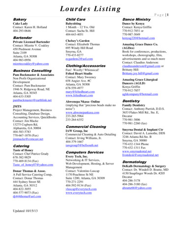
SECTION 2CONFIGURATIONIf your CC-432 board is part of a complete AST Researchhardware/software package,and you intend to communicatewith a host computer via a modem/phone line link, it -isprobably ready to use in its factory default configuration.NOTEIf you are using the AST-3780 package, theCC-432 board is ready to use as is (verifythe factory configuration below). If you areusing the AST-5251, AST-SNA, or AST-BSCcommunications packages, the only changeyou have to make to the factoryconfiguration is to remove the shorting plugfrom pOSition 8.Otherwise, you must configure the AST Research CC-432Advanced Communication board to select its IBM PC I/Oaddresses, interrupt line, baud rate, and to configure itscommunications port as DCE or DTE (default is DTE). Youcan also configure your CC-432 to take advantage ofadditional control signals, and to support the Non Return toZero Inverting (NRZI) data encoding that is commonly usedwith some synchronous protocols (default is non-NRZI).This section describes how to set the DIP switch, shunts, andshorting plugs for your application, and is intended primarilyfor those users who want to create their own custom softwarefor the CC-432. If you are using the CC-432 as part of acomplete AST Research communications package, thisinformation is useful as a reference. Your AST Researchcommunications package user's manual tells you how toconfigure your CC-432 board for your application.2-1
NOTEWhen you install your AST Researchcommunications package and CC-432 cardin your PC, be sure that you know whichIRQ lines and I/O addresses are used byeach of the devices in your system (youcan obtain this information from the devicesuppliers, user's manuals, and your dealer).Resolving device conflicts before installationwill save time and frustration later on.Refer to the CC-432 board layout (Figure 2-1) throughout thissection.2.1 Factory Default ConfigurationIf your CC-432 board is part of a complete AST Researchhardware/software package (such as AST-SNA, AST-BSC,AST-3780, or AST-5251), it is probably ready to use in itsfactory configuration, and you won't need to make anychanges.To verify proper factory default configuration, check yourCC-432 board settings:1.DIP switch SW1 set as follows:12345678ON ONOFF OFF OFF OFF OFF ON2.DIP shunts installed in positions U25 and U27 (DTE).3.Shorting plugs installed in positions 1, 3, and 8.2.2 Cable InformationThis Subsection gives cable configuration information that isimportant for standard use.2-2
When you use the CC-432 in DTE mode, the cable shouldonly be as long as necessary to reach a modem positionednext to your PC. When you use the CC-432 in DCE mode,limit the cable length to a maximum of 50 feet. Someinstallations require a shielded cable for reliable operation.AST Research recommends that you use a shielded 25-pincable for reliable operation. However, the 11-pin cable shownin Table 2-1 can be used for some installations; this typicalconfiguration includes the CC-432 board (DTE mode) and asynchronous modem for use with an AST Researchcommunications package (asynchronous modems will not work).Table 2-1. CC-432 (DTE mode) and Modem ConfigurationCC-432J1 PinSignalDirectionModemPinSignal Name1Chassis Ground2Transmit Data (TxD)3Receive Data (RxD)44Request To Send (RTS)55Clear To Send (CTS)66Data Set Ready (DSR)77Signal Ground88Data Carrier Detect (DCD)1515Transmit Clock (TxDCE)1717Receive Clock (RxDCE)2020Data Terminal Ready (DTR)23""'NOTEFor DCE operation, the cable configurationis the same, but the signal directions arereversed.2-3
2.3 Changing the Factory Default ConfigurationIn its factory default configuration the CC-432 board is set upas follows:1.Occupies PC 1/0 hexadecimal addresses 300-30F2.DTE operation (external synchronous modemrequired)3.Interrupts generated on IRQ2.Your AST Research communications package user's manualtells you how to configure your CC-432 board for yourapplication. This information is useful for technical personnelin the event that there is a hardware or software conflictbetween the CC-432 and another device installed in your PC:To reconfigure the CC-432 for a different set of 1/0addresses, refer to Subsection 2.4.To reconfigure the CC-432 for DCE mode, refer toSubsection 2.5.To reconfigure the CC-432 to use an interrupt other thanIRQ2, refer to Subsection 2.6.This section also includes information on the cableconfiguration, baud rate, shorting plug functions,additional modem control signals, and NRZI dataencoding (see Subsections 2.7 through 2.10).2.4 I/O Address and Function SelectionThe CC-432 occupies 16 consecutive locations of the IBM PC1/0 address space. To avoid conflict with existing IBM PCperipheral boards, use an address range that is not used byany of the peripherals in your PC (Appendix A gives thestandard 1/0 address map for the IBM PC). Positions 1 and 2on DIP switch S1 select the 1/0 address range for the CC-432(Table 2-2).2-4
Table 2-2. CC-432 1/0 Address Select12Hexadecimal1/0 F360-36FS1 PositionNOTE*The factory default setting for the CC-432board is for 1/0 addresses 300-30F.AST Research communications packagesnormally use 1/0 addresses 300-30F (S1positions 1 and 2 ON). Consult your user'smanual for information on other availableaddress settings where applicable.2-5
N enFactory Configuration:Shorting Plugs at1,3, and 8Shunt positions for oTE(Factory configuration:shunts Installed atU25 and U27)"'T1cO's:::::;N. oo.1: 0Co)NOJoella.U28 11C) c-J- U3I -- (II ic :su.'----- -r---- t - -oCER6ShuntPositionsU",CC'432j ,U2'.g '------------' , !---- SPI ct :- 1 O'i - 2 :: :3! r-ell' os:::::tEdge ConnectorFactory Configuration: 1, 2, 8 ON (300-30F)CardBracket
Once the CC-432 board has been software-selected, addresslines AO through A3 select the functions summarized inTable 2-3.Table 2-3. CC-432 AO-A3 Function SelectA30000011Address LinesA2A1AO0000101001XXX0101XXXSelected FunctionData port 510 channel AData port 510 channel BControl port 510 channel AControl port 510 channel BReservedReservedRead interrupt vectorX Don't CareIf the selected I/O address range is 300 through 30F, then3nO is 300, 3n1 is 301, and so on. Hexadecimal I/Oaddresses 3nO through 3n3 select one of the 510 registersand perform a read or write (depending on the I/Oinstruction). The 510 contains eight registers (WRO throughWR7) that are programmed by the system program anddetermine the functional personality of the 510 channels (the510 reference manual provides detailed programminginformation).2.5 Port ConfigurationThe communications port on the AST Research CC-432 boardcan be configured as DTE or DCE. In DTE mode: the CC-432expects to be connected to a synchronous modem thatprovides clocking signals as well as data. In DeE mode: theon-board modem eliminator is enabled. For some applicationswhere the PC is in the same room as the host computer, theon-board CC-432 modem eliminator can replace a separatemodem eliminator. The CC-432 modem eliminator does notreplace the RS-232 interface that is required forcommunicating with the PC.2-7
The eight-position shunts that configure the port. also carrysignals that can be used for modem controls. Install theshunts in the positions (shown in Figure 2-1) summarized inTable 2-4 for the desired configuration.Table 2-4. DTE and DCE ConfigurationsConfigurationShunt PositionsDCEDTE*U26, U28U25, U27*The factory default configuration is for DTE operation.Table 2-5 summarizes how the SIO data and modem controlsignals appear at the DB-25 connector in the DTE and DCEconfigurations.Table 2-5. SIO Data and Modem Control SignalsDTE ModeSIO SignalJ1 SignalJ1 PinTxDA OutputRxDA InputRTSA OutputCTSA InputDCDA InputCTSB InputDTRA OutputTxCA InputRxCA InputChassis GroundSignal GroundTxDRxDRTSCTSDCDDSRDTRTxCRxC23458620151717DCE ModeJ1 Signal J1 ***17* In DCE mode, the SIO RTSA output is routed to SIOCTSA input.**In DCE mode, J1 pin 4 RTS input is routed to J1 pin 5CTS output and to SIO DCDA input.***In DCE mode, the J1 pins 15 and 17 clock outputs andSIO clock inputs are determined by the strapping of thebaud rate jumpers as long as shorting plugs areinstalled in positions 2 and 4.2-8
2.6 Interrupt Line SelectionPositions 3 through 8 on DIP switch S1 select an InterruptRequest (IRQ) line for the CC-432. Table 2-6 lists the IRQ lineselected by each of these five positions. An ON conditionselects the interrupt line, and only one IRQ position can beON at any time.Table 2-6. Interrupt Line SelectionS1 PositionInterrupt Line876IRQ2IRQ3IRQ4IRQ5IRQ6IRQ7543NOTEAST Research communications packagesnormally use IRQ2. Consult your user'smanual for information on other availableinterrupt options where applicable.For all applications, make sure that theselected IRQ line is not used by anothersystem device. Only one IRQ position onthe CC-432 can be ON at any time.Appendix B lists standard IBM assignedIRQ applications.When you operate the CC-432 board with the SIO in thevectored interrupt mode and there is an interrupt from theSIO, you must read I/O address 3nF during the interruptroutine. The contents of that address tell you what conditioncaused the interrupt (that is, which of the eight interruptservice routines is pOinted to). This vector must be read in theinterrupt service routine regardless of whether the vectorinformation is used. Failure to read this value can causeimproper SIO interrupt operation. The SIO reference manualdetails programming and vector interpretation.2-9
2.7 Baud Rate Selection (DCE mode only)NOTEIf your CC-432 board is configured for DTEoperation, the position of the baud rateshorting plug has no effect because thebaud rate is determined by the modem.If your CC-432 board is configured for DCE operation, thebaud rate jumper block (shown in Figure 2-1) selects the baudrate for the CC-432 clock (as long as shorting plugs areinstalled in positions 2 and 4). To select the baud rate, installa shorting plug in the position that corresponds to the desiredbaud rate. For example, if you want to select a baud rate of9600, install a shorting plug in the shorting block positionlabeled 9600.2.8 CC-432 Shorting Plug SummaryTable 2-7 summarizes the functions that correspond to theshorting plugs installed in positions 1 through 9 (illustrated inFigure 2-1) on the AST Research CC-432 board. The defaultconfiguration is for shorting plugs installed in positions 1, 3,and 8.Table 2-7. CC-432 Shorting Plug (Positions 1-9) SummaryShorting PlugPositionFunctionDTE Mode: Routes J1 pin 17 Receive Clockinput to the SIO RxCA ReceiveClock input.DCE Mode: No function.2-10
Table 2-7. CC-432 Shorting Plug (Positions 1-9) Summary(Continued)Shorting PlugPositionFunction2DTE Mode: Routes the internal baud rategenerator clock to the 510RxCA Receive Clock input.DCE Mode: Same as DTE. Also routessame clock to J1 pin 15Transmit Clock output.3DTE Mode: Routes J 1 pin 15 TransmitClock input to the 510 TxCATransmit Clock input.DCE Mode: No function.4DTE Mode: Routes the internal baud rategenerator clock to the 510TxCA Transmit Clock output,and to the J1 pin 24 TransmitClock input.DCE Mode: Routes the internal baud rategenerator clock to the 510TxCA Transmit Clock input andto the J1 pin 17 Receive Clockoutput.5DTE Mode: No function.DCE Mode: Routes. the J1 pin 24 TransmitClock input to the 510 RxCAReceive Clock input.6DTE Mode: Routes J1 pin 22 Ring Indicatorinput to the 510 DCDB input.DCE Mode: Forces J1 pin 22 Ring Indicatorinto a false state.2-11
Table 2-7. CC-432 Shorting Plug (Positions 1-9) Summary(Continued)Shorting PlugPositionFunction7DTE Mode: Routes J1 pin 25 Test Indicationinput to the SIO DCDB input.DCE Mode: Routes J1 pin 18 Test input tothe SIO DCDB input.8DTE Mode: Performs loopback of J1 pin 25Test Indication input to J1 pin18 Test output.DCE Mode: Performs loopback of J1 pin 18Test input to J1 pin 25 TestIndication output.9DTE Mode: Routes SIO RTSB output to J 1pin 18 Test output.DCE Mode: Routes SIO RTSB output to J 1pin 25 Test Indication output.The Test and Test Indication signals are not defined by theEIA RS-232 standard, but are supported by some IBMmodems.2.9 Additional Control SignalsYou can use the Request To Send (RTS) and Data CarrierDetect (DCD) signals from SIO channel B to control theadditional interface signals summarized in Table 2-7 (seeshorting plug positions 6 through 9).2-12
2.10 NRZI Encode/DecodeThe CC-432 board automatically defaults to NRZI disabled:you need to reconfigure the board only if you want to useNon Return to Zero Inverting (NRZI) transmission mode.However, the CC-432 board can support the NRZI dataencoding method used with some synchronous protocolsthrough a software enable.The SIO channel B DTR (Data Terminal Ready) outputcontrols the NRZI mode of data encoding and decoding.Enter NRZI mode by setting SIO channel B signal DTR true.The CC-432 remains in NRZI mode until the the DTR bit ofchannel B is reset, or until the next hardware reset or powerup condition.If you use the CC-432 as part of an AST Researchcommunications package that supports NRZI, you can enableor disable the NRZI function via program options. Your ASTResearch communications software user's manual tells youhow to implement NRZI if applicable.The following example (using BASIC statements) illustrateshow to enable NRZI:OUTOUT&H3n3,OS&H3n3,&H80;Select SIO Control Channel B, WRS;Turn on DTRBThe following example (using BASIC statements) illustrateshow to disable NRZI:OUTOUT&H3n3,OS&H3n3,0;Select SIO Control Channel B, WRS;Turn off DTRBNOTEIf the selected 1/0 address range is 300through 30F, then 3nO is 300, 3n1 is 301,and so on.2·13
2-14
SECTION 3INST ALLATIONThis section describes how to install your AST ResearchCC-432 Advanced Communications board.The CC-432 board can be inserted in any of the full-lengthexpansion slot receptacles on the PC system board.CAUTIONBe sure that the power is off and that thepower cord is removed from the PC beforeinstalling or removing any equipment.Also be sure that you have set the switch,shunts, and shorting plugs for yourapplications before you install the CC-432board into the computer. Your ASTResearch communications user manual andSection 2 of this manual describe CC-432configuration in detail.3-1
STEP 1Power off your IBM PC, and all the equipment connected to it(Figure 3-1).Turn power switch offFigure 3-1. Turn PC Power OFF (rear view)3-2
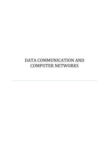
Remove the cover from the IBM PC by removing the coverretaining screws from the computer's rear panel. Slide thecover off, toward the front of the computer (Figure 3-2).NOTENever force the cover forward: if anobstacle inside the PC seems to becatching on the cover, carefully exert anupward pressure along the top-back of thecover until it clears the obstruction.Figure 3-2. Remove PC CoverSTEP 2Select an unused expansion slot, and locate the metalbracket that covers the cutout in the back panel of the PCchassis for the slot that you have selected. Remove and savethe bracket-retaining screw using a small flathead screwdriveror nut driver. Remove the bracket (Figure 3-3).3-3
I"' "' k""''''"'"g ,, .iIIIIOpenExpansionSlotsFigure 3-3. IBM PC Expansion SlotsSTEP 3Arrange the CCA32 board inside the chassis so that its J1connector faces the back of the computer. Align the board'sgold edge connector with the expansion slot receptacle. Usean evenly distributed pressure to press the board straightdown until it seats in the expansion slot (Figure 3-4).3-4
CC-432 BoardFigure 3-4. Install Your CC-432 BoardInstall the bracket-retaining screw that was removed inSTEP 1 to secure the board bracket to the rear of the PCchassis.STEP 4To replace the cover, carefully slide the cover from the frontuntil it stops securely against the rear panel. Reinstall thecover mounting screws you removed earlier.3-5
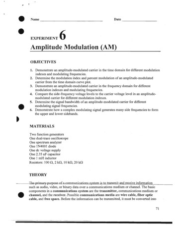
STEP 5Replace the power cord to the system unit and be sure thatthe keyboard and CRT connectors are plugged in. Connectthe serial communications device to the computer by pluggingthe 08-25 connector on the cable into the CC-432 board'sO-shell connector at the back of the computer (Figure 3-5).Monitor PowerCablePower CableKeyboard CableFigure 3-5. Install Cables3-6Serial Cable from CC·432to Serial Device
SECTION 4PROBLEM DETERMINATIONPROCEDURESThis section tells you how to find and solve the most commonproblems that can prevent your CC-432 board fromfunctioning properly, and what to do if your CC-432 boardshould ever require repair.4.1 Finding the ProblemThe following major problem areas can cause your ASTResearch communication package not to function correctly:1.The modem, including: the modem cable, themodem at the PC, and the modem at the hostsystem.2.Software parameters on the AST Researchcommunications package or the host systemcommunications software.3.The phone lines (or other communication lines).4.PC system hardware conflicts, including CC-432board configuration.Modem (especially the cable and the modem at the PC) andsoftware parameter problems are the most common.4.1.1 ModemsBe sure to use synchronous modems with AST Researchterminal emulation software packages: asynchronous modems(such as the Hayes or Novation) will not work. AST Researchpackages require a minimum of 11 signals (for DTE and DCEoperation) to pass through the modem cable to the CC-432 onpins 1 through 8, 15, 17, and 20.4-1
Most modems also have internal switches and jumpers thatyou may have to set: consult the manufacturer's instructionsfor correct configuration, and the suitability of specificmodems and transmission rates for your local telephonesystem. If you suspect that your modem is limiting yourcommunications capability, your modem supplier is the bestsource of information and technical assistance.4.1.2 Software ParametersYour PC software parameters must match the host systemparameters. Your AST Research terminal emulation packagedocumentation or configuration software gives the applicableparameters in detail.4.1.3 Phone LinesYou must tell the phone company (or companies) whatmodem you attach to your phone system. If you want tocommunicate through a PBX-type phone system (used inmany offices), you will need an "exclusion key" or aseparate, direct outside line. Your local phone company andPBX supplier can help you to determine your needs. Be surethat the modem is compatible with your phone system: somemodems require a special phone jack to insure properfunction (signal strength and data integrity).4.1.4 PC System HardwareImproper PC system configuration (including the CC-432board) can prevent your AST Research software packagefrom functioning correctly. The IBM Personal ComputerTechnical Reference Manual and Guide to Operations tell youhow to configure your PC correctly. Your AST Researchcommunications product user's manual and Section 2 of thismanual tell you how to configure your CC-432 board for yourapplication.4-2
4.2 Repair ProcedureIf your AST Research product ever requires repair, contactyour dealer first. The dealer from whom you originallypurchased the product can usually service the product. If youmust return a hardware product to the factory for service,follow these guidelines to ensure rapid, accurate turnaround:1.Call AST Research Technical Support for a ReturnAuthorization Number (RAN): A technician willdiscuss the problem with you; if factory service isrequired, the technician will give you a ReturnAuthorization Number (RAN). Always refer to theRAN when you return anything for service. ASTResearch will return anything without a RAN to thesender.2.If the product is covered under an AST ResearchWarranty: There is no charge for parts or laborinvolved in the repair. Please include a copy of youroriginal purchase receipt as the proof of date ofpurchase for all warranty repairs.3.If the product is not covered under a warranty:Contact your dealer or AST Research TechnicalSupport for instructions on obtaining service for yourproduct.4.Parts not covered under the warranty: Dealer- oruser- installed parts (such as RAM chips) are notcovered under the terms of the warranty. Dealerinstalled parts are warranted by the dealer; partsthat you install are covered only by the partssuppliers' warranties. If we find that your dealer- oruser-installed parts are defective, we can identifywhich parts are defective, but we will not replaceparts unless you specifically authorize us to do so inwriting when you send the board to us. The partscharges and any applicable labor charges will bebilled COD.4-3
5.Describe the problem and return any relatedaccessories: Please include a brief but explicitwritten description of the problem when you returnyour AST product to the factory for repair. Alsoreturn' any accessories that might relate to theproblem. For example, if the the parallel port doesnot function correctly, be sure to return the parallelport adapter cable with the board.6.Be sure to provide a return shipping address thatUPS can deliver to and include your RAN: UPScannot normally deliver to post office boxes. Referencethe RAN issued to you by AST Technical Support onall correspondence. Securely package all materialsto prevent shipping damage. Shipping charges mustbe prepaid; COOs will not be accepted. Ship thematerials to the following address:AST Research, Inc.Customer Service-RAN xxxx2722 Michelson AvenueIrvine, CA 92715where xxxx is your assigned Return AuthorizationNumber.7.4-4Once your product is repaired, we will return it toyou by UPS or UPS Blue Label service, whichever isappropriate for your geographical location. We willreturn items covered by warranty at our expense.Shipping costs and repair expenses for items notcovered by warranty will be billed COD. If you preferovernight service (UPS Red Label), the shippingcharges will be billed COD. If you want us to shipFederal Express, please give us your FederalExpress account number for billing purposes.
SECTION 5THE C432TEST DIAGNOSTICC432TEST is a standalone diagnostic for the AST ResearchCC-432 communication board. C432TEST tests the board bylooping transmitted data back to the board's receiver throughan external synchronous modem or a loopback plug.C432TEST checks the DCD (Data Carrier Detect) signal, butdoes not check CTS (Clear To Send) or DSR (Data SetReady). This section tells you how to use the C432TEST.COMdiagnostic with the AST Research CC-432 advancedcommunication board (up to and including board revisionlevel ).5.1
CC·432 Advanced Communication Board for the IBM Personal Computer, and IBM PC·XT U