Transcription
Chapter 2Leveraging a DynamicEnvironmentCopyright 2015. John Wiley & Sons, Incorporated. All rights reserved.Let’s switch back to the airplane analogy again. So far we’ve sat down inthe cockpit and talked about the most important gauges and controls. Inseveral cases, we’ve even pushed a few buttons and looked behind a few hidden panels. You now have a greater familiarity with the user interface.In this chapter, we’re going to take the plane for a ride and observe anddiscuss how it works. How does it turn? How fast can it go? And, mostimportant, how do the parts work together? You won’t be able to fly soloafter completing this chapter, but you will gain the experience of applyingspecific instructions, producing specific results, and discussing those results.How does this translate to the AutoCAD Civil 3D software? Civil 3D hasa unique, dynamic environment that is all about leveraging interactions andrelationships. If you capitalize on this while you’re working with Civil 3D,you will be much more productive and efficient. After completing this chapter, you will understand the dynamic capabilities of the Civil 3D environmentand the importance of taking advantage of those capabilities.In this chapter, you’ll learn to: Understand and leverage the connection between objects and styles Understand the connection between labels and label styles Understand the connection between objects Understand the connection between objects and labels Appreciate the richness of the 3D model Share data in the dynamic Civil 3D environmentChappell, Eric. AutoCAD Civil 3D 2016 Essentials, John Wiley & Sons, Incorporated, 2015. ProQuest Ebook etail.action?docID 2052358.Created from osu on 2017-07-11 08:09:39.
18Chapter 2 Leveraging a Dynamic EnvironmentConnecting Objects and StylesCertificationObjectiveThe word object is usually considered pretty generic, but in the world of Civil 3Dit means something very specific. A Civil 3D object is an intelligent piece of yourdesign model that stores information about itself and has the ability to interactwith other objects in the drawing. Another characteristic of a Civil 3D object isthat it is affected by a Civil 3D style. A Civil 3D style is a collection of settingsthat control the appearance and behavior of a Civil 3D object.The relationship between objects and styles is one of several key relationshipsthat you must understand and be able to take advantage of when using Civil 3D.Here are a few examples of Civil 3D objects that you’ll encounter in this book aswell as in a production environment:Copyright 2015. John Wiley & Sons, Incorporated. All rights reserved.Surface A 3-D model typically used to represent the shape of the ground,either existing or proposedAlignment A series of 2-D lines, arcs, and spirals typically used to represent alinear feature such as a road centerlineProfile A series of lines and curves that represent changes in elevation alongan alignmentChappell, Eric. AutoCAD Civil 3D 2016 Essentials, John Wiley & Sons, Incorporated, 2015. ProQuest Ebook etail.action?docID 2052358.Created from osu on 2017-07-11 08:09:39.
Connecting Objects and StylesParcel A closed shape typically used to represent a legal property boundaryRecap of Important DefinitionsCopyright 2015. John Wiley & Sons, Incorporated. All rights reserved.A Civil 3D object is an intelligent piece of your design model that stores information about itself and has the ability to interact with other objects in the drawing.A Civil 3D style is a collection of settings that control the appearance and behaviorof a Civil 3D object.What Is Elevation?Depending on where you are in your civil engineering or surveying learningexperience, the term elevation may be foreign to you. One way to visualize thisconcept is to think of it in terms of a piece of grid paper laid out over an area ofland with the horizontal lines running west to east and the vertical lines running south to north. Elevation would be coming straight up out of the paper.So, the top of a hill would have a greater elevation than the bottom of a ravine.Another way of thinking about this is in terms of an XYZ coordinate system. X andY would be the lines on the grid paper, and Z (elevation) would be coming out ofit. Because Civil 3D combines general AutoCAD software and civil engineeringcommands, elevation and the z-axis are the same.One more thing—depending on where you live in the world, it may be appropriate to use the word level instead of elevation.Chappell, Eric. AutoCAD Civil 3D 2016 Essentials, John Wiley & Sons, Incorporated, 2015. ProQuest Ebook etail.action?docID 2052358.Created from osu on 2017-07-11 08:09:39.19
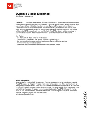
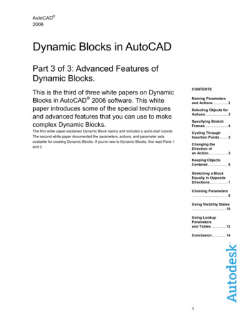
20Chapter 2 Leveraging a Dynamic EnvironmentEach of the objects listed previously can be controlled by styles. For example,surface styles can be used to show a surface in many forms, including contourlines, a 3-D grid, a series of arrows pointing downhill, shading representing different elevation ranges, and more (see Figure 2.1). In addition to changing theoverall appearance of an object, styles can control specific details that differslightly between similar configurations. For example, in one case there may besurface contours that need to be shown on an existing layer, whereas in anothercase the same contours are shown on a proposed layer (see Figure 2.2). Theconfiguration is the same (contours), but the way that configuration is displayed(which layer) is different between two different styles. F i g u re 2 . 1 The same surface is shown in four different configurations using four differentstyles (from left to right): contours, elevation banding, TIN lines and contours, and slope arrows.Copyright 2015. John Wiley & Sons, Incorporated. All rights reserved.The acronym TIN will becovered in Chapter 4.F i g u re 2 . 2 The contours on the left are displayed using proposed layers that are typicallydarker and more prominent. The contours on the right are displayed using existing layers that aretypically lighter, so they appear more as background information.Chappell, Eric. AutoCAD Civil 3D 2016 Essentials, John Wiley & Sons, Incorporated, 2015. ProQuest Ebook etail.action?docID 2052358.Created from osu on 2017-07-11 08:09:39.
Connecting Objects and StylesExercise 2.1: Apply Styles to ObjectsIn this exercise, you will use styles to change the appearance and behavior ofCivil 3D objects.1. Open the drawing named Objects and Styles.dwg located in theChapter 02 class data folder.The plan view of the surface in the left viewport should appearsimilar to the first image shown in Figure 2.1.2. Click one of the contour lines in the drawing to select the surfaceobject.3. If the Properties palette is not visible, click Properties on theHome tab of the ribbon.4. In the Properties window, change the Style property to ElevationBanding (2D).The surface will display as colored bands, representing differentranges of elevations, similar to the second image in Figure 2.1.Copyright 2015. John Wiley & Sons, Incorporated. All rights reserved.5. Change the Style property to Contours & Triangles.The surface should now appear similar to the third image inFigure 2.1. The triangles are the fundamental framework of the surface and give it the shape that it has.6. Change the Style property to Contours 1' and 5' (Design) (0.5 m and2.5 m (Design)).The surface should now resemble the left image in Figure 2.2.7. Change the Style property to Contours 1' and 5' (Background) (0.5 mand 2.5 m (Background)).Chappell, Eric. AutoCAD Civil 3D 2016 Essentials, John Wiley & Sons, Incorporated, 2015. ProQuest Ebook etail.action?docID 2052358.Created from osu on 2017-07-11 08:09:39.21 If you haven’t alreadydone so, downloadand install the files forChapter 2 according tothe instructions in thisbook’s Introduction. Notice that when youclick a contour, theentire surface objectis selected and allthe contours appearhighlighted.This is the style thatwas assigned to thesurface when you firstopened the drawing.Note that both of thelast two styles displayed contours but ondifferent layers. Someof the contours changeto the new color as aresult of this change.
22Chapter 2 Leveraging a Dynamic EnvironmentWhat Are Contours?Contours are lines that are used to represent topography or changes in elevationacross the ground. Most people experience contours in things like trail maps thatcover a large area (square miles or square kilometers) in comparison to what wetypically see in Civil 3D. By definition, contours are lines that connect points ofequal elevation. If you took a giant horizontal blade and passed it through theground at equal elevation intervals, you would get contour lines. In flat areas,the lines would be far apart, and in steep areas, the lines would be close together.With practice, you can look at a contour map and visualize the 3D shape of theland that the map represents.Copyright 2015. John Wiley & Sons, Incorporated. All rights reserved.The Tin Surface:Existing Ground tabis an example of aspecial ribbon tab thatis displayed becauseyou selected a surface. These are oftenreferred to as contextual ribbon tabs, as youmay remember fromthe previous chapter. Steep AreaFlat Area8. With the surface still selected, click the Tin Surface: Existing Groundribbon tab and then click Surface Properties Edit Surface Style.9. Click the Display tab, and then click the color column next to MajorContour. Some of the contourschange to the newcolor as a result of thischange.10. Choose a noticeable color, and click OK. Click OK again to return tothe drawing.11. Save and close the drawing.You can view the results of successfully completing this exercise by openingObjects and Styles - Complete.dwg.As you worked through the previous exercise, did you notice that no extrasteps were required to update or redraw the surface when a new style wasassigned or the style was edited? The effect was immediate—as soon as youmodified the assigned style or assigned a different style, the appearance of thesurface changed. This is because of a dynamic relationship between the objectand its style, a relationship that is honored throughout the software.Chappell, Eric. AutoCAD Civil 3D 2016 Essentials, John Wiley & Sons, Incorporated, 2015. ProQuest Ebook etail.action?docID 2052358.Created from osu on 2017-07-11 08:09:39.
Connecting Labels and Label Styles23Editing a Style vs. Assigning a Different StyleIn steps 4 through 7 of the previous exercise, you changed the appearance of thesurface by assigning a different style to it. This is the way to do it 99 percent ofthe time. In steps 8 through 10, you edited the style that was already assignedto the surface. Editing styles is typically the responsibility of a CAD manager. Infact, in many companies, end users are not permitted to modify or create styles.However, it is still important to understand that when a style is modified, anyobject using that style will change its appearance or behavior to honor the newversion of the style.Copyright 2015. John Wiley & Sons, Incorporated. All rights reserved.Connecting Labels and Label StylesLabels are an important part of any design because they provide specific information about the design that is often necessary for it to be properly constructed.Civil 3D enables you to create many different types of labels that associate themselves with the different types of Civil 3D objects. Labels are Civil 3D objectstoo, and just like the objects listed in the previous section, their appearance andbehavior are controlled by styles. Also, just as with the relationship betweenobjects and their styles, labels react when a different style is assigned or theassigned style is modified.Here are some label types that correspond to the Civil 3D objects listed in theprevious section:Surface Spot Elevation Label This type of label is typically used to displaythe elevation of a key point in the design, such as a low point that water willdrain toward or a high point that water will drain away from.Alignment Station Offset Label This type of label is used to express thelocation of a feature in reference to a linear object. For example, you can expressthe location of a manhole by saying that it is a certain distance along the lengthof the road (station) and a certain distance to the left or right of it (offset).Chappell, Eric. AutoCAD Civil 3D 2016 Essentials, John Wiley & Sons, Incorporated, 2015. ProQuest Ebook etail.action?docID 2052358.Created from osu on 2017-07-11 08:09:39.CertificationObjective
24Chapter 2 Leveraging a Dynamic EnvironmentProfile Grade Break Label This type of label is used to show the location andelevation of a slope change along a profile. For example, if the profile slopes upwardand then changes to a downward direction, the highest point where the changeoccurs is considered a grade break and is a common location to place a label.Copyright 2015. John Wiley & Sons, Incorporated. All rights reserved.Station and OffsetLong linear designs such as roads and pipelines often use station and offsetnotation to express locations. Stations themselves are usually expressed in aspecial notation that has a plus sign in it.For example, if you’re working in imperial units, a station of 2 00 refers to alocation that is 200 feet “down the road” (assuming the road begins at station0 00). To get to station 2 00, offset 12', you would travel down the road exactly200 feet, turn right exactly 90 degrees, and travel exactly 12 feet.If you’re working in metric units, a common format is to use three digits after theplus sign. In this case, a station of 0 200 refers to a location 200 meters downthe road. To get to station 0 200, offset 4 m, you would travel 200 meters downthe road, turn right exactly 90 degrees, and travel exactly 4 meters.Chappell, Eric. AutoCAD Civil 3D 2016 Essentials, John Wiley & Sons, Incorporated, 2015. ProQuest Ebook etail.action?docID 2052358.Created from osu on 2017-07-11 08:09:39.
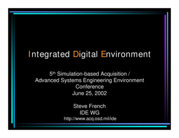
Connecting Labels and Label Styles25Parcel Segment Label This type of label is typically used to express geometric information about a line or curve that forms part of a legal boundary. Forexample, it is common to label the bearing and distance of a straight line segment along a property boundary.Exercise 2.2: Apply Label Styles to Labels In this exercise, you will use label styles to change the appearance and behaviorof labels.If you haven’t alreadydone so, downloadand install the files forChapter 2 according tothe instructions in thisbook’s Introduction.1. Open the drawing named Labels and Styles.dwg located in theChapter 02 class data folder.Copyright 2015. John Wiley & Sons, Incorporated. All rights reserved.2. In the top-right viewport, click the label. If the Properties palette isnot visible, click Properties on the Home tab of the ribbon.3. Change the value for Station Offset Label Style to Station And Offset,as shown in Figure 2.3. Notice how the content of the label changes.F i g u re 2 . 3 Assigning the Station And Offset label style to the labelChappell, Eric. AutoCAD Civil 3D 2016 Essentials, John Wiley & Sons, Incorporated, 2015. ProQuest Ebook etail.action?docID 2052358.Created from osu on 2017-07-11 08:09:39.
26Chapter 2 Leveraging a Dynamic Environment4. Change the value for Station Offset Label Style to Station And Offset– Existing. This time, the content stays the same but the style of thetext changes. This is anotherexample of acontextual ribbon tab.5. With the label still selected, click Label Properties Edit Label Styleon the Labels – Alignment Station Offset Label contextual ribbon tab.6. In the Station Offset Label Style dialog box, click Edit CurrentSelection, as shown in Figure 2.4.Copyright 2015. John Wiley & Sons, Incorporated. All rights reserved.F i g u re 2 . 4 Clicking the Edit Current Selection command for the selectedlabel style7. In the Label Style Composer dialog box, click the Dragged Statetab. Change the Visibility value for the leader to False, as shown inFigure 2.5.The label is updated toreflect the change tothe style and no longerdisplays a leader. F i g u re 2 . 5 Changing the visibility of the leader by modifying a label style8. Click OK twice to dismiss all dialog boxes and return to the drawing.9. Save and close the drawing.You can view the results of successfully completing this exercise by openingLabels and Styles - Complete.dwg.Chappell, Eric. AutoCAD Civil 3D 2016 Essentials, John Wiley & Sons, Incorporated, 2015. ProQuest Ebook etail.action?docID 2052358.Created from osu on 2017-07-11 08:09:39.
Connecting Objects to Objects27Styles and Company StandardsCivil 3D styles can make it easier for end users to meet company standards and canmake graphical output more consistent. With a good set of styles that integratecompany standards, all that an end user has to worry about is choosing the rightstyle from a manageable list of choices. Conversely, if end users have to createtheir own styles, labels, and/or other graphical components, their drawings willmost likely vary and may not comply with those standards.Copyright 2015. John Wiley & Sons, Incorporated. All rights reserved.Connecting Objects to ObjectsThe most important type of relationship that you’ll see in this chapter is the onebetween objects. A typical land development project is a collection of dozens ofmini-designs that often tie in to one another. For example, a road is designed byfirst drawing the 2D path of its centerline, then the proposed changes in elevation along that centerline, and finally the lanes, curbs, and sidewalks extendingoutward from that centerline. To provide drainage during a rainstorm, ditchesmust be installed along the sides of the road. The location and depth of theseditches can be traced back through the design process the entire way to thelayout of the road centerline. If the layout of the centerline needs to change forsome reason, that change must propagate downstream through the design process, ultimately changing the location and depth of one or more ditches.Before Civil 3D, the many implications of such a change had to be addressedmanually. An engineer or designer would have to inspect the road elevations,curbs, sidewalks, and ditches and manually address any changes requiredbecause of a change “upstream” in the design. With Civil 3D, you can build relationships between design objects and cause these changes to take place automatically, saving time and money and reducing opportunity for human error.Exercise 2.3: Explore Object RelationshipsIn this exercise, you will study how object relationships are leveraged to makedesign changes in a drawing.1. Open Object Relationships.dwg located in the Chapter 02 classdata folder.Chappell, Eric. AutoCAD Civil 3D 2016 Essentials, John Wiley & Sons, Incorporated, 2015. ProQuest Ebook etail.action?docID 2052358.Created from osu on 2017-07-11 08:09:39. If you haven’t alreadydone so, downloadand install the files forChapter 2 according tothe instructions in thisbook’s Introduction.
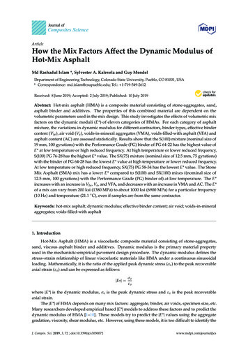
28Chapter 2 Leveraging a Dynamic Environment2. Press the F3 key, and observe the command line. If it reports OsnapOn , then press F3 again. If it reports Osnap Off , this is the correctcondition for this exercise, and you can move on to the next step. Osnap Off prevents your cursor fromlocking on to objects inthe drawing that arenear it. Copyright 2015. John Wiley & Sons, Incorporated. All rights reserved.Be sure that your command line is dockedat the bottom of yourscreen and that thebackground color isset to white beforeproceeding withthese steps.3. Click the top-right viewport, which shows a profile of the roaddesign. The black lines represent the elevations along the centerlineof the new road. The blue lines represent storm drains and pipesconnecting them.4. Click the black line representing the road profile. Zoom in untilyou can clearly see the triangular grip located at the intersection oftwo lines.5. Click the triangular grip, and drag it upward to a location just belowthe top edge of the profile view grid, as shown in Figure 2.6.Notice that the 3-D view (bottom-right) of the road automaticallyupdates, including the height of the Inlet 2 drain. In the profile view(top-right), the top of the drain is elevated to match the road.F i g u re 2 . 6 Grip-editing the profile6. Save and close the drawing.You can view the results of successfully completing this exercise by openingObject Relationships - Complete.dwg.This simple exercise illustrates the power of relationships between objects.The ease with which you just updated the design may cause you to take theunderlying processes for granted; however, there is a lot happening behind theChappell, Eric. AutoCAD Civil 3D 2016 Essentials, John Wiley & Sons, Incorporated, 2015. ProQuest Ebook etail.action?docID 2052358.Created from osu on 2017-07-11 08:09:39.
Connecting Objects to Labelsscenes. The following is a general account of the events that took place whenyou changed the location of the triangular grip: The slopes of the lines leading into that triangular grip were changedto match the new location of the grip. The parabolic curve geometry at the location of the grip was updatedautomatically. The corridor object, which represents a 3-D model of the road,was automatically rebuilt and updated to match the new profilegeometry. A surface representing the pavement, concrete, and earthen embank-ment elevations of the corridor was automatically rebuilt. The storm drain updated its top elevation to match the surface in theprevious step. The 3-D representation of the storm drain was automatically updated(bottom-right view). The profile view representation of the storm drain was automaticallyCopyright 2015. John Wiley & Sons, Incorporated. All rights reserved.updated (top-right view).A simple grip edit triggered a chain of events that might have taken an houror more to update manually. In addition to all this, other changes took placethat did not affect the design of the storm drain. This is the power of the Civil3D dynamic environment. You should know, however, that the existence ofthese relationships is not necessarily automatic. They have to be considered andat times consciously built in to the design by the Civil 3D user.Connecting Objects to LabelsThere is also an important relationship between objects and labels. Labeling isone of the most time-consuming aspects of preparing a set of construction documents. Although it is a very important part of the process, it really has nothingto do with the design. Usually, labels are placed when the design is already complete, as a means of communicating the necessary information for constructingthe design in the field. The big advantage of the dynamic relationship betweenobjects and labels is that it enables the user to create a single label that is validfor the life of the object. As the object changes, the label changes with it—sothe label is always up to date and never has to be edited manually.Chappell, Eric. AutoCAD Civil 3D 2016 Essentials, John Wiley & Sons, Incorporated, 2015. ProQuest Ebook etail.action?docID 2052358.Created from osu on 2017-07-11 08:09:39.29
30Chapter 2 Leveraging a Dynamic Environment If you haven’t alreadydone so, downloadand install the files forChapter 2 according tothe instructions in thisbook’s Introduction.Exercise 2.4: Explore the Relationship BetweenObjects and LabelsIn this exercise, you will study how dynamic labels respond when changes aremade to the objects they annotate.1. Open Objects and Labels.dwg located in the Chapter 02 class datafolder. Notice the elevation label, which currently reads 190.02 (57.92).2. Click one of the dark gray contour lines. On the ribbon, click EditSurface Paste Surface. This step is like usinga bulldozer to cut theroad into the hillside,causing the elevationto drop about 3 feet(1 meter).3. Select Main Road A FG, and click OK. Press Esc to clear the selection.In the top-right viewport, notice how the label updates and nowreads 187.33 (57.07).4. In the top-right viewport, pan southward and note the station valueof 10 95.68 (0 333.96) and the offset value of 68.49L (20.88m L) inthe label to the south of the spot elevation.Copyright 2015. John Wiley & Sons, Incorporated. All rights reserved.5. Click the road centerline to select it and display its grips. Then clickthe triangular grip and drag it west to a point near the west edge ofthe road, as shown in Figure 2.7.F i g u re 2 . 7 Grip-editing the alignmentAfter a pause while Civil 3D rebuilds several aspects of the design,the label updates once more. Because the road is no longer influencing the elevation of this spot, the label reverts to its original value of190.02 (57.92). The station offset label now displays updated valuesfor station and offset.6. Save and close the drawing.Chappell, Eric. AutoCAD Civil 3D 2016 Essentials, John Wiley & Sons, Incorporated, 2015. ProQuest Ebook etail.action?docID 2052358.Created from osu on 2017-07-11 08:09:39.
Appreciating the Richness of the 3-D ModelYou can view the results of successfully completing this exercise by openingObjects and Labels - Complete.dwg.Copyright 2015. John Wiley & Sons, Incorporated. All rights reserved.Appreciating the Richness of the 3-D ModelEven though what you have done to this point may seem a bit foreign at themoment, at some point you will realize that all you’re doing with Civil 3D is creating instructions for how to build something. If you’ve ever assembled a pieceof furniture or a bicycle that you bought at a store, you can relate to this concept. The primary purpose of Civil 3D is to help you prepare the instructions forhow to build a land development project.Thirty years ago, the method used to prepare land development plans wasrelatively the same as it had been for hundreds of years: plans were drawn onpaper, providing only a two-dimensional depiction of what was to be built. Theinformation that existed for the design was limited to what could be displayedon paper. Then, with the advent of computers, something magical started tohappen. Virtual versions of design components could be modeled electronically.They could be represented in all three dimensions and even have additionalinformation attached to them. Now, instead of using an ink line on paper torepresent a pipe, you could do it with a 3-D cylinder that also stored the pipe’smaterial, structural characteristics, and flow characteristics. This “smart”object could be ported to hydraulic design software for further analysis in conjunction with local rainfall data to determine whether it was large enough tohandle a storm with a specific likelihood of occurring within the life span of thepipe. And so on, and so on.Thus, in 30 years we have progressed from ink on paper to 3-D intelligentobjects. The step from drawing with a pen to drawing with a mouse came earlyin that evolution—not 3D or intelligent, but lines on a screen that could beprinted. Civil 3D contains all the basic tools to represent designs in this manner,and unfortunately, many users create only basic 2-D drawings even though theyhave access to the dynamic 3-D environment that you’ve seen in this chapter.My sincere hope is that you will not be this type of end user but instead willsqueeze every dynamic relationship possible into the models you build with Civil3D. You may not realize the full potential of the dynamic relationships you builduntil you have the opportunity to use them, but you can bet that they will paydividends on every single project. The following are examples where it is essential to have a dynamic 3-D model.Chappell, Eric. AutoCAD Civil 3D 2016 Essentials, John Wiley & Sons, Incorporated, 2015. ProQuest Ebook etail.action?docID 2052358.Created from osu on 2017-07-11 08:09:39.31
32Chapter 2 Leveraging a Dynamic EnvironmentBuilding Information ModelingBuilding information modeling (BIM) has been a hot topic in the design, construction, and facilities management fields for quite some time now. Althoughsome would argue that Civil 3D has little to do with the B (building), it definitelyhas the I (information) and the M (modeling) aspects. Many civil engineeringprojects are incidental to building construction and therefore present an opportunity for Civil 3D models to be integrated with BIM. No model, no BIM.GPS-Guided Machine ControlImagine being able to download the instructions to assemble your bike and thenupload them to your own personal robot, which would assemble the bike foryou. That might sound like science fiction, but something similar is commonpractice in the land development industry. Models built with Civil 3D are beinguploaded to GPS-guided earthmoving machines. These giant “robots” synchronize GPS-based locations of themselves and their digging implements with thedimensions of the Civil 3D model until the real dirt and rock are a match to themodel. Without a model, there is no GPS-guided machine control.Copyright 2015. John Wiley & Sons, Incorporated. All rights reserved.Construction SimulationIf you think about it, one thing that Civil 3D enables you to do is to simulatethe project before having the contractor attempt to bui
the lines would be far apart, and in steep areas, the lines would be close together. With practice, you can look at a contour map and visualize the 3D shape of the land that the map represents. Steep Area Flat Area 8. With the surfa