Transcription
International Journal of Engineering Research & Technology (IJERT)ISSN: 2278-0181Vol. 4 Issue 04, April-2015Design of Formula One Racing CarTriya Nanalal VadgamaMr. Arpit Patel,StudentDepartment of Aeronautical EngineeringSardar Vallabhbhai Patel Institute of Technology, VasadGujarat Technological University, Ahmedabad, IndiaAssistant ProfessorDepartment of Aeronautical EngineeringSardar Vallabhbhai Patel Institute of Technology, VasadGujarat Technological University, Ahmedabad, IndiaDr. Dipali Thakkar,Head & ProfessorDepartment of Aeronautical EngineeringSardar Vallabhbhai Patel Institute of Technology, VasadGujarat Technological University, Ahmedabad, IndiaAbstract- A modern Formula One (F1) Racing Car has almost asmuch in common with an aircraft as it does with an ordinaryroad car. Aerodynamics has become a key to success in the sportand teams spend millions of dollars on research anddevelopment in the field each year for improving performance.The aerodynamic designer has two primary concerns :i.the creation of downforce, to help push the car’s tyresonto the track and improve cornering forces,ii.to minimise the drag that occurs due to turbulence andacts to slow down the car.In this project, a Formula One race car will be designed usingthe CAD software CATIA V5R20. All the dimensions are basedon the standards laid down by the FIA (FédérationInternationale de l'Automobile). The car design will beenhanced to streamline the flow over the car. Various parts thatwill be designed include the wheels, front and rear airfoils, frontand rear wings, car body chassis, among other subassemblies. Adriver will also be placed in a typical driving position inside thecar.Keywords- Formula One race car, Airfoil, Aerodynamics, Bodychassis, driver.I. INTRODUCTIONOn the surface, automobile racing appears simply as apopular sport. But in reality, racing serves as a provingground for new technology and a battlefield for the giants ofautomobile industry. Although human factors are frequentlypublicized as the reason behind the success or failure of oneracing team or another, engine power, tire adhesion, chassisdesign, and recently, aerodynamics probably play a veryimportant role in winning this technology race.One of the most important aspects of Formula One (F1)car design is aerodynamics. Creating down force, to hold thecar to the ground to improve cornering; and minimizing drag,which slows the car down are two primary concerns whendesigning the car. Modern F1 teams use expensive windtunnels and computational fluid dynamics systems to analyzethe effectiveness of an aerodynamic design for a car. In theseanalyses, every surface of the car, including the driver'shelmet must be considered. Even an advertising sticker canIJERTV4IS040962affect the airflow, and placing a badge on a crucial elementcould produce a two-to-three percent difference in airpressure. Disrupted air flow can cause turbulence, which willproduce drag to slow the car. F1 cars often have small'winglets' before the rear wing, which 'clean up' complex airflow in order to maximize down force. The scope of thisproject includes :i.Designing of F1 three-dimensional CAD modelusing CATIA V5 R21 software.The CAD model will be rectified before simulating it. Thecorrections are necessary to ensure an accurate representationof the aerodynamic geometry of the car. These will be donein three steps:i. Assembling missing components,ii. Redesigning lost parts or parts that were missing,iii. Resizing components with accurate dimensions andfeatures.The internal geometry, such as the engine and transaxle, willnot be included as the primary focus of this project is externalflow. As such, the internal parts will be removed from theCAD model.A. Formula One Background HistoryThe Formula One (F1) World Championship is thehighest class of single-seat auto racing in the world. It issanctioned by the FIA (Fédération Internationale del'Automobile). Formula One cars can reach speeds upto 330km/h. The FIA controls and regulates all the sizes anddimensions of Formula One car. These strict regulations ledto similarly-dimensioned cars. A typical car will be 463cmlong, 180cm wide and 95cm high.Flexible bodywork, with the exception of the rear-wing, isstrictly prohibited. Moreover, any device, system orprocedure which uses driver movement to alter theaerodynamic characteristics of the car’s bodywork is strictlyprohibited. Sections of bodywork, such as front wing end-www.ijert.org (This work is licensed under a Creative Commons Attribution 4.0 International License.)702
International Journal of Engineering Research & Technology (IJERT)ISSN: 2278-0181Vol. 4 Issue 04, April-2015plates, are required to be sufficiently thick to prevent damageto tyres of other cars.B. Ferrari F10 BackgroundThe Ferrari F10 is built by Scuderia Ferrari Marlbolo.1) Specifications :Chassis: Carbon fiber and honeycomb composite structureGearbox: Ferrari 7-speed ( reverse) longitudinal gearboxDifferential & gearbox: Limited slip differential,Semi-automatic sequential electronically controlled gearboxBrakes: Ventilated carbon fibre disc brakesSuspension: Independent suspension, push rod activatedtorsion springs, front and rear2) Engine :Engine: type 056Cylinders: V8 90 Cylinder Block: Cast AluminiumNumber of Valves: 32,Pneumatic DistributionTotal Displacement: 2398 Cm³Piston Bore: 98 MmWeight: 95 KgInjection: Magneti MarelliDigital Electronic InjectionIginition: Magneti MarelliStatic Electronic IgnitionFuel: Shell V-PowerLubricant: Shell Helix Ultra3) Dimensions :Wheelbase: 3050mmFront Track: 1470mmRear Track: 1405mmOverall Length: 4545mmOverall Height: 959mmOverall Width: 1796mmOverall Weight: 600kg,including driver and cameraWheels, Front And Rear: 13"Fig. 3 Top View of F10C. Aerodynamics BackgroundAerodynamics is a branch of dynamics concernedwith studying the motion of air, particularly when it interactswith a moving object. Aerodynamics is a subfield of fluiddynamics and gas dynamics, with much theory sharedbetween them. It is often used synonymously with gasdynamics, with the difference being that gas dynamicsapplies to all gases.Understanding the motion of air (often called a flowfield) around an object enables the calculation of forces andmoments acting on the object. Typical properties calculatedfor a flow field include velocity, pressure, density andtemperature as a function of position and time. By defining acontrol volume around the flow field, equations for theconservation of mass, momentum, and energy can be definedand used to solve for the properties.Aerodynamics has become key to success in theFormula One sport and spends of millions of dollars onresearch and development in the field each year. Theaerodynamic design has two primary concerns.i.The creation of downforce to help push thecar’s tires onto the track and improve thecornering force.ii.To minimizing the drag that caused byturbulence and act to slow the car down.The drag over a body can be minimized bystreamlining it (smooth exterior surface). As a result, therewill be potential improvements in fuel economy. [Fig.4 & 5]Fig. 1 Front View of F10Fig. 4 Flow Over A Streamlined Bodyof Race Care Aerodynamics – By Joseph Katz)(CourtesyFig. 2 Side View of F10IJERTV4IS040962www.ijert.org (This work is licensed under a Creative Commons Attribution 4.0 International License.)703
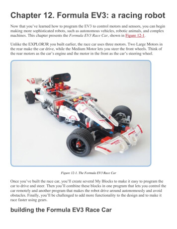
International Journal of Engineering Research & Technology (IJERT)ISSN: 2278-0181Vol. 4 Issue 04, April-2015(CourtesyFig. 8 Schematic description of the flow field over an open-wheel F1 racecar. (Courtesy of Race Car Aerodynamics – By Joseph Katz)Fig. 5 Aerodynamic Forcesof Race Care Aerodynamics – By Joseph Katz)D. Selection of AirfoilNACA 4-series airfoils are the most widely used airfoils forFormula One race cars. The NACA four-digit wing sectionsdefine the profile by:i. First digit - maximum camber as percentage of the chord.ii. Second digit - the distance of maximum camber from theairfoil leading edge in tens of percentage of the chord.iii. Last two digits - maximum thickness of the airfoil as apercentage of the chord.Fig. 6 Schematic description of the “Ground Effect” that increases theaerodynamic lift of the wings when placed near the ground.(Courtesy of Race Care Aerodynamics – By Joseph Katz)1) Front Wing Airfoil – NACA 4412The Front Wing of a Formula One car creates about 25% ofthe total car’s downforce. This is one of the most widely usedspoiler airfoil, but needs to be enhanced as per speed. Such athicker airfoil is used to obtain the desired higher downforcefrom the front end of the car, at a given speed.Fig. 9 NACA 4412Fig. 7 Schematic description of the effect of rear wing on the streamlinesnearby a generic body. (Courtesy of Race Care Aerodynamics – By JosephKatz)An inverted airfoil to generate a negative lift force –Downforce. This leads to major improvements in race carperformance, especially on tracks with numerous high-speed,unbanked turns. Aerodynamic downforce increases the tires’cornering ability by increasing loads on the tires withoutincreasing the vehicle’s weight. The result is increasedcornering ability, with no weight penalty, which gives areduction in lap times.IJERTV4IS0409622) Rear Wing Airfoil – NACA 2408Due to location of engine at the rear end of the car, moredownforce is generated. Hence, to compensate forminimization of downforce from rear end, a thinner airfoil isused. Thinner airfoil also helps to maintain the continuity ofthe flow without flow separation. Thus, NACA 2408 isemployed at the rear end.Fig. 10 NACA 2408www.ijert.org (This work is licensed under a Creative Commons Attribution 4.0 International License.)704
International Journal of Engineering Research & Technology (IJERT)ISSN: 2278-0181Vol. 4 Issue 04, April-2015II. CAD (COMPUTER-AIDED DESIGN) MODELDEVELOPMENT USING CATIA V5R20A. Wheel :Fig. 14 Assembly – Zero Angle of AttackFig. 11 Isometric View of WheelFig. 15 Assembly – Zero Angle of Attack – Different ViewsFig. 12 Different Views of WheelB. Front Wing :Fig. 16 Assembly – Negative (-150) Angle of AttackFig. 13 Airfoil – NACA 4412Fig. 17 Assembly – Negative (-150) Angle of Attack – Different ViewsIJERTV4IS040962www.ijert.org (This work is licensed under a Creative Commons Attribution 4.0 International License.)705
International Journal of Engineering Research & Technology (IJERT)ISSN: 2278-0181Vol. 4 Issue 04, April-2015C. Rear Wing :Fig. 18 Airfoil – NACA 2408Fig. 21 Assembly – Negative (-150) Angle of AttackFig. 19 Assembly – Zero Angle of AttackFig. 22 Assembly – Negative (-150) Angle of Attack – Different ViewsFig. 20 Assembly – Zero Angle of Attack – Different ViewsIJERTV4IS040962www.ijert.org (This work is licensed under a Creative Commons Attribution 4.0 International License.)706
International Journal of Engineering Research & Technology (IJERT)ISSN: 2278-0181Vol. 4 Issue 04, April-2015D. Car Body Chassis :Fig. 23 Isometric viewFig. 24 Different ViewsIJERTV4IS040962www.ijert.org (This work is licensed under a Creative Commons Attribution 4.0 International License.)707
International Journal of Engineering Research & Technology (IJERT)ISSN: 2278-0181Vol. 4 Issue 04, April-2015E. Human Driver :TABLE 1. HUMAN POSTURE ANALYSISSegmentsAngleDegree OfFreedomArm (Left & Right)600FlexionForearm (Left & Right)200FlexionFull Spine (Lumbar Thoracic) 56.5680FlexionFig. 25 Human Driver built using HumanBuilder of Ergonomics Design & Analysismodule of CATIA (Inset view : Helmet)IJERTV4IS040962HeadLeg (Left & Right)Line of SightLumbarThigh (Left & Right)ThoracicHand (Left & Right)Index 1 (Left & Right)Index 3 (Left & Right)Middle Finger 1 (Left & ionFlexionMiddle Finger 3 (Left & Right)800FlexionAnnular 1 (Left & Right)Annular 3 (Left & Right)Auricular 1 (Left & Right)100800100FlexionFlexionFlexionAuricular 3 (Left & Right)800Flexionwww.ijert.org (This work is licensed under a Creative Commons Attribution 4.0 International License.)708
International Journal of Engineering Research & Technology (IJERT)ISSN: 2278-0181Vol. 4 Issue 04, April-2015F. Car :Fig. 26 Isometric ViewIJERTV4IS040962www.ijert.org (This work is licensed under a Creative Commons Attribution 4.0 International License.)709
International Journal of Engineering Research & Technology (IJERT)ISSN: 2278-0181Vol. 4 Issue 04, April-2015OVERALL LENGTH 4545mmOVERALL WIDTH 1800.06 mmTOTAL HEIGHT 959mmREAR TRACK 1405mmFRONT TRACK 1470mmWHEEL WIDTH 330.2mmWHEELBASE 3069.8 mmFig. 27 Front viewFig. 28 Back viewIJERTV4IS040962www.ijert.org (This work is licensed under a Creative Commons Attribution 4.0 International License.)710
International Journal of Engineering Research & Technology (IJERT)ISSN: 2278-0181Vol. 4 Issue 04, April-2015Fig. 29 Left-hand side viewFig. 30 Right-hand side viewFig. 32 Bottom viewFig. 31 Top viewIJERTV4IS040962www.ijert.org (This work is licensed under a Creative Commons Attribution 4.0 International License.)711
International Journal of Engineering Research & Technology (IJERT)ISSN: 2278-0181Vol. 4 Issue 04, April-2015I sincerely thank all other faculty members of theAeronautical Department for helping me in all possible waysfor the betterment of my project.III. FUTURE PLANS Computational Fluid Flow and Structural Analysis ofFront wing airfoil NACA 4412.Computational Fluid Flow and Structural Analysis ofRear wing airfoil NACA 2408.Computational Fluid Flow and Structural Analysis ofFront Wing Assembly.Computational Fluid Flow and Structural Analysis ofRear Wing Assembly.Computational Fluid Flow and Structural Analysis ofthe entire car model.Last, but certainly not the least, I am very thankful to myfamily and friends who have been giving me unconditionalsupport throughout the entire period of my project, becausewithout them, none of this would have been possible.REFERENCES[1][2][3][4][5][6][Validations will be based on Zero AOA results]ACKNOWLEDGEMENTIt is always a pleasure to remind the fine people whohelped me throughout my project.[7][8]I am extremely thankful to Dr. Dipali Thakkar for givingme an opportunity to undertake this project. I would like togive a special thanks and express my deep sense of gratitudeto Mr. Arpit Patel for his assistance, expert guidance, andsuggestions throughout this project work. Without the help oftheir knowledge and expertise in every facet of the study,from helping to find the relevant data and in analyzing theresults, this project would not have been completed.IJERTV4IS040962A rear spoiler with adjustable aerodynamic profiles for a highperformance road vehicle (WIPO; Patent No.: EP2631160; ApplicationNo.: 13156647; Inventor: de Luca Marco; Applicant: Ferrari SPA)Aerodynamics – by L.J. ClancyComputational Fluid Dynamics – by J.D. AndersonFormula One Technical Regulations – FIA StandardsFundamentals of Aerodynamics – by J.D. AndersonNumerical Investigation of Flow Transition for NACA-4412 airfoilusing Computational Fluid Dynamics (ISSN: 2319-8753; InternationalJournal of Innovative Research in Science, Engineering andTechnology - Vol. 2, Issue 7, July 2013)Race Car Aerodynamics – by Joseph KatzStudy of Front-Body of Formula One Car for Aerodynamics using CFD(ISSN: 2319-4847; International Journal of Application or Innovationin Engineering & Management (IJAIEM) - Volume 3, Issue 3, March2014)www.ijert.org (This work is licensed under a Creative Commons Attribution 4.0 International License.)712
car design is aerodynamics. Creating down force, to hold the car to the ground to improve cornering; and minimizing drag, which slows the car down are two primary concerns when designing the car. Modern F1 teams use expensive wind tunnels and computational fluid dynamics systems to analyze the effective