Transcription
White Paper3DS.COM Dassault SystèmesSystèmes3DS.COM DassaultCATIA V5 AdministrationCustomizing StandardsVersion 1.0 – 3/1/2014Written by: Bill DukeValidated by: NAEdited by: Anne Marie Miller
White PaperExecutive SummaryIt is possible to operate CATIA V5 with the default Standards delivered with the code,but many companies customize these Standards to best meet their needs and theneeds of their suppliers. Supply Chain companies may also have to manage amultitude of Standards from other companies along with their own. This sessiondiscusses the steps required to customize the different Standards, and how to sharethe customized Standards across multiple environments and workstations. Thissession is intended for the beginner to intermediate System Administrator, in order tocreate a working knowledge of the setup of custom Standards.The administration of your CAD/CAM systems is an important part of the overallability to keep your workstations effective in your business. Because manycompanies create their own custom Standards to best meet their needs and the needsof their suppliers, a clear understanding of how to customize the Standards isrequired. This paper focuses on the information that is necessary for maintainingCATIA’s Standards. Having this knowledge allows the Administrator to easily set upspecific company Standards, and to manage Standards received from othercompanies.This document is intended for Systems Administrators, Application Engineers, andTechnical Support Members who require an understanding of V5 ClientAdministration. The information was generated from the experiences gained throughmany years of experience of administering CATIA V5 and on many installs of variouslevels of the V5 code. Although this paper is written based on a V5R21, it is applicableto all levels of V5.23DS.COM Dassault SystèmesIntroduction
White PaperContentsWhat are the CATIA V5 Standards?. 41.1.Types of Standards . 41.2.Categories of Standards . 51.2.1.General Parameters. 51.2.2.Drafting Parameters . 61.2.3.DFX/DWG Interface Parameters . 61.2.4.Generative Parameters . 62.Customizing the CATIA V5 Standards . 92.1.Define Environment Variables . 92.2.Create the Required Directories . 102.3.Access of Standard Definitions in CATIA V5 admin mode . 112.4.Select a default Standard – Modify and Save . 133.Managing the CATIA V5 Standards . 153.1.Tips for Defining Drafting Standards Directories . 153.2.Tips for Controlling Multiple Customized Drafting Standards . 153.3.Editing the Standard XML files using a Text Editor . 163.4.Updating Standards from previous CATIA Levels . 173.5.“Tools – Options” for controlling Standards . 193.5.1.Drafting Standards Settings . 193.5.2.DXF/DWG Standards Settings . 204.Sharing of Customized CATIA V5 Standards . 205.Conclusion . 226.References . 227.Revision History . 228.Related Documentation. 229.Document History . 223DS.COM Dassault Systèmes1.
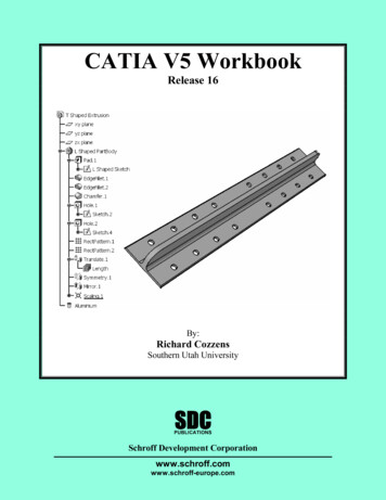
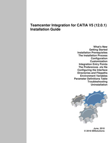
White Paper1. What are the CATIA V5 Standards?The CATIA V5 Standards define default values for the element properties within CATIA.Although CATIA can be use out of the box with the Standards defined by DassaultSystèmes, many companies do customize these Standards, to meet their needs and theneeds of their suppliers. Because of this, it is important to understand the CATIA V5Standards and how to manage them.1.1.Types of StandardsThere are two types of Standards available with CATIA V5. The first type is the DefaultStandards, which are provided by Dassault Systèmes. These files are stored in the locationdefined by the environment variable CATDefaultCollectionStandard. The default locationof the default Standards is set by Dassault Systèmes to be the“install folder”\resources\standard. Figure 1 shows an example for the default Windowsfolder for a Windows 64-bit installation:The second type of Standards available is the user Standards, which are also known as theCustomized Standards. These Standards are created and managed by the CATIA V5Administrator. They are stored in the location defined by the environment variableCATCollectionStandard. By default, a value for this environment variable is not defined, asshown in Figure 1.Figure 1 – V5R21 Environment Editor43DS.COM Dassault SystèmesC:\Program Files\Dassault Systemes\B21\win b64\resources\standard
White Paper1.2.Categories of StandardsThere are four different categories of Standards. Each of the Standards affects differentCATIA documents and workbenches. All of the CATIA V5 Standards are defined in XML(Extensible Markup Language) files, with specific names, and are stored in specific locationsin the Standards directory structure.The XML file names of the Standards cannot be modified or customized with the exceptionof the Drafting Standards. Only Drafting Standards can have customized XML file names. Allof the other Standards must keep use the names as defined by Dassault Systèmes.The following sections describe the four Standards categories that are used to defineCATIA’s attributes.1.2.1.General ParametersThe General Parameters Standards include the following four areas:These Standards define the general graphic attributes for Lines, Points, Planes, Surfaces,Solids and OpenBodies. They are defined in the file CATStdMechanicalDesign.xml. Thisfile by default is not provided in the “install folder”\resources\standard directory. To be able tomodify it, it must be copied from the “install folder”\startup\templates directory into the“install folder”\resources\standard directory.Attributes for Layers and FiltersThese Standards define attributes for Layers and Filters in CATParts and CATDrawings.For CATParts, the Standards are defined files CATStdLayersAndFilters.xml andCATStdTypeLayerAndFilter.xml.For CATDrawings, the Standards are defined in the files CATDftStdLayersAndFilters.xmland CATDftStdTypeLayerAndFilter.xml.These files are located in the directory “install folder”\resources\standardNote: Even though the xml files CATStdTypeLayerAndFilter.xml andCATDftStdTypeLayerAndFilter.xml are located in the directory“install folder”\resources\standard (as shown in Figure 2), they are not editable as theyare used only to define the layer and definition types used in theCATStdLayersAndFilters.xml and CATDftStdLayersAndFilters.xml files.Attributes for Line ThicknessThese Standards define Line Thickness attributes for CATDrawings. The Standards aredefined in the file CATStdLineThickness.xml, which is located in the directory“install folder”\resources\standard53DS.COM Dassault SystèmesDefault Graphic Attributes
White PaperAerospace SheetMetal Design ParametersThese Standards define the graphic properties and visibility characteristic curves used in theAerospace SheetMetal Design Workbench. The Standards are defined in the fileAerospaceSheetMetalDesign.xml,which is located in the directory“install folder”\resources\standard1.2.2.Drafting ParametersThese Standards define the attributes for drafting elements used in CATDrawings for theInteractive and Generative Drafting Workbenches.Dassault Systemes provides eleven Drafting Standard files. One for each of the fourInternational Drafting Standards, two Drafting Standards and five for use with otherworkbenches.The International Drafting Standards files provided with the CATIA V5 code are:ANSI.xml, ASME.xml, ISO.xml and JIS.xmlThe Drafting Standards based on the ISO 3098 standard defining text representation are:The remaining five Drafting Standards are specifically intended for the 2D Layout for 3DDesign, and the Functional Tolerancing and Annotation workbenches. They are based onthe Drafting Standards and are suffixed with 3D (for Drafting) or with 3D DS (forFunctional Tolerancing and Annotation). In these specific Standards, the colors, forexample, have been customized for optimized display. The five Standards are provided inthe files:ASME 3D.xml, ISO 3D.xml, ISO 3D DS.xml, JIS 3D.xml, and JIS 3D DS.xmlAll of the Drafting Standard files are located in the directory“install folder”/resources/standard/drafting1.2.3.DFX/DWG Interface ParametersThese Standards define the import mapping parameters of element properties for DXF/DWGfiles coming into CATIA V5.They are defined in the DXF.xml file. This file is located in the directory:“install folder”\resources\standard\dxf1.2.4.Generative ParametersThese Standards define the Generative View Styles in the Generative Drafting Workbench.They are defined in the file DefaultGenerativeStyle.xml. This files is located in the directory“install 3DS.COM Dassault SystèmesISO DS.xml and JIS DS.xml
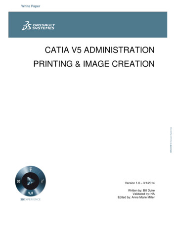
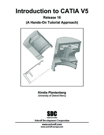
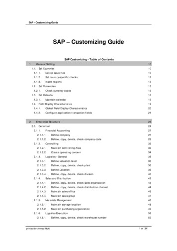
White PaperFigure 2 shows the default standard directory for Windows workstations. All of the GeneralParameters Standards XML files are shown in this directory, as well as the sub-directoriesdrafting, dxf and generativeparameters.Figure 3 shows the contents of the default drafting sub-directory for Windows. All of theDrafting Standards are stored in this sub-directory.Figure 3 - Default drafting sub-directory - WindowsFigure 4 shows the contents of the default dxf sub-directory for Windows. The DXF/DWGStandards are stored in this sub-directory.73DS.COM Dassault SystèmesFigure 2 - Default standard directory - Windows
White PaperFigure 4 - Default dxf sub-directory - Windows3DS.COM Dassault SystèmesFigure 5 shows the contents of the default generativeparameters sub-directory forWindows. The Generative View Styles Standards are stored in this sub-directory.Figure 5 - Default generativeparameters sub-directory - WindowsThe AIX directory structure is the same as that of Windows except for the default path name.Since V5R21 is only supported on UNIX for AIX (for servers only), this directory is:/usr/DassaultSystemes/B21/aix a/resources/standard.8
White Paper2. Customizing the CATIA V5 StandardsIn order to modify the CATIA V5 Standards, four steps must be taken. The first step is todefine the environment variables needed to edit the Standards. After these variables aredefined, then their supporting directory structure needs to be created. Once these first twosteps are done, the Standard Definitions must be accessed in CATIA V5 admin mode.Finally, the default Standards must be selected, modified, and saved in the appropriatecustomized Standards directory.The following sections provide detailed procedures for performing these four steps.2.1.Define Environment VariablesThere are two environment variables that must be set up in the CATIA Environment Editor:CATCollectionStandard (discussed earlier) and CATReferenceSettingPath.To define the values for the CATCollectionStandard and CATReferenceSettingPathenvironment variables, use the Environment Editor, as follows: For Windows, as a user with Administrator authority, the Environment Editor isstarted using: Start - All Programs - CATIA - Tools - Environment EditorFor AIX, as root, the Environment Editor is started by issuing the following command:/usr/DassaultSystemes/B21/aix a/code/command/catstart -run CATIAENVOnce the Environment Editor Window opens, select OK for the AdministratorWarning Message.If there is more than one environment defined, select the one that you will work with,and select OK again for the Administrator Warning Message.For the environment variable that needs to be modified (CATCollectionStandardand CATReferenceSettingPath), right-mouse-click on the variable name to accessits contextual menu, and then select Edit.Assign values to the environment variables, and make their path names meaningful.For example, define CATCollectionStandard as C:\CATIA\V5R21\standard (forWindows) or /CATIA/V5R21/standard (for AIX). For CATReferenceSettingPath,define it as C:\CATIA\V5R21\catlock (Windows) or /CATIA/V5R21/catlock (AIX).After making the modifications to the environment, save the changes by right-mouseclicking in the lower pane of the Environment Editor Window to access its contextualmenu, then select Save.Figure 6 shows the Environment Editor with these two variables added.93DS.COM Dassault SystèmesThe CATReferenceSettingPath variable defines the directory that stores the Administrator’sCATSettings files that are created when modifying CATIA settings in admin mode. This isalso the location for the storage of the locked CATSettings.
White Paper2.2.Create the Required DirectoriesOnce the environment variables CATReferenceSettingPath and CATCollectionStandardhave been defined, their directories need to be created. The structure forCATCollectionStandard should mimic the structure of the default Standards directoryCATDefaultCollectionStandard.Create the directory E:\CATIAV5\V5R21\CATLock (for Windows) or/CATIAV5/V5/CATLock (for AIX) to support the environment variableCATReferenceSettingPath.Also create E:\CATIAV5\V5R21\standard (for Windows) or /CATIAV5/V5R21/standard (forAIX) to support the environment variable CATCollectionStandard. Add the sub-directoriesdrafting, dxf and generativeparameters as needed based on the Standards that you planto customize. For example, this customized Standards structure for Windows would look likeFigure 7.Figure 7 - Customized Standard directory Structure - Windows103DS.COM Dassault SystèmesFigure 6 - V5R21 Environment Editor: variables defined (Windows)
White PaperTip: If the default Standard directory (defined by CATDefaultCollectionStandard) and theCustomized Standard directory (defined by CATCollectionStandard) both contain anidentically-named Standard, the Customized Standard will take precedence and will beused.2.3.Access of Standard Definitions in CATIA V5 adminmode3DS.COM Dassault SystèmesLog into CATIA and access the Standard Definitions using Tools - Standards. Because youdidn’t log into CATIA in admin mode, you will only be able to view the Standards. TheStandard values are not editable (they are “grayed-out”), and the Save As New icon is notselectable. This is shown in Figure 8.Figure 8 - Standard Definition Window - View ModeTo be able to edit (and save) the Customized Standards, you must log onto CATIA in adminmode. Since starting CATIA in admin mode has generated many questions at the TechnicalSupport Center, the following steps show the requirements for successfully doing this.To start CATIA in the admin mode, you must have Administrator/root authority, and you musthave the environment variable CATReferenceSettingPath set to a directory owned by theAdministrator/root.Windows:Open a command window and cd to the “unload directory”\code\bin directory. Forexample, for Windows 64-bit, cd to C:\Program Files\DassaultSystemes\B21\win b64\code\bin and issue the command:cnext -admin11
White PaperIf you have multiple environments, the -env flag must also be used to specify the correctenvironment:cnext -env CATIA.V5R21.B21 -adminAdditionally, if the directory path of the environment file is not the default(C:\ProgramData\DassaultSystemes\CATEnv for Windows 7 64-bit), the -direnv flag mustbe used:cnext -env CATIA.V5R21.B21 -direnv “C:\CATEnv” -adminAIX:In a UNIX window, cd to the “unload directory”/code/command directory. For example,cd to /usr/DassaultSystemes/B21/aix a/code/command and issue the command:./catstart -run “CNEXT -admin”Be sure to include the -env or -direnv flags if required, as noted above in the Windowsexample:./catstart -run CNEXT -env CATIA.V5R21.B21 -direnv /CATEnv -admin3DS.COM Dassault SystèmesOnce you log into CATIA in admin mode, the message shown in Figure 9 will appear:Figure 9 - Admin mode acknowledgementAfter logging into CATIA in admin mode, re-access the Standard Definitions (Tools Standards) and you will see that the Standard values are now editable, and the Save AsNew icon is now selectable. This is shown in Figure 10.12
White PaperFigure 10 - Standard Definition Window - Edit ModeSelect a default Standard – Modify and SaveAs mentioned earlier, the XML file names of the General Standards cannot be modified orcustomized. The Drafting Standards, DXF/DWG Interface Parameters and GenerativeParameters can have customized XML file names.If you want to change one of these standards, in the Standard Definition window (whilelogged into CATIA in admin mode) you would select category type, and start with an existingstandard file. Make the required changes, and then select Save As New with a new nameand it will be saved in the directory specified by the CATCollectionStandard variable. Thenew standard will be shown in the standard selection list as shown in Figure 11.Figure 11 - New Customized Standard133DS.COM Dassault Systèmes2.4.
White PaperIf you want to change one of the General Standards, you will need to copy the file for thedesired standard from the directory defined by CATDefaultCollectionStandard into thedirectory defined by CATCollectionStandard. If you modify the name, the file will not berecognized by CATIA, and the default one (without the modifications) will be used. Next,manually edit the copy of the XML file to make the desired changes. If theCATStdMechanicalDesign.xml file is not in the CATDefaultCollectionStandard directory,then you didn’t copy it from the “install folder”\startup\templates directory as discussedon Page 5 of this document. Log into CATIA in admin mode, and select Tools - Standards to open the StandardDefinition windowUnder Category select drafting.Under File, select the International Standard that is closest in content to yourcompany’s requirements (ANSI.xml, ASME.xml, ISO.xml )Expand the Standard Tree and edit the category that needs to be modifiedIn the example shown in Figure 12, the Dimension Line: Gap around unframedvalue is being changedContinue through all categories in which your company varies from the selectedInternational Standard and make the required modifications.Select the Save As New button and key a new name. This will save the newStandard in the drafting folder designated in the CATCollectionStandard.In this example, the Standard was saved as Company A.xmlFigure 12 - New Drawing Window showing the New Drafting StandardWhen a new Drawing is created, or when File - Page Setup is used to change the drawing’sStandard, this new Standard will be available as one of the selectable Standards as shownin Figure 13.143DS.COM Dassault SystèmesSince the Drafting Standards are unique, the following steps are used to create a newcompany Drafting Standard:
White PaperFigure 13 - New Drawing Window showing the New Drafting Standard3.1.Tips for Defining Drafting Standards DirectoriesMany customers who modify the CATIA Standards only modify the Drafting Standards. Atypical mistake that is made when attempting to perform this modification is an incorrectdefinition of the environment variable CATCollectionStandard. The problem occurs whenthe variable is set up to point to the drafting sub-directory instead of to the standarddirectory: e.g., it has been set to E:\CATIAV5\V5R21\standard\drafting when it should beset to E:\CATIAV5\V5R21\standard3.2.Tips for Controlling Multiple Customized DraftingStandardsIf you have multiple CATIA environments in order to support different projects or customers,each having a unique requirement for Drafting Standards, you will likely want a method forenforcing use of the correct Drafting Standard for each environment. To do this, the followingthree steps should be taken:1. Set unique values for the variables CATReferenceSettingPath andCATCollectionStandard in each environment, and create the directory structures tosupport these variables.2. Create new Drafting Standards for each environment, and save the XML files intoCATCollectionStandard, in the drafting sub-directory. An alternative to buildingyour own customized Drafting Standard is to obtain a copy of your customer’sDrafting Standard XML file, and place it into CATCollectionStandard drafting subdirectory.153DS.COM Dassault Systèmes3. Managing the CATIA V5 Standards
White Paper3. Make the Default Drafting Standard XML files unavailable in the default drafting subdirectory:On Windows 64-bit: Move all the XML files in the directoryC:\Program Files\Dassault Systemes\B21\win b64\resources\standard\draftingto:C:\Program Files\DassaultSystemes\B21\win b64\resources\standard\drafting\originalDoing this keeps the original Standard files available for future reference, but makesthem unavailable to interactive CATIA.3DS.COM Dassault SystèmesOnce these three steps have been followed, the user will only see the CustomizedStandards that are available in the CATCollectionStandard directory when creating a newCATIA Drawing. This is shown in Figure 14. The only selectable Standard available in thisexample is the new Standard Company A.xml. This prevents an incorrect DraftingStandard from being used.Figure 14 - New Drawing Window showing ONLY the New Drafting Standard3.3.Editing the Standard XML files using a Text EditorAll standard XML files can be edited using a text editor instead of using the CATIAinteractive editor. But, whenever possible, edit the standards using the CATIA interactiveeditor instead of a text editor because it is an easy-to-use graphical editor that allows thevalues to be edited correctly.To start, place a copy the required XML file from the directory defined byCATDefaultCollectionStandard into the directory defined by CATCollectionStandard. Editthis file to show the contents. Search through the large file and find the attribute and changethe value to the desired quantity. Save the file, and the change will be applied to the nextCATIA document that is created. Figure 15 shows the ANSI.xml file with the attributes forvalue of the Dimension Value: Vertical Justification (as shown back in Figure 10).16
White Paper3.4.Updating Standards from previous CATIA LevelsWith each new release of CATIA, the default Standards may change, with the addition andmodification of some parameters, as well as new functionality being introduced. Because ofthese changes, the Standards XML files might not be upward compatible. If you havecustomized your Standards in previous levels of CATIA and want to use the customization inthe current level, the XML files may need to be upgraded.If you have customized non-drafting Standard files, you must re-customize them by startingwith the new release level default Standards files, and editing the Standard to reflect yourdesired changes.For the Drafting Standards, if you have customized only a small number the parameters, itmay be easier to start with the new release level Standards files and re-customize them. Ifyou have many customizations made for your Drafting Standards, then it may be easiest touse a batch utility to generate current XML files based on your customized Drafting XML filesfrom the previous release. The batch utility CATAnnStandardTools provided with CATIAallows this conversion of the Drafting Standards only.To upgrade the Drafting Standard XML files to the current version, issue one of the followingcommands:CATAnnStandardTools UPGRADE ALL “directory for upgraded XML files”CATAnnStandardTools UPGRADE XXX “directory for upgraded XML files”where XXX is the Drafting Standard name (such as Company A.xml)173DS.COM Dassault SystèmesFigure 15 - CATStdMechanicalDesign.xml File (Partially shown)
White PaperWhen running this batch tool with the UPGRADE ALL argument, it searches for all of theDrafting Standard XML files in the drafting directories specified by the environment variablesCATDefaultCollectionStandard and CATCollectionStandard. It then converts them to theupgraded XML file format, and places a copy in the directory specified.When the UPGRADE XXX argument is used, the batch tool searches for the specific XMLfile in the Drafting Standard XML files in the drafting directories specified by the environmentvariables CATDefaultCollectionStandard and CATCollectionStandard. The tool thenconverts the XML file to the updated XML file format, and places a copy in the directoryspecified.For Windows, this command is executed in a command window from the directoryC:\Program Files\Dassault Systemes\B21\win b64\code\binFor AIX, in a UNIX window cd to the directory/usr/DassaultSystemes/B21/aix a/code/command and execute one of the followingcommands:./catstart -run CATAnnStandardTools UPGRADE XXX “directory for upgraded XMLfiles”where XXX is the Drafting Standard name (such as Company A.xml)183DS.COM Dassault Systèmes./catstart -run CATAnnStandardTools UPGRADE ALL “directory for upgraded XMLfiles”
White Paper3.5.“Tools – Options” for controlling StandardsTo further constrain the user’s ability to modify the Drafting and DXF Standards based onyour company’s requirements, some of the Options under Tools - Options can be set andlocked. To be able to lock the settings under Tool - Options, you must log onto CATIA inadmin mode. The following two sections show the options available for these two Standards.3.5.1.Drafting Standards Settings3DS.COM Dassault SystèmesThese options are accessed under Tools - Options - Mechanical Design - Drafting Administration, and are shown in Figure 16.Figure 16 - Tools - Options for locking the Drafting Standards19
White Paper3.5.2.DXF/DWG Standards Settings3DS.COM Dassault SystèmesThese options are accessed under Tools - Options - General - Compatibility - DXF, andare shown in Figure 17.Figure 17 - Tools - Options for locking the DXF/DWG Standards4. Sharing of Customized CATIA V5 StandardsWhen a CATIA document is created, the values of the parameters defined by the Standardsin use at the time of the document creation are copied into the document. Since eachdocument contains a copy of the Standards, the document is considered a standalonedocument, which allows it to be exchanged with other users, projects and companies,without having to send the Standards files along with the document.If there is a need to create CATIA documents using a specific Standard, then using a newStandards file can be customized as outlined in this paper, or a copy of an alreadyCustomized Standard files can be obtained and placed into the directory structure defined bythe environment variable CATCollectionStandard.20
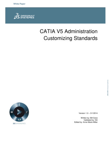
White Paper3DS.COM Dassault SystèmesOnce the directory structure for Standards has been created on a network accessibledirectory on one workstation, the directory structure can be set up as a Shared directory onWindows Workstations or a NFS exported directory on AIX workstations. An example of adirectory structure for supporting multiple environments is shown in Figure 18. Here we seethat each environment contains a sub-directory under the V5R21 folder, and has a namethat is based on the company name. Each of these Company directories contains aCATLocks sub-directory for holding the locked CATSettings for the environment, and astandard sub-directory, for holding the necessary Standards for the environment. In thisexample, Company A & Company B only have customized Drafting Standards, whileMy Company has customized Standards for Drafting, DXF/DWG, and GenerativeParametersFigure 18 – XML Directory structure for Multiple EnvironmentsOn the Client workstations, this directory structure can be mapped for Windows, or NFSmounted for AIX. Each of the Clients must have different CATIA environments defined foreach Company. In each environment, the environment variablesCATReferenceSettingPath and CATCollectionStandard point to the appropriate mappeddirectory for Windows workstations, or to the appropriate NFS mounted directory for AIXworkstations.21
White Paper5. ConclusionThe ability to keep your company’s CAD/CAM systems properly administered is an importantpart of your business. Learning how to modify and manage the default Standards providedwith CATIA allows you to be able to work with your own Standards as well as the Standardsof your customers.It can be seen in this paper that there are several different types of Standards, which controlthe element properties within CATIA Documents. After understanding the different types,
The CATIA V5 Standards define default values for the element properties within CATIA. Although CATIA can be use out of the box with the Standards defined by Dassault Systèmes, many companies do customize these Standards, to meet their needs and the needs of their suppliers. Because of this, it