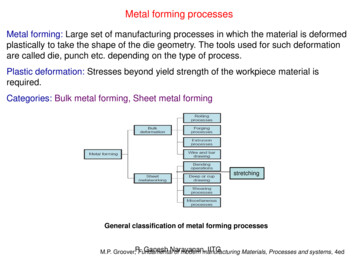
Transcription
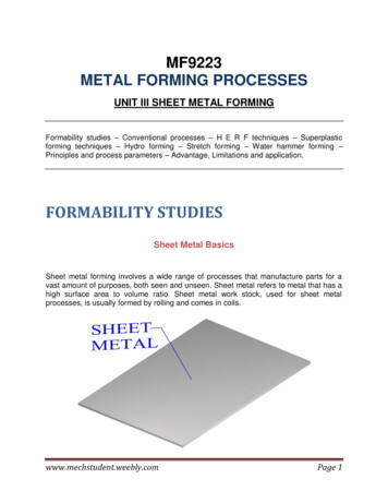
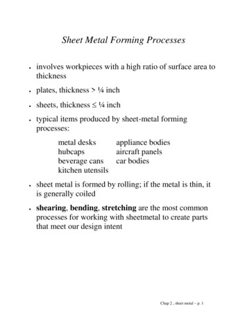
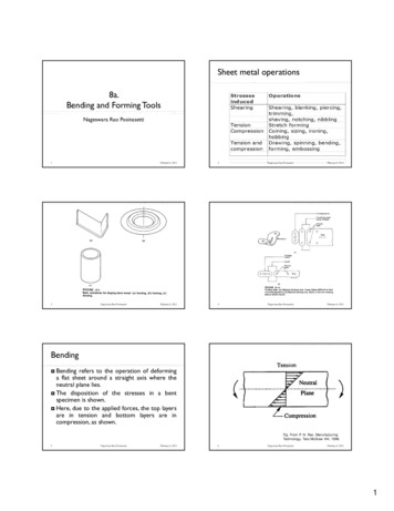
Sheet metal operations8a.Bending and Forming ToolsNageswara Rao Posinasetti13Nageswara Rao PosinasettiFebruary 6, 20122Nageswara Rao PosinasettiFebruary 6, 2012February 6, 20124Nageswara Rao PosinasettiFebruary 6, 2012BendingBending refers to the operation of deforminga flat sheet around a straight axis where theneutral plane lies. The disposition of the stresses in a bentspecimen is shown. Here, due to the applied forces, the top layersare in tension and bottom layers are incompression, as shown. Fig. From P. N. Rao, ManufacturingTechnology, Tata McGraw Hill, 1998.5Nageswara Rao PosinasettiFebruary 6, 20126Nageswara Rao PosinasettiFebruary 6, 20121
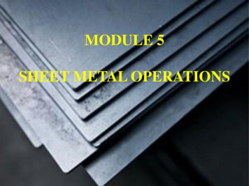
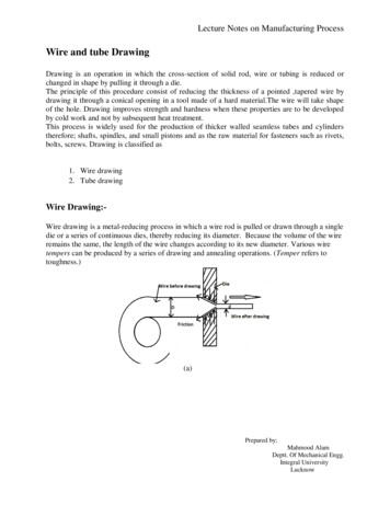
BendingThe plane with no stresses is called theneutral axis. The neutral axis should be at thecentre when the material is elasticallydeformed. But when the material reaches the plasticstage, the neutral axis move downward, sincethe materials oppose compression muchbetter than tension. Fig. From P. N. Rao, ManufacturingTechnology, Tata McGraw Hill, 1998.7Nageswara Rao PosinasettiFebruary 6, 2012Bend allowance 8Increased length of the sheet because ofbending Nageswara Rao PosinasettiFebruary 6, 201210Bend allowance, B ( R K t )Where bend angle, radiansR inside radius of the bend, mmK location of neutral axis from bottom surface 0.33 when R 2 t 0.50 when R 2 tt sheet thickness, mmNageswara Rao PosinasettiFig. From Dr. John G. Nee(revised by), Fundamentalsof Tool Design, FourthEdition, 1998, SME11Nageswara Rao PosinasettiFebruary 6, 2012Bending 9Nageswara Rao PosinasettiFebruary 6, 2012February 6, 2012Fig. From Dr. John G. Nee(revised by), Fundamentalsof Tool Design, FourthEdition, 1998, SME12Nageswara Rao PosinasettiFebruary 6, 20122
Fig. From Dr. John G. Nee(revised by), Fundamentalsof Tool Design, FourthEdition, 1998, SME13Nageswara Rao PosinasettiFebruary 6, 2012Fig. From P. N. Rao, ManufacturingTechnology, Tata McGraw Hill, 1998.14Nageswara Rao PosinasettiFebruary 6, 2012Since R 2 t , K 0.33 Bend allowance 9.42 mm Since R 2t , K 0.50 Bend allowance 18.06 mmTotal length 50 - (5 3) 9.42 100 - (10 3) 18.06 50 - (10 3) 185.48mmFig. From Dr. John G. Nee(revised by), Fundamentalsof Tool Design, FourthEdition, 1998, SME15Nageswara Rao PosinasettiFebruary 6, 201216Nageswara Rao PosinasettiFebruary 6, 201217Nageswara Rao PosinasettiFebruary 6, 201218Nageswara Rao PosinasettiFebruary 6, 20123
Fig. From P. N. Rao, ManufacturingTechnology, Tata McGraw Hill, 1998.19Nageswara Rao PosinasettiFebruary 6, 201220Nageswara Rao PosinasettiFig. From P. N. Rao, ManufacturingTechnology, Tata McGraw Hill, 1998.Fig. From P. N. Rao, ManufacturingTechnology, Tata McGraw Hill, 1998.21Nageswara Rao PosinasettiFebruary 6, 2012February 6, 201222Nageswara Rao PosinasettiFebruary 6, 2012Bend radius 23Nageswara Rao PosinasettiFebruary 6, 201224The outer layers which are under tension should notbe stretched too much, otherwise there is likelihoodof rupture taking place.The amount of stretching depends on the sheetthickness and the bend radius.Lower the bend radius, higher is the strain in thiszone.Hence there is a minimum bend radius to bespecified, depending on the material characteristics.Nageswara Rao PosinasettiFebruary 6, 20124
Bend radius Bending forceMinimum bend radius 0.5 t soft materials t other materials 3.0 t spring materials.25Nageswara Rao Posinasetti 27 February 6, 201226Nageswara Rao PosinasettiFebruary 6, 2012Estimate the force required for a 90 deg bending ofSt 50 steel of thickness 2 mm in a V die. The dieopening can be taken as eight times the thickness.The length of the bent part is 1 m.Where Fb bending force, tonsK 1.33 for die opening of 8t 1.20 for die opening of 16t 0.67 for U bending 0.33 for a wiping dieL length of the bent part, ins ultimate tensile strength, lb/in2.t blank thickness, inW width between the contact points, in 8t for V-bendsNageswara Rao PosinasettiThe bending load may be calculated from theknowledge of material properties and the diecharacteristics as shown below:Die opening, W 8 2 16 mm. Ultimate tensile strength 500 MPa. Bending force 166.25 kN February 6, 2012Calculate the bending force required for aC50 steel 1.5 mm sheet of width 1 m to bebent in a wiping die. The die radius used is 3mm. C50 steel, ultimate tensile strength can betaken as 800 MPa. 28Nageswara Rao PosinasettiFebruary 6, 2012Die opening,W 1.5 3 3 7.5 mmFor a wiping die, K 0.33Bending force 79.20 kN29Nageswara Rao PosinasettiFebruary 6, 201230Nageswara Rao PosinasettiFebruary 6, 20125
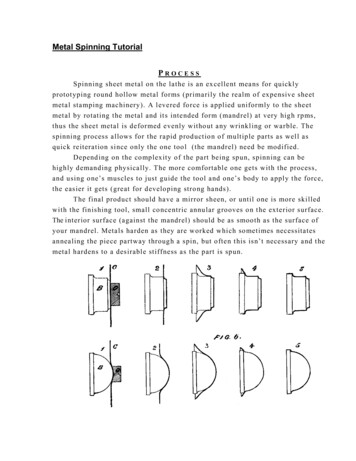
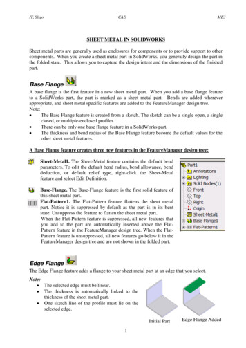
Bending direction Grain orientationAs far as possible, the bending is to be done in adirection perpendicular to the grain direction in themetal.By virtue of the rolled sheets being used for bending,the grain direction usually is along the length axis,being the direction of rolling. There is a possibility ofcracks appearing at the time of bending if the bendingis done along the grains.Fig. From P. N. Rao, ManufacturingTechnology, Tata McGraw Hill, 1998.31Nageswara Rao PosinasettiFebruary 6, 2012Bending direction 32But if two bendings are to be done on thesame sheet at right angles, then it may bedesirable to make them at 45 deg to the graindirection so that the risk of cracking isminimised.Nageswara Rao PosinasettiFebruary 6, 2012Spring back 33Nageswara Rao PosinasettiFebruary 6, 201234One of the principal concerns in bending is thespring back of the metal.Spring back in bending is difficult to estimatetheoretically. But it is essential to compensate it,because the bend geometry gets affected by thespring back directly.The data relating to the most generally usedconfigurations are available in handbooks.Nageswara Rao PosinasettiFebruary 6, 2012Fig. From Dr. John G. Nee(revised by), Fundamentalsof Tool Design, FourthEdition, 1998, SME35Nageswara Rao PosinasettiFebruary 6, 201236Nageswara Rao PosinasettiFebruary 6, 20126
Forming diesSolid form diesFor parts Made of soft metal such as pipestrap Male and female templates are used. Fig. From Dr. John G. Nee(revised by), Fundamentalsof Tool Design, FourthEdition, 1998, SME37Nageswara Rao PosinasettiFebruary 6, 201238Solid form dieFig. From Dr. John G. Nee(revised by), Fundamentalsof Tool Design, FourthEdition, 1998, SME39Nageswara Rao PosinasettiFebruary 6, 2012Nageswara Rao Posinasetti40February 6, 2012Fig. From Dr. John G. Nee(revised by), Fundamentalsof Tool Design, FourthEdition, 1998, SMENageswara Rao PosinasettiFebruary 6, 2012Forming dies with Pressure pad For small radius corners41Nageswara Rao PosinasettiFor accurate diesFig. From Dr. John G. Nee(revised by), Fundamentalsof Tool Design, FourthEdition, 1998, SMEFebruary 6, 201242Nageswara Rao PosinasettiFebruary 6, 20127
Fig. From Dr. John G. Nee(revised by), Fundamentalsof Tool Design, FourthEdition, 1998, SME43Nageswara Rao PosinasettiFebruary 6, 2012Fig. From Dr. John G. Nee(revised by), Fundamentalsof Tool Design, FourthEdition, 1998, SME44Nageswara Rao PosinasettiFig. From Dr. John G. Nee(revised by), Fundamentalsof Tool Design, FourthEdition, 1998, SME45Nageswara Rao PosinasettiFebruary 6, 2012February 6, 2012Fig. From Dr. John G. Nee(revised by), Fundamentalsof Tool Design, FourthEdition, 1998, SME46Nageswara Rao PosinasettiFebruary 6, 2012Using Rubber and UrethaneFig. From Dr. John G. Nee(revised by), Fundamentalsof Tool Design, FourthEdition, 1998, SME47Nageswara Rao PosinasettiFebruary 6, 201248Nageswara Rao PosinasettiFebruary 6, 20128
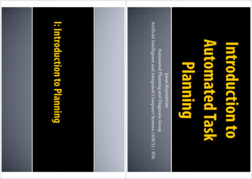
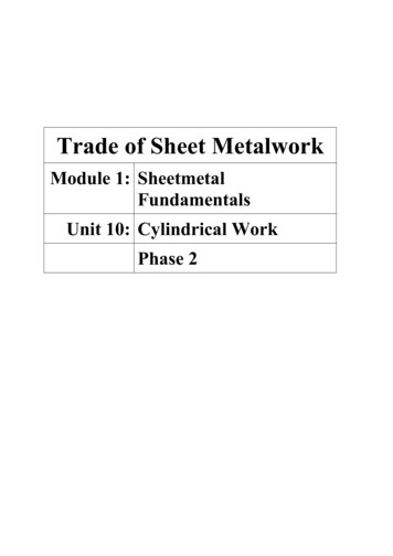
EmbossingEmbossingEmbossing is the operation used in makingraised figures on sheets with its correspondingrelief on the other side. The process essentially involves drawing andbending of the metal. An example of the embossing operation isshown. 49Nageswara Rao PosinasettiFebruary 6, 2012 The die set consists essentially of a die and punchwith the desired contours, so that when the punchand die meet the clearance between them is same asthat of the sheet thickness.Embossing operation is generally used for providingdimples on sheets to increase their rigidity and fordecorative sheet work used for panels in houses andreligious places.50Nageswara Rao PosinasettiFebruary 6, 2012CoiningCoining is essentially a cold forging operationexcept for the fact that the flow of the metaloccurs only at the top layers and not theentire volume. The coining die consists of the punch and diewhich are engraved with the necessary detailsrequired on both sides of the final object. Fig. From Dr. John G. Nee(revised by), Fundamentalsof Tool Design, FourthEdition, 1998, SME51Nageswara Rao PosinasettiFebruary 6, 201252Nageswara Rao PosinasettiFebruary 6, 2012Coining 53EmbossingThe pressures involved in coining are very high, ofthe order of 1600 MPa because of the very finedetails that are normally desired in coining.The type of impression obtained on both sides wouldbe different unlike the embossing.Coining is used for making coins, medals and similararticles, and for impressions on decorative items.Nageswara Rao PosinasettiFebruary 6, 201254Nageswara Rao PosinasettiFebruary 6, 20129
CoiningFig. From Dr. John G. Nee(revised by), Fundamentalsof Tool Design, FourthEdition, 1998, SME55Nageswara Rao PosinasettiFebruary 6, 201256Nageswara Rao PosinasettiFig. From Dr. John G. Nee(revised by), Fundamentalsof Tool Design, FourthEdition, 1998, SME57Nageswara Rao PosinasettiFebruary 6, 2012Fig. From Dr. John G. Nee(revised by), Fundamentalsof Tool Design, FourthEdition, 1998, SME58Nageswara Rao PosinasettiFig. From Dr. John G. Nee(revised by), Fundamentalsof Tool Design, FourthEdition, 1998, SME59Nageswara Rao PosinasettiFebruary 6, 2012February 6, 2012February 6, 2012Fig. From Dr. John G. Nee(revised by), Fundamentalsof Tool Design, FourthEdition, 1998, SME60Nageswara Rao PosinasettiFebruary 6, 201210
Fig. From Dr. John G. Nee(revised by), Fundamentalsof Tool Design, FourthEdition, 1998, SME61Nageswara Rao PosinasettiFebruary 6, 201211
1 8a. Bending and Forming Tools Nageswara Rao Posinasetti 1 February 6, 2012 2 Nageswara Rao Posinasetti February 6, 2012 Sheet metal operations 3 Nageswara Rao Posinasetti February 6, 2012 4 Nageswara Rao Posinasetti February 6, 2012 Bending refers to the operation of deforming a fla