Transcription
EZCT-2000Ccurrent transformer test set
EZCT-2000Ccurrent transformer test setProduct OverviewThe EZCT-2000C is Vanguard’s third-generationmicroprocessor-based current transformer test set.Designed specifically for CT testing, the EZCT-2000Chas the following outstanding features that cangreatly increase productivity and save time duringthe commissioning stage: Performs CT excitation, current-ratio, polarity,and phase angle tests Measures insulation resistance and windingresistance of the CT secondary windings Measures the CT’s load burden Standalone or computer-controlled via USB orBluetooth wireless interfaceThe EZCT-2000C’s test leads can be connected to allthe CT output terminals, and the complete CT testcan be performed automatically without any operatorintervention.EZCT-2000C connectionsExcitation TestDemagnetizationThe CT excitation test is performed using theANSI/IEEE C57.13.1 test method. Test voltageranges from 50, 300, 500,1200 and 2000 Vaccan be selected for the excitation test. The testvoltage is raised and lowered automatically bythe EZCT-2000C. The excitation test voltageand current data is collected and stored in theunit's internal memory. Knee point voltages(ANSI 10/50, IEC 60044, IEC 61869, IEEE-30,and IEEE-45) are calculated and printed on thetest report. All of the test leads can be connected to the CT output terminals (X1, X2, X3,X4 and X5), and there is no lead switching required during testing. This convenient arrangement allows for testing any of the 10 possiblecombinations of X1 to X5. Up to 10 excitationtests can be stored in one record. Once the testis completed, the test report and CT excitationcurves can be printed on the built-in thermalprinter.The EZCT-2000C Plus automatically demagnetizes theCT under test when performing an excitation test.CT Winding InsulationResistance Test FeatureThe EZCT-2000C offers an IR test feature thatcan also measure the insulation resistance ofthe CT’s secondary winding using a test voltage up to 1000 Vdc. The DC winding resistancereading range is from 2 to 500 Mega-ohms. Theinsulation resistance test results are displayedand printed on the report.Winding Resistance TestThe EZCT-2000C can measure the DC resistance oftransformer windings from 100 micro-ohms to 10ohms.CT Burden TestThe EZCT-2000C can measure the CT’s actualconnected burden by injecting a 1A or 5A testcurrent into the load. The CT burden measurements(Voltage, current, Cos φ, and burden impedance)are displayed on the screen and printed on the testreport. This important test verifies the actual CTmeasured burden before putting the CT in service,thus avoiding any potential configuration conflicts.Current Ratio and PhaseError TablesAs part of the tabulated test results, the EZCT-2000Ccan also print the current ratio and current phaseerror tables.Current SourceThe EZCT-2000C offers a programmable currentsource (0-20A, 0-15Vac) that can be used to verifyCT loads. The on-time timer and output current aredisplayed on the LCD screen.Ratio and Polarity TestsThe CT current-ratio is determined using theANSI/IEEE C57.13.1 Section 8.1 measurementmethod. A test voltage is applied on any twoterminals (X1 to X5) of the CT, and the inducedvoltage is measured through the H1 and H2terminals of the CT. The CT current-ratio isdisplayed and also stored in memory. The current-ratio is measured from 0.8 to 5,000. TheCT winding polarity is displayed as a “ ” sign(in-phase) or a “-” sign (out-of-phase) and isannotated with the phase angle in degrees. TheCT current ratio error and phase displacementis also calculated based on the CT burden (orrated power) and rated current.2ordering informationPart No.Description9101-UC 110V EZCT-2000C, cables,and PC software9102-UC 220V EZCT-2000C, cables,and PC software9101-SC EZCT-2000C shipping caseTP4-CSTP4 thermal printer paper(24 rolls)
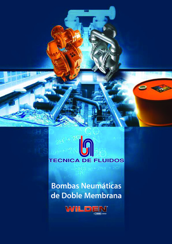
EZCT-2000C Featuresinsulationresistanceconnectorsconnectors forX terminalsconnectors forH terminalsground studbluetooth indicator5" back-lit LCD screen(240 x 128 pixels)AC current sourceconnectorspower switchUSB flashdrive interfaceUSB PC interfacetest voltagepresence indicator4.5” widethermal printeremergencyturn off switchrugged "QWERTY"membrane keypadTest Record Header InformationInternal Test Record StorageInternal Test Plan StorageTest record header information, including thecompany, substation name, circuit ID, manufacturer,mode, CT serial number, and the operator’s name,can be stored with each record. In addition to thetest record header, a 20-character test descriptionfor each test in the record (10 tests per record) canalso be entered.The EZCT-2000C can store up to 140 testrecords in Flash EEPROM. Each record maycontain up to 10 excitation curves, burden testreports, current ratio readings, and polarityand DC resistance readings. Test records canbe recalled and printed on the built-in thermalprinter. They can also be transferred to a PCusing the USB port, wirelessly via Bluetooth,or via the USB Flash drive interface port.The EZCT-2000C can store up to 128 CT test plansin Flash EEPROM. A test plan is comprised of theexcitation test voltage, current range selection, CTnameplate ratios, and CT winding terminal combinations (X1 to X5) for each test and also includes theinsulation test definition. Up to 10 test definitions canbe stored per test plan. The ability to store test plansmakes CT testing an extremely simple process. Toperform a test, the EZCT-2000C is connected to the CTterminals and a test plan is selected to run.User Interface and DisplayThe EZCT-2000C features a back-lit LCD screen (240x 128 pixels) that is clearly viewable in both brightsunlight and low-light levels. A "QWERTY"-stylemembrane keypad is used to enter test informationand to control the unit’s functions.Computer InterfaceThe EZCT-2000C Plus can be used as a stand-aloneunit or can be computer-controlled. It can be connected to a PC via the USB port or wirelessly viaBluetooth. In computer-controlled mode, using theincluded CT Analysis Software, test records can bedownloaded from the unit’s memory, or CT tests canbe run from the PC. Test plans can also be createdwith the provided software. A test plan defines thevarious test parameters (test voltage, current range,nameplate ratios, etc.) and can be used to quicklyperform tests. Additionally, tabulated test recordsare automatically exported to PDF, Excel, and XMLformats for further analysis.External Data StorageThe EZCT-2000C features a USB Flash driveinterface that makes it very convenient tostore and transfer test records and test plans.By using a USB Flash drive, test records andtest plans can be quickly transferred betweena computer and the EZCT-2000C without theneed to connect the unit to the computer.Built-in Thermal PrinterCreating test plans for the EZCT-2000C is also asimple process. A test plan can be created usingthe EZCT-2000C’s keypad or can be created on a PC(with provided software) and then downloaded to theEZCT-2000C via the USB port or Bluetooth. For addedconvenience, test plans can also be copied from aUSB Flash drive to the EZCT-2000C via the USB Flashdrive interface.typical test results screenA built-in 4.5” wide thermal printer can printthe current transformer test report and plotthe excitation curves.3
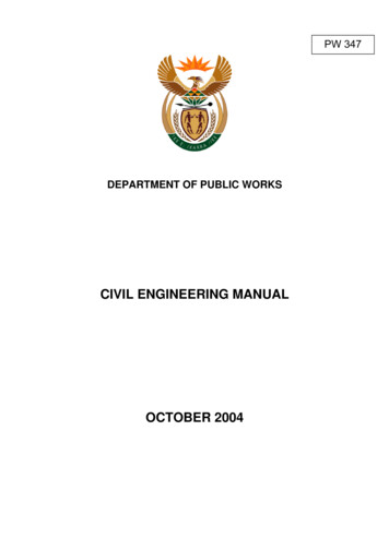
EZCT-2000C thermal printer outputtypical burden test resultstypical insulation resistance test resultsEZCT-2000C desktop printer output4
EZCT-2000C desktop printer outputEZCT-2000Ctechnical specificationsphysicalDimensions: 19"W x 13"H x 16"D (48.3 cm x 33cm x 40.1 cm)specifications Weight: 73 lbs. (33.1 Kg)inputpower100 120 Vac or 200 240 Vac(factory pre-set), 50/60 Hzcurrent ratiorange0.8 999: 0.1%, 1000 1999: 0.3%, 2,000 4,999: 1%,5,000 10,000: 1.5%measuringmethodIEC 60044-1, IEC 61869, ANSI/IEEE C57.13.1,and ANSI/IEEE C57.12.90output testvoltages0 50 Vac @ 10A max; 0 300 Vac @ 10A max; 0 500 Vac @5A max; 0 1200 Vac @ 2A max ; 0 2000 Vac @ 1A maxcurrentsource1 20A @ 0 15 Vac;displays test current and current on-timeresistance100 micro-ohms 30 ohms; accuracy: 2% of reading 1 count, 10reading range micro-ohmsinsulation2 M-ohms 500 M-ohms; accuracy: 3%resistance test of reading; 500 1,000 Vdc test voltagevoltage0 2,200 Vacreading range accuracy: 1.0% of reading, 1 voltcurrentreading range0 10 A, accuracy: 1.0% of reading, 0.02Adisplay5" back-lit LCD screen (240 x 128 pixels)viewable in bright sunlight and low-light levelsphase anglemeasurement0 360 degreesaccuracy: 1.0 degreeprinterbuilt-in 4K” wide thermal printercomputerinterfacesone USB port and bluetooth wirelessinterfacepcsoftwareWindows -based CT analysis software is included with purchase priceexternaldata storageone USB flash drive interface port (flashdrive not included)100010110internal teststores 140 test records. Each test record may contain up to 10 sets of excitation, resistance and ratio datarecord storage100010110internal testplan storagestores 128 test plans. Each test plan can store 10 excitation test voltageand current settingstemperatureOperating: -10 C to 50 C ( 15 F to 122 F)Storage: -30 C to 70 C (-22 F to 158 F)cablesOne 20-foot (6.10m) cable set (X1-X5), one 35-foot (10.69m) H cable set, current source cables, insulation test cables, power cord, ground cable,USB cable. A transportation case is included with the purchase price2,000 m (6,562 ft)warrantyone year on parts and laborto full safety specificationsaltitude!safetydesigned to meet UL 61010A-1 and CAN/CSA C22.2 No. 1010.1-92 standardshumidity90% RH @ 40 C (104 F)non-condensingNOTE : the above specifications are valid at nominal voltage and ambient temperature of 25 C ( 77 F). Specifications are subject to change without notice.5
Instruments designed and developedby the hearts and minds of utilityelectricians around the world.Founded in 1991 and located in Ontario, California, USA, Vanguard InstrumentsTM offersa wide range of diagnostic test equipment that accurately and efficiently measures thehealth of critical substation equipment, such as transformers, circuit breakers, andprotective relays.Our first product was a computerized, extra high voltage (EHV) circuit breaker analyzer,which became the forerunner of an entire line of EHV circuit breaker test equipment.Over the years, our portfolio has grown tremendously to include microcomputer-basedprecision micro-ohmmeters; single- and three-phase transformer winding turns-ratiotesters; transformer winding-resistance meters; mega-ohm resistance meters; and avariety of other application-specific products.Our instruments are rugged, reliable, accurate, and user friendly. They eliminatetedious and time-consuming operations, while providing fast, complex test-resultcalculations. Using our equipment helps reduce errors and eliminates the need tomemorize long sequences of procedural steps.In 2017, Vanguard Instruments became a part of Doble Engineering Company, anenergy industry leader in hardware, software, and services that diagnose and monitorthe health of critical assets.1520 S. Hellman AvenueOntario, California 91761, USAPhone 909-923-9390 Fax 909-923-9391www.vanguard-instruments.comRevision F. March 16, 2018 Copyright 2018 Doble Engineering Company
The CT excitation test is performed using the ANSI/IEEE C57.13.1 test method. Test voltage ranges from 50, 300, 500,1200 and 2000 Vac can be selected for the excitation test. The test voltage is raised and lowered automatically by the EZCT-2000C. The excitation test voltage and current da