Transcription
Practical Solution Guideto Arc Flash HazardsSECOND EDITIONCourtesy ofEasyPower, LLCdevelopers of Conrad St. PierreSatish Shrestha, PEAfshin Majd, PhD, PEDavid Castor, PEChet DavisRobert Luo, PhDMike Koch
ii
Practical Solution GuideTo Arc Flash HazardsSECOND EDITIONAUTHORSConrad St. PierreSatish Shrestha, PEAfshin Majd, PhD, PEDavid Castor, PEChet DavisRobert Luo, PhDMike KochEDITORSTed BalderreeStephen DriggarsMichael MezaCover image courtesy of Salisbury by HoneywellCopyright 2015 by EasyPower, LLCPublished by EasyPower, LLCFirst edition was published and copyrighted in 2002ISBN 978-0-9971026-0-4All rights reserved. No part of this publication may be reproduced, distributed, ortransmitted in any form or by any means, including photocopying, recording, orother electronic or mechanical methods, without the prior written permission of thepublisher, except in the case of brief quotations embodied in critical reviews andcertain other noncommercial uses permitted by copyright law.EasyPower, LLC7730 SW Mohawk St, Tualatin OR 97062www.easypower.comiii
ForwardFORWARDEasyPower, LLC is pleased to bring you the Second Edition of the “Practical SolutionGuide to Arc Flash Hazards.” This edition has been fully updated to reflect the mostrecent changes in standards and practices. We believe this will be a valuable tool forelectrical engineers, safety managers, or anyone responsible for implementing andmaintaining an arc flash hazard safety program.The guide was designed to walk you through the necessary steps of implementing anarc flash assessment as part of your overall safety program requirements. It will help youand your team make important decisions concerning the safety of your employees andhelp manage the complex tasks of OSHA and NFPA 70E compliance for arc flash hazards.Arc flash hazard analysis and the development of safety programs to protect againstarc flash hazards is still in its infancy. Research into the arcing phenomena is ongoingas the industry tries to better understand and model arcing faults. Standards andrecommended practices are changing constantly to reflect these new understandingsand to better protect workers. Personal protective equipment (PPE) is also changing ata rapid pace as new and better tech nology is developed. EasyPower, LLC has created anArc Flash Resource Center at the website www.easypower.com to keep you up-to-dateas new information becomes available and industry advancements are made. Look fornew versions of this guide as we continue to enhance and add new tech nology to thearc flash assessment process.EasyPower, LLC is committed to providing the industry with the most advanced state-ofthe-art tech nology in our EasyPower software product line. We believe the EasyPowersoftware provides the self-documenting solution capabilities to keep your safetyprogram current and in compliance with OSHA and NFPA 70E standards. EasyPower,LLC can also provide detailed engineering studies and arc flash assessment programs tohelp your company get started.We hope that the “Practical Solution Guide to Arc Flash Hazards” becomes a valuedresource to your library.iv
Practical Solution Guide to Arc Flash HazardsDISCLAIMERWarning - Disclaimer: The calculation methods listed in the book are based on theoreticalequations derived from measured test results. The test results are a function of specifichumidity, barometric pressure, temperature, arc distance, and many other variables.These parameters may not be the same in your facility or application. The resultscalculated from these equations may not produce conservative results when applied toyour facility. PPE recommended by any calculation method will NOT provide completeprotection for all arc hazards. Injury can be expected when wearing recommended PPE.The results should be applied only by engineers experienced in the application of arcflash hazards. The authors make no warranty concerning the accuracy of these results asapplied to real world scenarios.Arc flash as given in NFPA 70E and IEEE Std 1584 -2002 is concerned with personalinjury when a worker is near or working on energized equipment. Working on energizedconductors should only be done when it is impossible to shut down the equipment.This book does not condone working on energized equipment.Using the methods in NFPA 70E or IEEE Std 1584 does not insure that a worker will notbe injured by burns from an arc-flash. Following the NFPA 70E and IEEE 1584 proceduresand wearing the proper protective equipment will greatly reduce the possibility ofburns.v
Table of Contentsvi
Practical Solution Guide to Arc Flash HazardsTABLE OF CONTENTSChapter 1 Introduction . . . . . . . . . . . . . . . . . . . . . . . . . . . . . . . . . . . . . . . . . . . . . . . . . . . . . . . 1Chapter 2 Concepts and Definitions For Arc Flash Risk Assessment. . . . . . . . . . . . . . 3Causes of Electric Arcs. . . . . . . . . . . . . . . . . . . . . . . . . . . . . . . . . . . . . . . . . . . . . . . . . . . . . . . . . 4The Nature of Electrical Arcs . . . . . . . . . . . . . . . . . . . . . . . . . . . . . . . . . . . . . . . . . . . . . . . . . . . 5Hazards of Arcing Faults. . . . . . . . . . . . . . . . . . . . . . . . . . . . . . . . . . . . . . . . . . . . . . . . . . . . . . . 6Probability of Survival. . . . . . . . . . . . . . . . . . . . . . . . . . . . . . . . . . . . . . . . . . . . . . . . . . . . . . 6Impacts of Arc Flash. . . . . . . . . . . . . . . . . . . . . . . . . . . . . . . . . . . . . . . . . . . . . . . . . . . . . . . . . . . 7Potential Exposure to Arc Flash . . . . . . . . . . . . . . . . . . . . . . . . . . . . . . . . . . . . . . . . . . . . . . . . 7Developments in Addressing Arc Flash Hazard . . . . . . . . . . . . . . . . . . . . . . . . . . . . . . . . . 8Chapter 3 Arc Flash Calculation and NFPA Methods . . . . . . . . . . . . . . . . . . . . . . . . . . . 11IEEE Std 1584-2002. . . . . . . . . . . . . . . . . . . . . . . . . . . . . . . . . . . . . . . . . . . . . . . . . . . . . . . . . . . 12Step 1: Estimate of Arcing Current. . . . . . . . . . . . . . . . . . . . . . . . . . . . . . . . . . . . . . . . . 12Step 2: Estimate of Normalized Incident Energy. . . . . . . . . . . . . . . . . . . . . . . . . . . . 13Step 3: Estimate of Incident Energy. . . . . . . . . . . . . . . . . . . . . . . . . . . . . . . . . . . . . . . . 13Step 4: Flash-Protection Boundary. . . . . . . . . . . . . . . . . . . . . . . . . . . . . . . . . . . . . . . . . 14NFPA 70E Annex D. . . . . . . . . . . . . . . . . . . . . . . . . . . . . . . . . . . . . . . . . . . . . . . . . . . . . . . . . . . . 14Doughty Neal Paper (Annex D.3) . . . . . . . . . . . . . . . . . . . . . . . . . . . . . . . . . . . . . . . . . . 15DC Arc Flash Calculations (Annex D.5). . . . . . . . . . . . . . . . . . . . . . . . . . . . . . . . . . . . . . . . . 16Arc Blast Pressure. . . . . . . . . . . . . . . . . . . . . . . . . . . . . . . . . . . . . . . . . . . . . . . . . . . . . . . . . . . . . 17Electrode Orientation. . . . . . . . . . . . . . . . . . . . . . . . . . . . . . . . . . . . . . . . . . . . . . . . . . . . . . . . . 17Current-limiting Fuses. . . . . . . . . . . . . . . . . . . . . . . . . . . . . . . . . . . . . . . . . . . . . . . . . . . . . . . . 18Duration of the Arcs. . . . . . . . . . . . . . . . . . . . . . . . . . . . . . . . . . . . . . . . . . . . . . . . . . . . . . . . . . 20Estimated Incident Energy for Overhead Open Air Systems . . . . . . . . . . . . . . . . . . . . 21Chapter 4 Practical Steps to Arc Flash Calculations . . . . . . . . . . . . . . . . . . . . . . . . . . . . 27Introduction . . . . . . . . . . . . . . . . . . . . . . . . . . . . . . . . . . . . . . . . . . . . . . . . . . . . . . . . . . . . . . . . . 28Step 1 – Identify All Locations and Equipment for Arc Flash Hazard Assessment. 29Step 2 – Collect Data . . . . . . . . . . . . . . . . . . . . . . . . . . . . . . . . . . . . . . . . . . . . . . . . . . . . . . . . . 29Equipment Data for Short Circuit Analysis . . . . . . . . . . . . . . . . . . . . . . . . . . . . . . . . . 29Equipment Data For Protective Device Characteristics. . . . . . . . . . . . . . . . . . . . . . 30Equipment Data For Arc Flash Study. . . . . . . . . . . . . . . . . . . . . . . . . . . . . . . . . . . . . . . 30Determine All Possible Operating Conditions. . . . . . . . . . . . . . . . . . . . . . . . . . . . . . 31Step 3 – Prepare a One-line Diagram of the System. . . . . . . . . . . . . . . . . . . . . . . . . . . . 32Step 4 – Perform a Short Circuit Study. . . . . . . . . . . . . . . . . . . . . . . . . . . . . . . . . . . . . . . . . 33Calculate Bolted Fault Current. . . . . . . . . . . . . . . . . . . . . . . . . . . . . . . . . . . . . . . . . . . . . 33Calculate Contributing Branch Currents. . . . . . . . . . . . . . . . . . . . . . . . . . . . . . . . . . . .34Step 5 – Determine Expected Arc Current . . . . . . . . . . . . . . . . . . . . . . . . . . . . . . . . . . . . . 34Calculate Arc Current . . . . . . . . . . . . . . . . . . . . . . . . . . . . . . . . . . . . . . . . . . . . . . . . . . . . . 34Consider a Range of Arc Current. . . . . . . . . . . . . . . . . . . . . . . . . . . . . . . . . . . . . . . . . . . 35vii
Table of ContentsCalculate Branch Currents Contributing to the Arc Current . . . . . . . . . . . . . . . . . 35Step 6 – Estimate Arcing Time. . . . . . . . . . . . . . . . . . . . . . . . . . . . . . . . . . . . . . . . . . . . . . . . . 36Evaluate Protective Device Performance. . . . . . . . . . . . . . . . . . . . . . . . . . . . . . . . . . . 38Trip Time for Multiple Feeds. . . . . . . . . . . . . . . . . . . . . . . . . . . . . . . . . . . . . . . . . . . . . . . 39Step 7 – Estimate Incident Energy. . . . . . . . . . . . . . . . . . . . . . . . . . . . . . . . . . . . . . . . . . . . . 40Step 8 – Determine the Arc Flash Boundary . . . . . . . . . . . . . . . . . . . . . . . . . . . . . . . . . . . 41Step 9 – Document the Arc Flash Hazard Assessment. . . . . . . . . . . . . . . . . . . . . . . . . . 41Documentation in Reports. . . . . . . . . . . . . . . . . . . . . . . . . . . . . . . . . . . . . . . . . . . . . . . . 41Documentation in One-Line Diagrams. . . . . . . . . . . . . . . . . . . . . . . . . . . . . . . . . . . . . 42Arc Flash Labeling . . . . . . . . . . . . . . . . . . . . . . . . . . . . . . . . . . . . . . . . . . . . . . . . . . . . . . . . 44Chapter 5 Reducing Arc Flash Risks. . . . . . . . . . . . . . . . . . . . . . . . . . . . . . . . . . . . . . . . . . . 47Avoiding Arc Flash Incidents. . . . . . . . . . . . . . . . . . . . . . . . . . . . . . . . . . . . . . . . . . . . . . . . . . 48Preventive Maintenance . . . . . . . . . . . . . . . . . . . . . . . . . . . . . . . . . . . . . . . . . . . . . . . . . . 49Working on Energized Equipment. . . . . . . . . . . . . . . . . . . . . . . . . . . . . . . . . . . . . . . . . 50Reducing Incident Energy . . . . . . . . . . . . . . . . . . . . . . . . . . . . . . . . . . . . . . . . . . . . . . . . . . . . 51Reducing the Fault Current Magnitude. . . . . . . . . . . . . . . . . . . . . . . . . . . . . . . . . . . . 51Reducing Arcing Time. . . . . . . . . . . . . . . . . . . . . . . . . . . . . . . . . . . . . . . . . . . . . . . . . . . . . 53Remote Operation and Racking. . . . . . . . . . . . . . . . . . . . . . . . . . . . . . . . . . . . . . . . . . . 64Chapter 6 Personal Protective Equipment (PPE). . . . . . . . . . . . . . . . . . . . . . . . . . . . . . . 67NFPA 70E. . . . . . . . . . . . . . . . . . . . . . . . . . . . . . . . . . . . . . . . . . . . . . . . . . . . . . . . . . . . . . . . . . . . . 68Selection of Arc Flash PPE. . . . . . . . . . . . . . . . . . . . . . . . . . . . . . . . . . . . . . . . . . . . . . . . . 69Chapter 7 Data Collection for an Arc Flash Hazard Study. . . . . . . . . . . . . . . . . . . . . . . 73Introduction . . . . . . . . . . . . . . . . . . . . . . . . . . . . . . . . . . . . . . . . . . . . . . . . . . . . . . . . . . . . . . . . . 74Items Useful for Data Collection. . . . . . . . . . . . . . . . . . . . . . . . . . . . . . . . . . . . . . . . . . . . . . . 76Safety Tips for Data Collection . . . . . . . . . . . . . . . . . . . . . . . . . . . . . . . . . . . . . . . . . . . . . . . . 76Estimations and Assumptions. . . . . . . . . . . . . . . . . . . . . . . . . . . . . . . . . . . . . . . . . . . . . . . . . 77Data Collection Templates. . . . . . . . . . . . . . . . . . . . . . . . . . . . . . . . . . . . . . . . . . . . . . . . . . . . 79Substation Data Collection Template. . . . . . . . . . . . . . . . . . . . . . . . . . . . . . . . . . . . . . 80MCC Data Collection Template . . . . . . . . . . . . . . . . . . . . . . . . . . . . . . . . . . . . . . . . . . . . 81Low Voltage Breaker with Trip Unit Template. . . . . . . . . . . . . . . . . . . . . . . . . . . . . . . 82Equipment Name Plates and EasyPower Data . . . . . . . . . . . . . . . . . . . . . . . . . . . . . . . . . 83Solid State Trip (Example A) . . . . . . . . . . . . . . . . . . . . . . . . . . . . . . . . . . . . . . . . . . . . . . . 83Solid State Trip (Example B) . . . . . . . . . . . . . . . . . . . . . . . . . . . . . . . . . . . . . . . . . . . . . . . 83Thermal Magnetic Breaker (Example A). . . . . . . . . . . . . . . . . . . . . . . . . . . . . . . . . . . . 85Thermal Magnetic Breaker (Example B). . . . . . . . . . . . . . . . . . . . . . . . . . . . . . . . . . . . 86Low Voltage Fuse (Example A). . . . . . . . . . . . . . . . . . . . . . . . . . . . . . . . . . . . . . . . . . . . . 87Low Voltage Fuse (Example B). . . . . . . . . . . . . . . . . . . . . . . . . . . . . . . . . . . . . . . . . . . . . 88Generator (Example A). . . . . . . . . . . . . . . . . . . . . . . . . . . . . . . . . . . . . . . . . . . . . . . . . . . . 89Generator (Example B). . . . . . . . . . . . . . . . . . . . . . . . . . . . . . . . . . . . . . . . . . . . . . . . . . . . 90Transformer (Example A). . . . . . . . . . . . . . . . . . . . . . . . . . . . . . . . . . . . . . . . . . . . . . . . . . 90Transformer (Example B). . . . . . . . . . . . . . . . . . . . . . . . . . . . . . . . . . . . . . . . . . . . . . . . . . 91viii
Practical Solution Guide to Arc Flash HazardsMedium Voltage/High Voltage Breaker . . . . . . . . . . . . . . . . . . . . . . . . . . . . . . . . . . . . 91Chapter 8 Modeling and Arc Flash Analysis in EasyPower . . . . . . . . . . . . . . . . . . . . . 93Creating a One-line. . . . . . . . . . . . . . . . . . . . . . . . . . . . . . . . . . . . . . . . . . . . . . . . . . . . . . . . . . . 94The Session Window. . . . . . . . . . . . . . . . . . . . . . . . . . . . . . . . . . . . . . . . . . . . . . . . . . . . . . 94Adding Equipment to the One-line. . . . . . . . . . . . . . . . . . . . . . . . . . . . . . . . . . . . . . . . 96Adding a Utility . . . . . . . . . . . . . . . . . . . . . . . . . . . . . . . . . . . . . . . . . . . . . . . . . . . . . . . . . . 98Adding a Fused Switch. . . . . . . . . . . . . . . . . . . . . . . . . . . . . . . . . . . . . . . . . . . . . . . . . . . 100Adding a Transformer. . . . . . . . . . . . . . . . . . . . . . . . . . . . . . . . . . . . . . . . . . . . . . . . . . . . 100Adding a Bus as a Switchgear . . . . . . . . . . . . . . . . . . . . . . . . . . . . . . . . . . . . . . . . . . . . 102Adding a Cable. . . . . . . . . . . . . . . . . . . . . . . . . . . . . . . . . . . . . . . . . . . . . . . . . . . . . . . . . . 103Adding Additional Equipment. . . . . . . . . . . . . . . . . . . . . . . . . . . . . . . . . . . . . . . . . . . . 104Adding Breakers. . . . . . . . . . . . . . . . . . . . . . . . . . . . . . . . . . . . . . . . . . . . . . . . . . . . . . . . . 105Saving the One-line. . . . . . . . . . . . . . . . . . . . . . . . . . . . . . . . . . . . . . . . . . . . . . . . . . . . . . 107Performing an Arc Flash Hazard Analysis . . . . . . . . . . . . . . . . . . . . . . . . . . . . . . . . . . . . . 108Performing the Analysis. . . . . . . . . . . . . . . . . . . . . . . . . . . . . . . . . . . . . . . . . . . . . . . . . . 108Displaying Detailed Output and the Arc Flash Spreadsheet. . . . . . . . . . . . . . . . 110Printing Arc Flash Hazard Labels. . . . . . . . . . . . . . . . . . . . . . . . . . . . . . . . . . . . . . . . . . 111Additional Features. . . . . . . . . . . . . . . . . . . . . . . . . . . . . . . . . . . . . . . . . . . . . . . . . . . . . . 112Download a Demo. . . . . . . . . . . . . . . . . . . . . . . . . . . . . . . . . . . . . . . . . . . . . . . . . . . . . . . 112APPENDICES. . . . . . . . . . . . . . . . . . . . . . . . . . . . . . . . . . . . . . . . . . . . . . . . . . . . . . . . . . . . . . . 113Appendix A . . . . . . . . . . . . . . . . . . . . . . . . . . . . . . . . . . . . . . . . . . . . . . . . . . . . . . . . . . . . . . . . . 114Arcing Current and Incident Energy Graphical Representation . . . . . . . . . . . . 114Effect of Changes to Gap Space in Arcing Current Equation . . . . . . . . . . . . . . . 114Incident Energy for Different Bolted Fault Currents in Open Configuration. 115Incident Energy for Different Bolted Fault Currents in Box Configuration. . . 115Appendix B . . . . . . . . . . . . . . . . . . . . . . . . . . . . . . . . . . . . . . . . . . . . . . . . . . . . . . . . . . . . . . . . . 116Evaluating Arc-Flash Hazard for Time-Varying Currents . . . . . . . . . . . . . . . . . . . 116Transient Fault Currents. . . . . . . . . . . . . . . . . . . . . . . . . . . . . . . . . . . . . . . . . . . . . . . . . . 116ANSI Short Circuit Calculations. . . . . . . . . . . . . . . . . . . . . . . . . . . . . . . . . . . . . . . . . . . 121Accuracy of Single Current Calculations. . . . . . . . . . . . . . . . . . . . . . . . . . . . . . . . . . . 121The Integrated Method . . . . . . . . . . . . . . . . . . . . . . . . . . . . . . . . . . . . . . . . . . . . . . . . . . 123Conclusions . . . . . . . . . . . . . . . . . . . . . . . . . . . . . . . . . . . . . . . . . . . . . . . . . . . . . . . . . . . . . 123Appendix C . . . . . . . . . . . . . . . . . . . . . . . . . . . . . . . . . . . . . . . . . . . . . . . . . . . . . . . . . . . . . . . . . 124Overview. . . . . . . . . . . . . . . . . . . . . . . . . . . . . . . . . . . . . . . . . . . . . . . . . . . . . . . . . . . . . . . . . . . . . . . 125Don’t Label for Energized Work – Do Label to Warn of Hazards. . . . . . . . . . . . . . . . . . . . 125Label Worst Case. . . . . . . . . . . . . . . . . . . . . . . . . . . . . . . . . . . . . . . . . . . . . . . . . . . . . . . . . . . . . . . . 126Label with Only One Working Distance and One PPE Requirement. . . . . . . . . . . . . . . . 126Label per ANSI Z535.4. . . . . . . . . . . . . . . . . . . . . . . . . . . . . . . . . . . . . . . . . . . . . . . . . . . . . . . . . . . 127How Many Labels per Equipment?. . . . . . . . . . . . . . . . . . . . . . . . . . . . . . . . . . . . . . . . . . . . . . . 129Examples. . . . . . . . . . . . . . . . . . . . . . . . . . . . . . . . . . . . . . . . . . . . . . . . . . . . . . . . . . . . . . . . . . . . . . . 130Summary – Do’s and Don’ts of AFH Labeling . . . . . . . . . . . . . . . . . . . . . . . . . . . . . . . . . . . . . 137References. . . . . . . . . . . . . . . . . . . . . . . . . . . . . . . . . . . . . . . . . . . . . . . . . . . . . . . . . . . . . . . . . . 138ix
x
Practical Solution Guide to Arc Flash HazardsIntroduction01CHAPTEROur increased dependence on electrical energy hascreated a lower tolerance for any power outage, nomatter how brief. This, in turn, has brought about atleast a perceived need for electrical workers to performmaintenance work on energized electrical equipment.In addition to the electrical shock hazard that resultsfrom direct contact of live conductors with the body,workers are also exposed to the risk of injury due toaccidental initiation of electric arcs. Arc flash injuriescan occur without any direct contact with energizedparts. This hazard due to arcing faults has existedfrom the beginning of the electric power industry, buthas only recently been addressed as a specific hazardin electrical safety programs and safety codes.1
CHAPTER 1 IntroductionAn electric arc or an arcing fault is the flow of electric current through the air from oneconductor to another or to ground. Arcs are generally initiated by a flashover causedby some type of conductor that subsequently vaporizes or falls away, leaving an arc.Arcing faults create many hazards, but the greatest risk is burn injuries due to exposureto the heat generated by the arc. This heat can cause serious, even fatal burns, as wellas ignite clothing and other nearby material and objects. In addition, electric arcs canproduce molten metal droplets, UV radiation, and explosive air pressure waves.In 2003, when we were approached by many plant engineers, technicians, consultants,electrical contractors, and health and safety managers, we attempted to provide a briefdescription of the various aspects of arc flash hazards. This book was written to describethese aspects and the ways to address the hazard. It is difficult to talk about arc flashsafety without mentioning the name of the pioneer who brought our attention to thistopic. Ralph H. Lee published the first paper on arc flash, The Other Electrical Hazard:Electric Arc Blast Burns, in the journal “IEEE Transactions on Industry Applications,”(Volume: IA-1 Issue: 3) in May 1982. This paper not only pointed out that arc flash wasa deadly phenomenon, but also showed how to calculate the heat energy exposure toworkers. In the first two decades after that, progress made by the industry to address arcflash safety was fairly slow. Significant highlights were Doughty et al. papers showingempirical equations for incident energy calculations, and the inclusion of arc flashhazard in the NFPA 70E standard (2000) and the publication of IEEE 1584-2002. Sincethen, arc flash safety has been given a lot of attention. Every edition of NFPA 70E has hadnew additions and revisions. Many companies have caught up with arc flash studies,labeling, training, and Personal Protective Equipment (PPE). Arc flash safety was of onethe major topics of conferences and professional journals. New findings were reportedon how conductor orientation could affect the magnitude of arc flash heat exposure.New technologies were introduced to reduce the magnitude of arc flash.The second revision of this book includes all major updates in the various standardsrelating to arc flash. The recently introduced OSHA requirements for arc flash PPE forgeneration, transmission, and distribution are discussed. Several examples are providedto illustrate arc flash calculations.2
Practical Solution Guide to Arc Flash HazardsConcepts and Definitions ForArc Flash Risk Assessment02CHAPTERThis chapter provides an overview of arc flash hazardsand briefly describes the various causes, nature,results, standards, and procedures associated witharc flash hazards. To deal with the hazard, it is firstnecessary to understand the phenomena.3
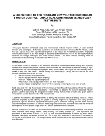
CHAPTER 2 Concepts and Definitions For Arc Flash Risk AssessmentCauses of Electric ArcsArcs can be initiated by the following: Glow to arc discharge:-- Dust and impurities: Dust and impurities on insulating surfaces can providea path for current, allowing it to flashover and create arc discharge across thesurface. This can develop into greater arcs. The fumes or vapor of chemicalscan reduce the breakdown voltage of air and cause arc flash.-- Corrosion: Corrosion of equipment parts can provide impurities on insulatingsurfaces. Corrosion also weakens the contact between conductor terminals,increasing the contact resistance through oxidation or other corrosivecontamination. Heat is generated on the contacts and sparks may beproduced. This can lead to arcing faults with nearby exposed conductors of adifferent phase or ground. Condensation of vapor and dripping water can cause tracking on the surface ofinsulating materials. This can create a flashover to ground and potential escalationto phase-to-phase arcing.1 Spark discharge:-- Accidental touching: Accidental contact with live exposed parts can initiatearc faults.-- Dropping tools: Tools dropped accidentally can cause a momentary shortcircuit, producing sparks and initiating arcs. Over-voltages across narrow gaps: When the air gap between conductors ofdifferent phases is very narrow (due to poor workmanship or damage of theinsulating materials), arcs may strike across during over-voltages. Failure of the insulating materials.Electric arcs are also caused by the following: Improperly designed or utilized equipment. Improper work procedures.4
Practical Solution Guide to Arc Flash HazardsFigure 2.1: (a) Arc Blast in Box;2 (b) Arcing Fault in an Electrical Panel BoardThe Nature of Electrical Arcs Electric arcs produce some of the highest temperatures known to occur on earth—up to 35,000 degrees Fahrenheit.3 This is four times the surface temperature of thesun. The intense heat from an arc causes the sudden expansion of air. This results in ablast with very strong air pressure (lightning is a natural arc). All known materials are vaporized at this temperature. When materials vaporizethey expand in volume (copper— 67,000 times, water—1,670 times4). The airblast can spread molten metal to great distances with force. For a low voltage system (480/277 V), a 3 to 4-inch arc can become “stabilized” andpersist for an extended period of time. The energy released is a function of system voltage, fault current magnitude, andfault duration. Arcs in enclosures, such as in a motor control center (MCC) or switchgear, magnifythe blast and energy transmitted as the blast is forced to the open side of theenclosure and towards the worker.5
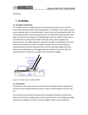
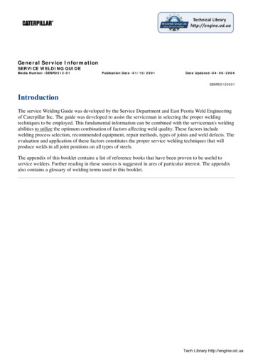
CHAPTER 2 Concepts and Definitions For Arc Flash Risk AssessmentHazards of Arcing FaultsFigure 2.2: (a) Hand Burned by Arc Flash;5 (b) Clothed Areas Can Be Burned More SeverelyThan Exposed SkinSome of the hazards of arcing faults are: Heat: Fatal burns can occur when the victim is several feet from the arc. Seriousburns are common at a distance of 10 feet.6 Staged tests have shown temperaturesgreater than 437 F on the neck area and hands for a person standing close to anarc blast.7 Objects: Arcs spray droplets of molten metal at high-speed pressure. Blast shrapnelcan penetrate the body. Pressure: Blast pressure waves have thrown workers across rooms and knockedthem off ladders.8 Pressure on the chest can be higher than 2000 lbs/ sq. ft. Clothing can be ignited several feet away. Clothed areas can be burned moreseverely than exposed skin. Hearing loss from the sound blast. The sound can have a magnitude as high as140 dB at a distance of 2 feet from the arc.9Probability of SurvivalInjuries due to arc flash are known to be very severe. According to statistics from theAmerican Burn Association, the probability of survival decreases with the increasing ageof the arc flash burn victim.6
Practical Solution Guide to Arc Flash Hazards25% Body Burn8050% Body Burn% Survival10075% Body Burn604020020 - 29.930 - 39.940 - 49.950 - 59.9Age Range, YearsFigure 2.3: Burn Injury Statistics – Probability of Survival (Source: American BurnAssociation, 1991-1993 Study; Revised March 2002)Impacts of Arc FlashTreatment can require years of skin grafting and rehabilitation. The victim may neverreturn to work or retain the same quality of life. Some of the direct costs are: Treatment can exceed 1,000,000/case. Litigation fees. Production loss.Potential Exposure to Arc FlashAlthough it may appear that arc flash incidents are uncommon, statistics show thatthe damage they cause is considerable. Bureau of Labor Statistics data for 1994 show11,153 cases of reported days away from work due to electrical burns, electrocution/electrical shock injuries, fires and explosions.The Census of Fatal Injuries noted 548 employees died from the causes of electricalcurrent exposure, fires, and explosions of 6,588 work related fatalities nationwide.In the US Chemical Industry, 56% of the fatalities that occurred over a 5-year periodwere attributed to burns, fires, and explosions, with many of the ignition sources beingrelated to electrical activity.Capelli-Schellpfeffer, Inc. of Chicago reported that there are 5 to 10 arc flash injuriesper day resulting in hospitalization. Many arc flash accidents and injuries occur that donot require a stay or are not properly documented for national tracking purposes. Thenumber of arc flash accidents is greater than many engineers realize since most arc flash7
CHAPTER 2 Concepts and Definitions For Arc Flash Risk Assessmentaccidents do not make the daily news.IEEE Std 1584, IEEE Guide for Performing Arc Flash Hazard Calculations, provides 49 arcflash injury case histories in Annex C. A brief description is provided for each case onincident setting, electric system, equipment, activity of worker, event, apparel worn bythe worker, and the outcome of the incident. Readers are encouraged to read thesecase histories to gain insights on various conditions leading to such incidents.The exposure to arc flash depends on the following: Number of times the workers work on exposed live equipment. Complexity of the task performed, the need to use force, the available space andsafety margins, reach, etc. Training, skills, mental and physical agility, coordination with helper. Tools used. Condition of equipment. Maintenance conditions of the equipment.Developments in Addressing Arc Flash HazardHistoricall
Practical Solution Guide to Arc Flash Hazards v DISCLAIMER Warning - Disclaimer: The calculation methods listed in the book are based on theoretical equations derived from measured test results. The test results are a function of specific humidity, barometric press