Transcription
General Service InformationSERVICE WELDING GUIDEMedia Number -SENR0512-01Publication Date -01/10/2001Date Updated -04/06/2004SENR05120001The service Welding Guide was developed by the Service Department and East Peoria Weld Engineeringof Caterpillar Inc. The guide was developed to assist the serviceman in selecting the proper weldingtechniques to be employed. This fundamental information can be combined with the serviceman's weldingabilities to utilize the optimum combination of factors affecting weld quality. These factors includewelding process selection, recommended equipment, repair methods, types of joints and weld defects. Theevaluation and application of these factors constitutes the proper service welding techniques that willproduce welds in all joint positions on all types of steels.The appendix of this booklet contains a list of reference books that have been proven to be useful toservice welders. Further reading in these sources is suggested in ares of particular interest. The appendixalso contains a glossary of welding terms used in this booklet.Tech Library http://engine.od.ua
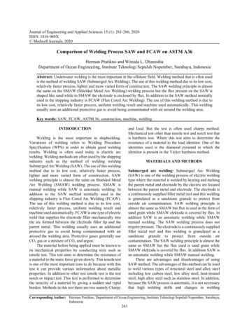
General Service InformationSERVICE WELDING GUIDEMedia Number -SENR0512-01Publication Date -01/10/2001Date Updated -04/06/2004SENR05120002* Keep equipment and work area clean, dry and neat. Put tools away when you are through usingthem.* Be sure work area has adequate ventilation.* Always wear protective gloves and aprons, safety shoes and heavy cotton clothing. Keep collarsand shirt cuffs buttoned. Turn trouser cuffs down. Be sure trouser legs extend below shoe tops.* Wear a welding helmet or eye shield with proper filter plates when welding or cutting. Use a No. 4or No. 5 filter for torch brazing, flame cutting and gas welding. Use a No. 10 or No. 12 filter for arcwelding.* Keep a CO2 or dry powder fire extinguisher within reach-especially when flame cutting orwelding on or near tractors, engines, etc.* Remove all flammable materials, volatile liquids and explosive gases from the welding area orshield them adequately.* Do not weld or cut on containers such as drums, barrels and tanks until you know there is nodanger of fire or explosion from their contents.* Always drill a relief hole in a closed compartment, such as a front idler or track roller frame boxsection, before welding or cutting on it. If this is not done, any moisture inside the compartment canvaporize, causing an extremely high pressure inside the compartment which may lead to anexplosion.* Never strike an arc on a cylinder of compressed gas or on any part of a track adjustingmechanism.* Be sure welding cables, electrode holders and clamps are in good repair and properly insulated.* Support large machine components such as scraper bowls and aprons, bulldozer blade, etc. solidlybefore working under them.* Fasten oxygen an acetylene hoses cylinders securely in the vertical position before using. Observeall safety rules for handling compressed gas cylinders.* Keep oxygen and acetylene hoses from being cut or burned. Inspect oxygen and acetylene hosesperiodically for leaks and worn places. Check all connections for leaks before igniting flame. Do notuse oil on oxygen fittings.* Provide mechanical air movement over coated or painted surfaces being welded to dispel anytoxic fumes that may be produced.Pneumatic Vibrator for slag removalTech Library http://engine.od.ua
* Either chisel or needle typeGrinder, pneumatic or electric* 7 inch or 4 inch diameter - 36 grit and/or 24 grit* Both cup grinder and disc grinder* Cat part #9U-6241 Electric* Cat part #1U-5946 PneumaticElectric Rod Oven for electrode storage if using shielded metal arc* A practical approach is to use an airtight container with at least a 100 watt light bulb permanentlyturned on.* An old refrigerator with sealing door is perfect* Refer to Publications section for purchasing information.Liquid penetrant kit for surface crack detection on ferrous and non-ferrous metals* Cat part #4C-4763 aerosol* Cat part #9U-6335 non aerosolArc-Air for removing defective welds* 3/8 inch and/or 1/4 inch carbon round or semi-round electrodes* Use dry air supply, no lubrication presentOxyacetylene outfit with cutting and heating heads* Cat part #1U-6469 heavy duty Oxy-acetyleneTempilstick crayons for determining temperature of metal* Refer to publications section for purchasing informationLeather weld clothing for operator* Cat part #1U-6583 Leather Gloves* Cat part #1U-6579-80 Leather Coat* Apron or chapsCeramic Weld Backing Material* Cat part #1U-7767 Grooved* Cat part #1U-7768 Round* Cat part #1U-7769 TriangleIf Stick Electrode (SMAW) Shielded Metal Arc Welding* 400 to 600 Amp DC power source is recommended* E7018 electrodeTech Library http://engine.od.ua
If Semi-Automatic (FCAW) Flux Cored Arc Welding* 400 to 450 amp power source is recommended* Shielding gas 75% argon 25% CO2* E71T-1 flux cored wire Cat part #9U-6652If Semi-Automatic (GMAW) Gas Metal Arc Welding* 400 to 450 amp power source is recommended* Shielding gas 75% argon 25% CO2 first choice, and straight CO2 second choice* (AWS) ER70S-3 solid wire Cat part #1U-5368Considerations when using (GMAW) Gas Metal Arc WeldingBase metal cleanliness is more critical when using GMAW than when using SMAW. The fluxingcompounds present in SMAW cleanse the molten weld deposit of oxides and gas forming compounds.Such fluxing slags are not present in GMAW.GMAW is a gas shielded welding process and porosity may occur if too much or too little gas shieldingflow is used. The gas shield can also be blown away by air movement, or by fans running in the weldingarea. The welder must not have too much or too little distance from the welding gun to the piece beingwelded. These are variables to consider when deciding whether to use GMAW or SMAW.Tech Library http://engine.od.ua
General Service InformationSERVICE WELDING GUIDEMedia Number -SENR0512-01Publication Date -01/10/2001Date Updated -04/06/2004SENR05120003DefinitionShielded Metal Arc Welding is an arc welding process wherein coalescence is produced by heating with anelectric arc between a covered metal electrode and the work. Shielding is obtained from decomposition ofthe electrode covering. Pressure is not used and filler metal is obtained from the electrode.Slang Names1. Stick/manual metal arc.Process Principles1. Heat source - heat of the arc.2. Shielding gas - slag formed by the decomposition of the flux.3. Filler metal - comes from core wire.4. Flux - contains deoxidizers/slag formed/ionizing elements to stabilize the arc/iron powder forhigher deposition.Figure 1Methods of Application1. Manual - most widely used - approximately 90%2. Semiautomatic - not used3. Machine4. Automatic - gravity/massive/firecrackerTech Library http://engine.od.ua
Welding CircuitFigure 2Welding Current types1. A.C.2. D.C.E.N. (straight) polarity.3. D.C.E.P. (reverse) polarity.Power Source Types and Characteristics1. Generator (DC)2. Transformer (AC)3. Rectifier (DC)4. Transformer Rectifier (AC/DC)5. Alternators (AC)Other Electrical Requirements1. Multiple OperatorsAdditional Equipment Necessary1. Helmet/gloves/leathers2. Chipping hammer/wire brush3. Grinder for repairThe manner in which equipment is set up in preparation for welding is an important consideration, bothfrom the safety standpoint and for the speed and ease with which the weld can be made.Welding should be done in a specially prepared welding area if at all possible. It is usually quicker andeasier and always safer and more convenient to carry the work to the welder rather than carry the welderto the work. If welding must be done in places other than the regular welding areas, extra attention shouldTech Library http://engine.od.ua
be given to safety precautions, and other workmen in the area should be notified that welding will begoing on.Adequate ventilation and lighting and a source of sufficient power must be provided. The weldingmachine should be located close enough to the work to assure free and easy manipulation of the electrodeholder and cable. Cable connections must be made soundly and the ground cable clamp must be attachedsecurely to the work to assure an uninterrupted flow of current. The ground clamp should always beplaced on the piece being welded; current must never be allowed to flow through bearings, hydrauliccylinders or other precision surfaces. If this occurs, minute pits will form at the points of contact andcause excessive wear.Whenever possible, the work should be positioned so the face of the weld being made and the axis of theweld will be within 10 of horizontal. In this position, higher amperages and deposition rates can be used,the puddle of molten metal is easier to control, and the welder is in a more comfortable position. Inaddition, more welding skill is generally required for welding in positions other than flat and horizontal.An arc is struck by momentarily touching the work with the electrode. When the arc is struck, there is atendency for the electrode to stick to the work because of the sudden rush of current caused by the shortcircuiting of the welding machine. To avoid this sticking or freezing of the electrode, a motion similar tothat used to strike a match should be employed (Figure 3). After the arc is struck, a slightly longer thannormal arc should be held until the parent metal is heated to the melting point and the proper size puddleof molten metal is formed. When it is necessary to restrike an arc to continue an uncompleted weld, therecommended procedure is to strike the arc at the forward or cold end of the crater and move theelectrode rearward over the crater and then forward again to continue the weld. This procedure fills thecrater and avoids porosity in the weld and trapping of slag.Figure 3 - Arcs must be struck carefully to keep electrode from sticking.The two primary factors involved in manipulating the arc are the length of the arc and the amperage of thewelding current being used. The arc must be long enough so the diverging arc stream covers the width ofthe puddle and a good gas shield is maintained. An arc that is too long will tend to swing sideways, causingexcessive spattering, and will result in an imperfect gas shield, allowing elements in the air to come intocontact with the molten metal. This gives rise to a very irregular weld bead with poor penetration (Figure4). Too short an arc, on the other hand, will not heat the parent metal sufficiently and may short out andcause the electrode to stick to the work. An arc of the proper length produces a steady transfer of metalfrom the electrode to the puddle with little spatter and tendency for the electrode to stick. An arc lengthapproximately equal to the core diameter of the electrode will usually produce these characteristics.The proper amperage to be used will vary with different welding situations depending on the type ofmaterial being welded, the type and size of electrode, etc. In general the recommendations of theelectrode manufacturer should be followed. Too low a welding current will not generate enough heat tomelt the parent metal sufficiently. This will result in excessive piling up of weld metal and an overlappingTech Library http://engine.od.ua
bead with poor penetration (Figure 4). Too high a current will give rise to excessive spattering, an irregulardeposit of weld metal, and undercutting along edges of the weld (Figure 4).Figure 4 - Arc length and welding current must be controlled for sound welding beads.Deflection of the arc arising from concentrations of the magnetic field set up in the work can be controlledin a number of ways. Place the ground connection at the start of the weld if back blow is a problem; place it at the endof the weld if forward blow is a problem. Weld toward a heavy tack or a weld already made. Hold as short an arc as possible so the force of the arc offsets the arc blow. Reduce the current, reverse the polarity, or switch to AC current.Once a good arc is established and maintained, the electrode must be held and moved properly to assure asound weld through the control of the puddle of molten metal. Primary factors here are electrode angle,travel speed, and weaving of the electrode. Travel speed should be such that a flat or slightly convex beadis deposited. If travel speed is too fast, a small, irregular bead with a concave surface will result. If travelis too slow a heavy convex bead with overlapping edges will result. Generally, travel speed has to bereduced for vertical and overhead welding.The quality of a weld can be affected to a large degree by the angle at which the electrode is held to thework. For normal flat welds, the electrode should be perpendicular to the surface of the joint and inclinedin the direction of travel. The amount of inclination will affect the penetration, with greater inclinationgiving less penetration. Fillet welds require different electrode angles for successive passes, and theposition of the joint will further affect angle requirements. Specific recommendations for individual typesof welds will be made in the following sections.It is often desirable to lay a weld deposit that is wider than can be obtained with a single bead. This isaccomplished by weaving the tip of the electrode back and forth over the joint as the electrode travelsalong the joint. There are many weave patterns used in welding; the important requirements are that themotion is uniform and the weaves are close enough together to assure good fusion at all points in thedeposit. Again, specific recommendations will be made in the following sections.In addition to widening the weld deposit, weaving helps to work impurities to the top of the puddle ofmolten metal and can be used to control contour and undercutting, as well as heat input and temperaturein a joint. Control of heat input and temperature by weaving is especially useful in vertical and overheadwelding. Disadvantages of weaving include the possibility of losing the gas shield and a possible increasein distortion from warping. Low hydrogen electrodes should not be weaved more than two times thediameter of the electrode in order to avoid breaking the gas shield.Certain environmental factors affect the welder's ability to manipulate the electrode and control thepuddle. The welding area should be orderly, well lighted and well ventilated. For welding in close orrestricted quarters, such as inside the draft tube of a scraper, additional illumination and additionalTech Library http://engine.od.ua
ventilation in the form of a small fan located near the work area is desirable. The welding helmet shouldbe kept clean of smoke and weld spatter.All welding should be done from a comfortable position so the welder can hold a steady arc and feed theelectrode into the joint at a constant rate. Both hands should be free to grip the electrode holder and guidethe electrode or steady the work as necessary. If the joint is in a hard-to-reach or awkward location, theelectrode may be bent in such a manner that the proper electrode angle and arc length can be held from amore relaxed position (Figure 5.)Figure 5 - Electrodes can be bent for welding in hard-to-reach locationsWhen the bead is started, a slightly longer than normal arc should be held until a sufficient amount ofparent metal melts to form a puddle of the proper size. Then the arc length is shortened and travel is begun(Figure 6). At the end of the weld, the bead is stopped by shortening the arc and momentarily backing tofill the crater and then whipping the electrode sharply backward to break the arc. If the bead must bestopped along the length of the weld for any reason (to change the electrode, for instance) the electrodeshould be whipped to the side, leaving an unfilled crater in which to begin the bead. It is often useful tocheck for proper electrode selection, arc control and electrode manipulation by welding on a scrap beforewelding the joint. The scrap should be in the same position as the joint.Figure 6 - Control of the arc is important at the start and finish of a joint.Tack welding permits accurate positioning of members without special fixtures or clamping devices andcontrols distortion arising from cooling welds. Tack welds should be made with the same electrode and inthe same manner prescribed for the final weld. All members of a weldment should be tacked togetherbefore any final welds are made. The following procedure is recommended for making tack welds:1. Hold the member in position and make the first tack weld on the end of the member so themember can be repositioned slightly, if necessary (Figure 7). The first tack should be strong enoughto hold the member in position.Figure 7Tech Library http://engine.od.ua
2. Check the alignment with a level or a combination square (Figure 8). Reposition the member ifnecessary.Figure 83. Make a second tack weld in a place that will further restrain the member from being distortedwhen the final welds are made (Figure 9).Figure 94. Recheck alignment.5. Make additional tack welds as required to hold the member in position while the final welds arebeing made (Figure 9).Tack welds must meet all of the requirements for soundness that apply to final welds. Cracked tack weldsmust be gouged out and remade. If a cracked tack weld is not completely removed, it will initiate futurecracking in the final weld.A weld joint is in the flat position when both the axis of the joint and the face of the weld are within 10 ofhorizontal and the welding is performed on the top of the joint (Figure 10). If the axis of the joint is within10 of horizontal but the face is between 10 and 90 from horizontal, the joint is said to be in thehorizontal position (Figure 10).Figure 10 - Flat and Horizontal positions should be used when possible.For normal flat welds, the electrode should be perpendicular to the surface of the joint and tilted slightly inthe direction of travel (Figure 11). For deeper penetration, the electrode should not be tipped in thedirection of travel, but rather it should be held perpendicular to the face of the weld so the heat from thearc is directed down into the joint (Figure 11). The weave pattern is the same as for normal flat joints.Tech Library http://engine.od.ua
For wide gap joints or joints with a poor fit-up, where excessive heat in the joint would cause amelt-through, the electrode should be tilted slightly away from the direction of travel (Figure 11). Thisangle directs the heat of the arc away from the center of the puddle of molten weld metal and allows themetal to cool more rapidly. The wider weave pattern is used because it also helps the molten weld metalcool more rapidly.Figure 11 - Several electrode angles and weave patterns cam be used for flat welding.For horizontal fillet welds, the electrode should be held midway between the horizontal and vertical plates(45 work angle) on the first pass so an equal force from the arc is directed against each surface (Figure12). The second pass should be deposited against the horizontal plate to form a flat ledge on which thethird pass can be laid. The second pass and all subsequent passes that do not contact the vertical plateshould be made with a 20 work angle (Figure 12). The third pass and all subsequent passes that do notcontact the vertical plate should be made with a 60 work angle. On all passes the electrode should betilted in the direction of travel (Figure 13) so it makes a 60 angle with the horizontal plate (30 leadangle).Figure 12 - Different work angles are needed on various passes for horizontal fillet welds.The weave patterns for horizontal fillet welds utilize the force of the arc to wash molten metal up onto thevertical surface. This technique permits accurate forming of the weld deposit without undercutting (Figure13).Figure 13 - A 30 lead angle puts the electrode 60 from horizontalFor horizontal butt welds, the electrode holder should be held somewhat below the joint so the electrode isdirected slightly upward. The electrode again should be tilted in the direction of travel so it has a leadangle of about 10 . The electrode is directed upward so the force of the arc will hold the puddle of weldmetal in position until it freezes. The weave patterns recommended for horizontal fillet welds (Figure 13)should be used for horizontal butt welds, also. This is done so molten metal can be washed up onto theupper surface to prevent undercutting.Tech Library http://engine.od.ua
A weld joint is in the overhead position when the axis of the joint is within 10 of horizontal and thewelding is performed on the lower side of the joint (Figure 14). If the axis of a joint is between 10 and90 from horizontal, the joint is said to be in the vertical position (Figure 14). Even thorough a jointinclined at, for instance, 30 , is closer to the horizontal than vertical, it is classified as a vertical weldbecause the problems encountered are essentially the same as those of a joint that is completely upright.Figure 14 - Vertical and overhead welding is called out-of-position welding.When working in the overhead and vertical positions, the welder must constantly take steps to counteractthe effect of the force of gravity on the puddle of molten metal. The size of the puddle must be limited byreducing welding current, arc length and deposition rate. This keeps molten metal from dropping from theweld or running down over the work. The amount of slag shield must be reduced through proper electrodeselection so the weld metal will freeze more quickly and in the proper location. The electrode must be heldand moved in such a manner that the force of the arc holds the metal in position until it solidifies. All ofthese factors reduce welding speed and make it more difficult to obtain a sound weld.Overhead welding requires the most skill on the part of the welder. For overhead butt joints and overheadfillet welds where the face of the weld is horizontal. The electrode should be held perpendicular to theface and inclined slightly in the direction of travel (Figure 15). For overhead fillets where the face of theweld is other than horizontal, the electrode should be held so most of the heat is directed onto the uppersurface (Figure 15). In each case, a circular or triangular weave pattern should be used to agitate thepuddle to remove slag and impurities. A series of small beads is easier to run than a single large bead;however, thorough cleaning is necessary after each pass because impurities will not float to the surface ofthe puddle with the overhead position.Figure 15 - Overhead butt and fillet joints require considerable skill from the welder.Vertical welds may be made either upward or downward. Heavy joints are usually welded in the upwarddirection, while small joints on thin material should be welded downward. Welding downward requiressomewhat less skill than welding upward. For both upward and downward vertical welding, the electrodeshould be held perpendicular to the face of the weld and inclined downward (electrode holder below arc)regardless of direction of travel.When making a fillet weld in the upward direction, it is advisable to build a ledge or shelf on which to startthe weld (Figure 16). The shelf should be built to the desired width with a series of short passes. When theshelf is the desired size, the first pass of the weld should be made, using a weave pattern consisting of aseries of inverted V's with the highest point of the pattern in the root of the joint (Figure 16). This patternspreads heat evenly to control the size of the puddle and allows impurities and flux to float downhill to thebrim of the puddle. The bead should be small enough so all flux is kept in a molten or semi-molten state.Tech Library http://engine.od.ua
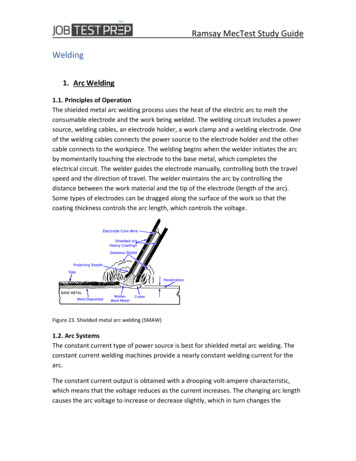
The optional weave pattern (Figure 16) gives a smoother bead, but greater care must be taken becauseslag can easily become entrapped in the center of the pattern.After the first pass has been made, the bead can be enlarged by using a weave pattern consisting ofhorizontal passes with an upward swing at each end. The upward swing is used to tie the weld into thebase metal without undercutting (Figure 16). When low hydrogen electrodes are used, the weave patternshould be kept as narrow as possible to assure a good gas shield around the arc.Figure 16 - The proper weave pattern spreads heat and allows good removal of impurities.Electrodes are usable within a range of amperages. With SMAW welding, the operator has great amountof process control. The operator controls the arc length and uses a manipulating motion to control the arc.Specific welding settings are given in broad ranges. Welders normally listen for a frying or cracklingsound, as well as making a visual inspection to confirm proper setting or make adjustments. Learning theseskills is what makes and experienced welder.E7018 Electrode StorageThese electrodes are to be purchased in hermetically sealed containers. After hermetically sealedcontainers are opened or after electrodes are removed from baking or storage ovens, the electrodeexposure to the atmosphere should not exceed 4 hours, maximum. Electrodes that have been wet shouldnot be used. Electrodes exposed to the atmosphere for periods less than 4 hours may be returned to theholding oven maintained at 250 F (120 C) minimum; after a minimum holding period of 4 hours at 250 Fminimum the electrodes may then be reissued.Electrodes exposed to the atmosphere for more than 4 hours must be baked for at least two hours between500 F (260 C) and 800 F (430 C).All electrodes shall be placed in a suitable oven at a temperature not exceeding one half of the finalbaking temperature for a minimum of one half hour prior to increasing the oven temperature to the finalbaking temperature. Final baking time shall start after the oven reaches final baking temperature.Nominal electrode size reflects the diameter of the metal rod or core of the electrode. The overalldiameter of the electrode with the coating will vary. As the rod diameter increases, the amperagenecessary to produce a good weld will increase. Amperage ranges for difference electrode types can vary,even if the diameters are the same. Recommended amperages for electrodes are sometimes printed on thebox ends. If no recommended settings are found on the packaging, the manufacturer may provideliterature with recommended amperages. If written help cannot be found, consult with an experiencedwelder to select a starting amperage and make adjustments to get the desired weld bead shape andappearance.Low hydrogen type electrodes (5, 6, or 8 as the far-right digit) will absorb moisture from the air if notstored properly. Electrodes are stored in ovens at a minimum temperature of 250 F. Electrode ovens arenot to be used for food warming or storage of any other items.Tech Library http://engine.od.ua
Electrodes left out of the heated storage ovens for longer than two hours must be reconditioned in theoven at least 1 hour at 500 F or 4 hours at 250 F. Porosity of hydrogen-induced cracking will result fromimproper storage and use of the low hydrogen electrodes.Figure 17 - Electrode storage ovenFigure 18 - Label on electrode canFigure 19 - SMAW electrodes showing classification numbersFor electrode numbers with four digits, the two digits on the left denote tensile strength in thousands ofpounds. If the electrode number has five digits, the three digits on the left denote tensile strength. Forboth, the right hand digit indicates the type of coating, and the second digit from the right indicates therecommended positioning for use.Tech Library http://engine.od.ua
Tech Library http://engine.od.ua
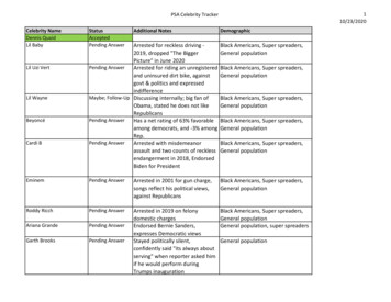
Figure 20Tech Library http://engine.od.ua
General Service InformationSERVICE WELDING GUIDEMedia Number -SENR0512-01Publication Date -01/10/2001Date Updated -04/06/2004SENR05120004The benefits of FCAW are achieved by combining three general features.1. The productivity of continuos wire welding.2. The metallurgical benefits that can be derived from flux.3. A slag that supports and shapes the weld bead.FCAW combines the characteristics of Shielded Metal Arc Welding (SMAW), Gas Metal Arc Welding(GMAW), and Submerged Arc Welding (SAW).Flux Cored Arc Welding has many advantages over the manual SMAW process and provides certainadvantages over the SAW and GMAW processes. In many applications, the FCAW process provides highquality weld metal at lower cost with less effort on the part of the welder than SMAW. These advantagescan be listed as follows.* High quality weld metal deposit.* Excellent weld appearance and smooth, uniform welds.* Excellent contour of horizontal fillet welds.* Many welds weldable over a wide thickness range.* High operating factor, easily mechanized.* High deposition rate, high current density.* Relatively high electrode deposit efficiency.* Economical engineering joint design.* Visible arc, easy to use.* Less precleaning required than GMAW.* Up to 4 times greater deposition rate than SMAW.* Higher tolerance for contaminants that may cause weld cracking.* Resistant to underbead cracking.* FCAW is presently limited to welding ferrous metals and nickel based alloys.* The process produces a slag covering which must be removed.* FCAW electrode wire is more expensive on a weight basis than solid electrode wires, except forTech Library http://engine.od.ua
some high alloys steels.* The equipment is more expensive and complex than that required for SMAW; however, increasedproductivity usually compensates for this.* The wire feeder and power source must be fairly close to the point of welding.* For gas shielded version, the external gas shield may be adversely affected by breezes and drafts.* More smoke and fumes are generated (compared to GMAW and SAW).DefinitionThe Flux-Cored Arc Welding process is a process in which coalescence is produced by heating with an arcbetween a continuous filler metal (consumable)
SERVICE WELDING GUIDE Media Number -SENR0512-01 Publication Date -01/10/2001 Date Updated -04/06/2004 SENR05120003 Definition Shielded Metal Arc Welding is an arc welding process wherein coalescence is produced by heating with an electric arc between a covered metal electrode