Transcription
LED systemsLinear & AreaStrip / Line / SquareDLMFlexHigh FluxDesign-in GuidePerfect mix of designfreedom and high energyefficiencyMay 2019
Published versions12 June - 2013 First version27 June10 February - 201427 March - 201514 April20 May29 July2 August - 201616 February 201711 May06 September24 May 2019 Altered remarks on consequences of using modules at a differentvalue than nominal current or temperature.2Design-in Guide - Philips LED Linear systems LV & HV - May 2019
ContentsIntroduction to this guideHow to Determine which documents contain whatinformation5Warnings and instructions for HV productsWhen using a non-isolated driver, intended for HighVoltage (HV) products6Warnings and instructions for LV productsWhen using an isolated driver, intended for Low Voltage(LV) productsManufacturing phasePhilips Design-in support756777Introduction the Philips LED Linearsystems8Applications and luminaire classification8How to Use LED Linear systems in outdoor luminaires 9Commercial naming of the Philips LED Linear modules9In this design-in guide9Cautions during storage and transportation10When storing this product for a long time (more than one10week)Zhaga11Compose your luminaire with LED Linear12How to Come to your typical LED Linear system12How to Convert to your preferred LED Linear solution 13Electrical design-inReasons why to set your drive currentPhilips Indoor Linear LED driversXitanium driver operating windowInsulation safety indicated by working voltageHow to Select an appropriate driverHow to Configure an LV systemHow to Configure a HV systemLED Line 1 ft SQ and LED Square 2500 lm module –HV/LV HybridHow to Mix different models of LED modulesLED LineLED StripHow to Use different LED module generationsWhole lumen range covered with 3 building blocksHow to Tune the luminaire’s flux and efficacyHow to Set the output current via RsetHow to Program the output currentHow to Wire - general remarksCables and wiresAutomatic wiring by robotElectromagnetic compatibility (EMC)How to Improve EMI performanceMechanical design-inMechanical fixation and creepage forLED Linear modulesHow to. Define cut-out for modules with a back-sideconnectorAlternative fixation methodsMounting Strip for LED Square modulesComplementary partners for fixation 303131333333343636Optical design-inOptics on top of, or near the LED Linear modulesReflector designRequired minimum clearance distance37373939Thermal design-inIntroductionThermal behaviour of indoor linear LED driversTc pointHow to Measure Tc at the Tc pointHow to Tune for anticipated ambient temperature ( C)Influence of thermal resitance of the luminaireHow to Calculate Tc after changing the drive currentCooling via the luminaire housing or cooling plateThermal contactThermal radiation and emissivity coefficientTips for small volume and double chamber conditionsHow to Design for good thermal pact of thermal cycling on product failureLumen maintenance of the Philips LED Linear modulesFuse on Linear LED modules47474750Tips for assembly and installationInserting and removing the cablesBinningElectroStatic Discharge (ESD)How to Meet the ESD requirementServicing and installing alone Philips systems555555Quality, compliance and approvalEnergy efficiency labellingChemical compatibilityCompliance and approval marksIngress Protection – IP rating, humidity andcondensationPhotobiological safetyBlue Light HazardSystem disposalRelevant Standards56565657Contact details and suggested suppliersPhilips LED Linear systemsPhilips PInS ESD supportESD-related material and tool suppliersFurther reading suggestions6060606060AppendixAppendix A: Fluorecent tube reference tableAppendix B: Example wiring schematicsAppendix C: Wiring examples for common -in Guide - Philips LED Linear systems LV & HV - May 201957585859593
4Design-in Guide - Philips LED Linear systems LV & HV - May 2019
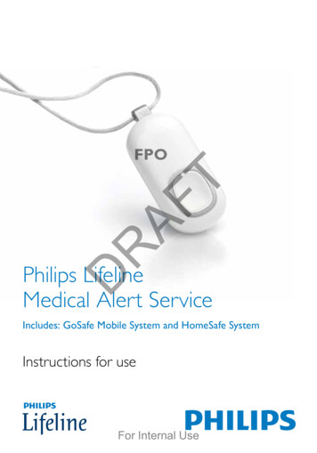
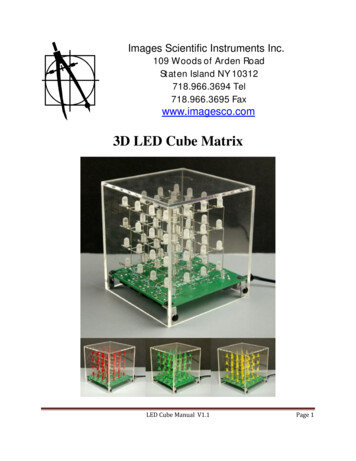
Introduction to this guideThank you for choosing the Philips LED Linear system. Inthis guide you will find the information you need to designthis system into a luminaire.This edition covers the complete Philips LED Linear familyreleased for Europe, including the Low Voltage (LV) andHigh Voltage (HV) version. Also included are the FortimoLED Line High Flux, Fortimo LED Square, which can bewired both as HV and LV system, Fortimo LED Strip andCertaFlux LED Strip. Extensions to the range will beincluded in future updates of this guide. We advise you toconsult our website for the latest up-to-date information.For a full portfolio overview please consult the CommercialLeaflets, to be found in the download section onwww.philips.com/technology.Philips LED Linear system building blocks.Note: LED technology is continuously improving.For the latest updated information, please checkwww.philips.com/technology.How to Determine which documents contain whatinformationIn order to provide information in the best possible andconsistent way, Philips’ philosophy on productdocumentation is the following. Commercial leaflet: product family overview & systemcombinations. Datasheet: product specific specification. Design-In Guide: describes how to design-in the productsinto a system.DatasheetProductinformationCommercial leafletDesign-in GuideThese documents can be found in the download sectionon the OEM website www.philips.com/technology.If you require any further information or support pleaseconsult your local Philips office.Please note that this triangle of information is alsoavailable for the drivers separately.Download sectionof the OEM web.Design-in Guide - Philips LED Linear systems LV & HV - May 20195
Warnings and instructions for HV productsWhen using a non-isolated driver, intended for HighVoltage (HV) productsiWarning: Avoid touching live parts! Avoid touching any bare components on the PCB,e.g. LEDs! Do not use damaged LED modules! Class I luminaires must be connected toprotective earth!Safety warnings and installation instructionsTo be taken into account during design-in andmanufacturing.Design-in phase The general IEC recommendations for luminaire designand legal safety regulations (ENEC, CE, ANSI, etc.) arealso applicable to Philips LED Linear systems. Luminairemanufacturers are advised to conform to theinternational standards for luminaire design (Class I,IEC 60598-Luminaires). Class I luminaires must provide a protective earth! The luminaire must be constructed in such a way that theLED module cannot be touched by an end-user, both inoff state and when live. It is mandatory to design the luminaire in such a way thatit can only be opened with special tools (by a qualifiedperson) in order to prevent touching of live parts. Do not install a reflector near the LED module without aproper earth connection. Do take into account the minimum required creepageand clearance distances. Do not apply mains power to the LED module directly. Connect all electrical components first before switchingon mains. The LED module shall be powered by a LED controlgearIEC/EN 61347-2-13 certified. Avoid possibilities of water or dirt ingress: useappropriate IP-rating of luminaire with regard to specificconditions of application.6Manufacturing phase Do not use damaged or defective LED modules,including damaged connectors or PCB. Do not drop the LED module or let any object fall ontothe LED module because this may damage the PCB orLEDs. If the LED module has been dropped or an objecthas fallen onto the LED module, do not use it, even ifthere are no visible defects or signs of damage. Low voltage (LV) products must not be used incombination with a non-isolated driver. Connect all electrical components first before switchingon mains. The LED module shall be powered by a LED controlgearIEC/EN 61347-2-13 certified.Installation and service for luminaires incorporating thePhilips LED Linear system Do not service the luminaire when the mains voltage isconnected; this includes connecting or disconnecting theLED module cables. The installer must connect the luminaire, if incorporatingthe Philips LED Linear system, to protective earth! Do not use damaged products.For optimal reliability of the LED module we advise not toapply an AC electric strength test to the luminaire as thismight damage the LEDs. It is recommended instead toapply an insulation resistance measurement at 500 VDC(noted as alternative test in IEC/EN 60598-1 annex Q).Philips Design-in supportIs available; please contact your Philips salesrepresentative.Design-in Guide - Philips LED Linear systems LV & HV - May 2019
Warnings and instructions for LV productsWhen using an isolated driver, intended for Low Voltage(LV) productsiWarning: Avoid touching live parts! Avoid touching any bare components on the PCB,e.g. LEDs! Do not use damaged LED modules!Safety warnings and installation instructionsTo be taken into account during design-in andmanufacturing.Design-in phase It is mandatory to use a UL class 2 / IEC compliantSELV driver in combination with the LED LinearLV products. The general IEC and UL recommendations for luminairedesign and legal safety regulations (ENEC, CE, ANSI, etc.)are also applicable to Philips LED Linear systems.Luminaire manufacturers are advised to conform to theinternational standards for luminaire design (e.g. UL1598,IEC 60598-Luminaires). It is advised to construct the luminaire in such a way thatthe LED module cannot be touched by an end-user, bothin off state and when live. Do take into account the minimum required creepageand clearance distances. Do not apply mains power to the LED module directly. Connect all electrical components first before switchingon mains. The LED module shall be powered by a LED controlgearIEC/EN 61347-2-13 certified. Avoid possibilities of water and dust ingress: useappropriate IP-rating of luminaire with regard to specificconditions of application.Manufacturing phase Do not use damaged or defective LED modules,including damaged connectors or PCB. Do not drop the LED module or let any object fall ontothe LED module because this may damage the PCB orLEDs and affect proper functioning of the product. Connect all electrical components first before switchingon mains. The LED module shall be powered by a LED controlgearIEC/EN 61347-2-13 certified.Installation and service for luminaires incorporating thePhilips LED Linear system Do not service the luminaire when the mains voltage isconnected; this includes connecting or disconnecting theLED module cables. Do not use damaged products.For optimal reliability of the LED module we advise not toapply an AC electric strength test to the luminaire as thismight damage the LEDs. It is recommended instead toapply an insulation resistance measurement at 500 VDC(noted as alternative test in IEC/EN 60598-1 annex Q).Philips Design-in supportIs available; please contact your Philips salesrepresentative.Design-in Guide - Philips LED Linear systems LV & HV - May 20197
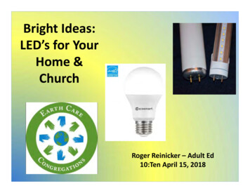
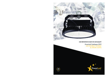
Introduction the Philips LED LinearsystemsPhilips Fortimo LED Strip 650 lm/ftLV (102 mm & 1 ft).Philips Fortimo LED Strip 1100 lm/ft (LV & HV, 1 ft & 2 ft)Philips Fortimo LED Line 1R (1 ft).Philips Fortimo LED Line 2R (2 ft).Philips Fortimo LED Line 3R (1 ft).Applications and luminaire classificationThe Philips LED Linear system is the replacement for linearfluorescent lamps in general lighting. The system features ahigh level of energy efficiency, which surpasses T5 systems,enabling the lowest total cost of ownership (TCO). It offershigh-quality white light with excellent color rendering andcolor consistency. Comes with a multiple year Philipssystem warranty.The LED Linear system consists of a range of modules, theFortimo LED Lines and Strips, and CertaFlux LED Strips onone hand, and the Xitanium and CertaDrive drivers on theother. An overview is presented in the Commercial Leafletof the Linear modules and for the drivers in the downloadsection on www.philips.com/technology. Fortimo LEDLinear comes in a HV version, with best efficiency at lowestprice, and LV version, with ease of design-in. Both rangesfeature a variety of different dimensions, lumen packagesand color temperatures. CertaFlux/CertaDrive systemscome in a HV version only. In this guide you will find thespecific information required to develop a luminaire basedon Philips LED Linear system. Product specificdata can be found in the associated datasheet onwww.philips.com/technology.Both the Philips Fortimo LED Linear HV system andCertaFlux system contain high-voltage solutions thatcomply with European Class I requirements for indoorlighting applications. Other applications or luminaires canbe explored by OEMs as long as this does not create adesign conflict. European luminaire standards, like IEC/EN60598, must be complied with.In this guide you will find the specific information requiredto develop a luminaire based on the Philips LED Linearsystem for both HV and LV products.Philips Fortimo LED Square 2500 lmPhilips Fortimo LED Square 5000 lmPhilips CertaFlux LED Strip gen1 family8Design-in Guide - Philips LED Linear systems LV & HV - May 2019
How to Use LED Linear systems in outdoor luminairesNeither the LED modules nor the indoor Linear LED driverhave an IP classification IP20. Furthermore for outdoorluminaires, compliance to a higher mains surge standard isrequired than the indoor standard LED module is testedagainst. Not complying with the outdoor standard will leadto damaged LEDs. If deciding to use these products in aluminaire for outdoor applications the OEM will beresponsible for ensuring proper IP protection, adequatemains surge protection and approbation of the luminaire.Please consult Philips if you wish to deviate from thedesign rules described in this guide (see last page forcontact details).Commercial naming of the Philips LED Linear modulesThe names of Philips LED Linear are defined as shown inunderneath example. A similar approach holds true forCertaFlux, by replacing Fortimo by CertaFlux.Fortimo LED Line 1 ft 650 lm 840 3R HV2Fortimo : our concept name for efficient, clear and reliablelightingLED: the light source usedLine: linear module (Line, SQ or Strip)1ft: length of LED module650 lm : 650 lumen output840: 8denotes a color rendering index of 80 (CRIdivided by 10) 40 stands for a CCT of 4000 K(CCT divided by 100)3R: indicates the number of LED rows on a LED Line,in this case 3HV: High Voltage: indication of compliance withEuropean class I requirements3: Generation 3In this design-in guideIn this design-in guide you will find all necessary guidelinesto configure the LED Linear system to your needs. The LEDLinear range is designed to enable all types of luminairesin general lighting that were traditionally equipped withlinear fluorescent tubes. The Philips LED Linear range iscapable of truly replacing all those fluorescent luminaires,from a recessed 600x600 office luminaire with 4x14 W T5to a trunking luminaires with 2x80 W T8, from narrowdesign profiles to waterproof luminaires.Design-in Guide - Philips LED Linear systems LV & HV - May 20199
Cautions during storage and transportationWhen storing this product for a long time (more than oneweek) Store in a dark place. Do not expose to directsunlight. For Philips LED Linear modules: do maintain- temperature between -40. 85 C- Relative Humidity (RH) 5.85 %.- For CRI90 HE modules RH 5.70% For LED Line Cover 2ft and 4ft soft-diffuse: maintain.- temperature between -40. 75 C- RH 5.85 %.During transportation and storage for a short timeMaintain temperature below 100 C at normal, noncondensing relative humidity.10Design-in Guide - Philips LED Linear systems LV & HV - May 2019
ZhagaMany LED Linear modules are either Zhaga certified orcompliant. Please check the associated datasheet ofthe LED module you are using for Zhaga details onwww.philips.com/technology.Zhaga is an international organization that is enabling theinterchangeability of LED light sources made by differentmanufacturers. The interface specifications, for theproducts covered in this Design-In Guide designated inBook 7 can now be downloaded from the Zhaga website atwww.zhagastandard.org/specifications.Book 7 covers a variety of rectangular and linear LEDmodules with different dimensions and with separateelectronic control gear that are intended primarily for usein indoor lighting applications. Book 7 modules aretypically mounted directly into a luminaire by means ofscrews.Design-in Guide - Philips LED Linear systems LV & HV - May 201911
Compose your luminaire with LED LinearIn this section you will find all of the product informationneeded to compose a configuration based on the PhilipsLED Linear system.A LED Linear system typically consist of the followingbuilding blocks Philips LED Linear modules. Philips Indoor Linear LED Driver. Standard installation wire (solid core, not offered byPhilips). Optionally a resistor to set the output current (notoffered by Philips). Optionally MultiOne configurator software and hardwareinterface to program TD drivers (to be purchasedseparately from Philips). Optionally Philips controls, like presence detection andlight measuring to allow reduction of energyconsumption.How to Come to your typical LED Linear systemWith below steps we like to provide you with a startingpoint for designing your Philips LED Linear luminaire, eithercoming from a conventional lighting solution or startingfrom scratch.1. Identify your lumen or lumen per length (lm/ft)requirement.2. Determine if you will design for Class I or Class II/SELV.3. Select your preferred LED lay-out (how the LEDs arespread over the module) from available portfolio.4. Select the module type best matching aboverequirements.5. Determine the amount of modules to use in yoursystem.6. Determine the electrical specification of the definedsystem (Voltage [V], current [A] andpower [W]).7. Find your best matching driver (power window,controllability).8. Set or program the drive current on the driver.The upcoming sections will help you in more detail tounderstand how to come to the required answers onabove steps.12Design-in Guide - Philips LED Linear systems LV & HV - May 2019
T8650 and 1000 lm/ftT5 HE 700 lm/ftT5 HO 1000 and 1300 lm/ftWhy replacing fluorescent by smart LED building blocksInstead of replacing hundreds of unique ballastfluorescent tube combinations, as the fluorescent market isused to for decades Philips has chosen in the LEDapproach to use smart building blocks.These are the Philips LED Linear modules in combinationwith the Philips Window drivers – strong in flexibility.LED Linear 650, 1100, 2000 lm/ftRelation between fluorescent lumen and LED Linear lumen.Characteristics of these building blocks are Lengths mimic fluorescent lamps(0.5 ft, 1 ft and 2ft blocks). Driver dimensions mimic conventional ballasts. Various LED lay-outs enabling glare and beam control. Lumen-ranges cover fluorescent lumen packages.By analyzing the mainstream fluorescent lumen packages(amount of lumen per unit length [lm/ft]) three main valuescan be noted as can be seen in the table on the left; 650,1100 and 2000 lm/ft. For reference please see table inAppendix A.However, with the ability to select and set the drive currenton the LED driver you are able to select your light output(lumen) different than the default. This degree of freedomand flexibility we call tuning and will be explained in a latersection.How to Convert to your preferred LED Linear solutionThis section is to help you find your preferred LED Linearsystem solution, starting from your familiar fluorescentsystem. Please find conversion examples in Appendix B, atthe end of this document.Fluorescent light situationLED Linear module consideration1aT5-HE / TL8650 lm/ft1bT5-HO1100 lm/ft1cPL-L2000 lm/ft2aOpen luminaireLV system (ease of design-in)2bClosed luminaireHV system (best TCO)3aBeam shapingNarrow LED lay-out3bGlare & Luminance controlWide LED lay-outConversion help from fluorescent situation to LED Linear system.Design-in Guide - Philips LED Linear systems LV & HV - May 201913
Electrical design-inIn this section you will find all of the electrical design-ininformation needed to design your configuration based onthe Philips LED Linear system.Short introduction to operating LEDsThe LED is a semi-conductor device which, when anelectrical current (Amperes) flows through it, emits light.The current cannot flow without a Voltage over the LED,called the forward Voltage (Vf). Forward Voltage (Vf) is theforce to open the gate, allowing the current to flow throughthe LED. Drive current (Idrive) is transformed into light bythe LED. The amount of light (luminous flux [lm]) isproportional to the amount of current.Reasons why to set your drive currentWith LED as a light source more flexibility in your luminairedesign is enabled with respect to conventional light likefluorescent. We would like to explain to you why youwould want to determine and set your drive current troughthe LEDs.Each LED module needs an electrical current to be able toemit light. In fact, the amount of light – flux [lm] – isproportional to the electrical current flowing through theLEDs.1. For starters, any LED module needs it specific drivecurrent to emit a given amount of light (lm).2. With a generation update, lumen per Watt (lm/W) willimprove, hence the required current to achieve itsluminous flux (lm) will decrease resulting in a lowerrequired drive current.3. Opposite to lamps, LED modules allow composition oflight lines into a system, comprising from one up tomany LED modules in that system. Differentcombinations require different currents and Voltages.4. Changing the drive current through to system (hence it’sLEDs) will enable you to tune to a desired light outputother than the nominal flux specified at the nominaldrive current.14Design-in Guide - Philips LED Linear systems LV & HV - May 2019
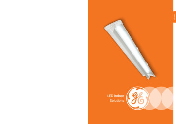
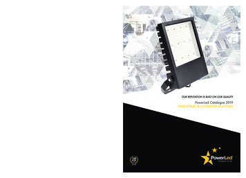
Philips Indoor Linear LED driversFor the drivers, the same documentation philosophy holdsas for the LED modules, meaning that also threedocuments make up the full information set of the drivers.DatasheetFor detailed info, please refer to the Commercial Leaflet ofthe Indoor LED drivers, the Design-In Guide for XitaniumIndoor Linear LED drivers and the associated driver’sdatasheet on t voltage [V]Commercial leafletDesign-in Guide2505200131504100502000.10.20.30.40.5Output current [A]Example of a Driver Operating Window1.2.3.4.5.Required set point for the LED solution.Current can be set to needs within range.Driver adapts to required voltage within range.Driver minimum power limit to guard driverperformance.Driver maximum power limit to guard driverperformance.Note: Power (W) Voltage (V) x Current (A).Note: by means of dimming it is possible to go belowthe minimum value of the specified output current.Xitanium driver operating windowLED technology is rapidly evolving. Using more efficientLEDs in a next generation means the same light output canbe achieved with less power, hence lower drive currents. Atthe same time, LEDs can be driven at different currentslevels based on the application requirement. Typically, LEDdrivers are available in discrete current levels e.g. 350 mA,500 mA or 700 mA. It is often necessary to replacea driver when more efficient LEDs or different LEDmodules become available.One of the key features of the Xitanium LED drivers is theadjustable output current (AOC), offering flexibility,differentiation for the OEM and future-proof luminairedesign. The Xitanium drivers can operate in a so called“operating window”. This power window is defined by themaximum and minimum voltage (V), current (A) and power(W) that the driver can handle. An example of an operatingwindow is shown on the left. The area indicates thepossible current /voltage combinations. The current youselect will depend on the type and manufacturer of theLEDs, the specific LED configuration of the PCB design andthe desired output (lm) per LED.The voltage required is the sum of the LEDs used (total Vfstring). Within the driver window’s range the driver willadapt to the Voltage requirement. Both the operatingwindow and default current setting of every driver can befound in the datasheets in the download section onwww.philips.com/technology.Design-in Guide - Philips LED Linear systems LV & HV - May 201915
Single channel driverCurrently all the Philips Indoor Linear LED drivers are singlechannel drivers. This means for drivers with a double “ ”and “-“ output, that these outputs are in parallel inside thedriver allowing easy connection of parallel LED chains.System configurations with LED LinearAs the default current of the drivers does not necessarilymatch your system drive current requirement, please besure to set and check the current on the driver, e.g. bymeans of current measurement. When configuring thesystem with the Philips driver and Philips LED modules, theselected driver operating point needs to be within thedriver operating window. In case of questions, contact yourlocal Philips representative or the Philips Design-In Team.Setting the driver output currentCertaDrive LED drivers have a fixed output current, nonselectable. Xitanium drivers do have an operating window,allowing to select the output LED drive current. The outputcurrent of these drivers can be set in two ways.1. By connecting a specific resistor value to the driver’sRset input.2. TD driver versions can be programmed via theMultiOne interface in order to set the desired current(www.philips.com/multione).For more information on programming these driversplease check the Design-In Guide of Xitanium IndoorLinear LED drivers in the download section onwww.philips.com/technology.How to determine what value the output current should beset at will be explained in the upcoming sections.Insulation safety indicated by working voltageThe working voltage is the highest voltage that may occuracross any insulation of the module without compromisingthe safety of the module. Any driver with an open load/circuit voltage below the working voltage of the modulecan be safely used in combination with the module.16Design-in Guide - Philips LED Linear systems LV & HV - May 2019
* N ote: when connecting Philips LED modules to thedriver, the type of LED module (LV or HV) determines thisrequirement. Hybrid LED modules (HV/LV in the name)can be used on both type of drivers, indicated inCommercial Leaflet, to be found in the downloadsection of www.philips.com/technology.** Note: Philips LED Linear standard system configurations,driven at nominal current, are stated in the CommercialLeaflet, to be found in the download section ofwww.philips.com/technology. ote: for a HV scenario that allows a 2 chain parallelNsolution, you are likely to find with steps described alower rated driver power (e.g. 75 W for 1 chain versus36 W for 2 chain solution).Power [W] Voltage [V] x Current [A]How to Select an appropriate driverDepending on your requirements several drivers can befound as a solution for you. The following steps can helpselecting the preferred driver.For a full overview of available driver models, please referto the commercial leaflet Xitanium indoor linear LEDdrivers, to be found in the download section ofwww.philips.com/technology, as are the datasheetsassociated with the drivers you intend to use.1. Determine your required drive current (Idrive) andvoltage (Vf).2. Calculate required power via:Pdrive (W) Vf (V) x Idrive (A).3. Determine which type* of driver you do need; Isolated(LV system, Class II/SELV) or Non-isolated (HV system,Class I).Collect the associated datasheets from the website.4. Does required current fit current range of driver?- Idriver minimum Idrive Idriver maximum?5. Does required voltage fit voltage range of driver?- Vdriver minimum Vf Vdriver maximum?6. Does required power fit power range of driver?- Pdriver minimum Pdrive Pdriver maximum?7. Choose your type** of dimming (TD/Dali, 1-10V ornon-dimmable).Design-in Guide - Philips LED Linear systems LV & HV - May 201917
INOUTINOUT---LV LED moduleLV LED moduleHow to Configure an LV systemLV systems typically use LV LED modules or Hybrid LEDmodules suitable for LV usage, connected to an isolateddriver. LV products make a parallel system; adding a LEDmodule requires a higher current.1. Determine the operating current for the desired flux perLED module, using the datasheet. Make sure theoperating current does not exceed the specified valuefor lifetime.2. Drive current from the driver is the sum of the currentrequired per LED module.3. Check whether the resulting total current is within thedriver’s current range. If the current is too low, you candecide to select a driver with a lower output power. Ifthe current is too high for the selected driver, a driverwith a higher output power may provide a solution.4. Connecting too many LV LED modules in a single chainmay lead to flux imbalance. Check the advisedmaximum number of LED modules per chain in theassociated LED module datasheet. If the number of LEDmodules in your system exceeds the specified maximumvalue it is advised to create a second chain.-Schematic representation of the wiring of 2 connected LV LEDmodules in an LV system, not needing a Return-End cableIdrive Inom [A] x # modulesRequired drive current equals nominal current ofone LED module times number of LED modules.Vdrive Vf [V]Required drive voltage equals forward voltage ofone LED module.Note: That the number of LED modules per chain does nothave to be the same for all chains, since all LED modulesare electrically connected in parallel.Note: For your convenience isolated drivers (LV system)comprise a duplicate – parallel
also applicable to Philips LED Linear systems. Luminaire manufacturers are advised to conform to the international standards for luminaire design (Class I, IEC 60598-Luminaires). Class I luminaires must provide a protective earth! The luminaire must be constructed in such a way that