Transcription
EZ-SCREEN Safety Light Screen Original Instruction ManualFeatures An optoelectronic safeguarding device Standard and cascadeable models available C ompact package for smaller production machines,robust for large power presses Creates a screen of synchronized, modulated infraredsensing beams. Choose from two resolutions, sized in150 mm (6″) increments: 14 mm (0.55″) resolution models with defined areasfrom 150 mm to 1.8 m (6″ to 71″) 30 mm (1.18″) resolution models with defined areasfrom 150 mm to 2.4 m (6″ to 94.5″) O ptional remote Test input terminals for simulating a“blocked” condition (available on some emitter models) E asily configured Reduced Resolution (FloatingBlanking) T hree-digit display provides diagnostic information andindicates number of beams blockedC Zone indicators identify blocked beams FMEA tested to ensure control reliability R eceiver LEDs provide system status and emitter/receiver alignment indications H ighly immune to EMI, RFI, ambient light, weld flash,and strobe light Two-piece design with External Device Monitoring Aux. output option to monitor the state of the OSSDs V ibration-tolerant, factory burned-in emitter and receivercircuitry for toughness and dependability U p to four pairs of emitters and receivers of differentlengths can be cascaded (SLSC. models)RUSNIPF(7)UL1998, UL61496Section ContentsSection 1 Introduction . . . . . . . . . . . . . . . . . . . . . . . . . . . . . . Page 1Section 2 System Components and Specifications . . . . . . . . Page 6Section 3 Installation and Alignment. . . . . . . . . . . . . . . . . . . Page 21Section 4 System Operation. . . . . . . . . . . . . . . . . . . . . . . . . Page 41Section 5 Troubleshooting and Maintenance . . . . . . . . . . . . Page 46Section 6 Checkout Procedures . . . . . . . . . . . . . . . . . . . . . . Page 51Section 7 Cascadeable EZ-SCREEN . . . . . . . . . . . . . . . . . . Page 53 Safety PLC input compatible (per OSSD specifications)Printed in USAJul 2014P/N 112852 Rev. I
Table of ContentsEZ-SCREENInstruction Manual1. System Overview . . . . . . . . . . . . . . . . . . . . . . . . . . . . . . . . . . . . page 11.11.21.31.4Introduction . . . . . . . . . . . . . . . . . . . . . . . . . . . . . . . . . . . . . . . . . . . .Applications and Limitations . . . . . . . . . . . . . . . . . . . . . . . . . . . . . . .Control Reliability: Redundancy and Self-Checking . . . . . . . . . . . . .Operating Features . . . . . . . . . . . . . . . . . . . . . . . . . . . . . . . . . . . . .12232. System Components and Specifications . . . . . . . . . . . . . . . . Page 62.12.22.32.42.52.62.7Emitter and Receiver Models – 14 mm . . . . . . . . . . . . . . . . . . . . . . . 7Emitter and Receiver Models – 30 mm . . . . . . . . . . . . . . . . . . . . . . . 8Cables . . . . . . . . . . . . . . . . . . . . . . . . . . . . . . . . . . . . . . . . . . . . . . . . 9Accessories . . . . . . . . . . . . . . . . . . . . . . . . . . . . . . . . . . . . . . . . . . . 10Replacement Parts . . . . . . . . . . . . . . . . . . . . . . . . . . . . . . . . . . . . . . 16Literature . . . . . . . . . . . . . . . . . . . . . . . . . . . . . . . . . . . . . . . . . . . . . 16Specifications . . . . . . . . . . . . . . . . . . . . . . . . . . . . . . . . . . . . . . . . . . 173. Installation and Alignment . . . . . . . . . . . . . . . . . . . . . . . . . . . Page 213.1 Mechanical Installation Considerations . . . . . . . . . . . . . . . . . . . . . .3.2 Mechanical Mounting Procedure . . . . . . . . . . . . . . . . . . . . . . . . . . .3.3 Initial Electrical Connections . . . . . . . . . . . . . . . . . . . . . . . . . . . . . .3.4 Light Screen Initial Checkout . . . . . . . . . . . . . . . . . . . . . . . . . . . . . .3.5 Electrical Interface to the Guarded Machine (PermanentHookup) . . . . . . . . . . . . . . . . . . . . . . . . . . . . . . . . . . . . . . . . . .3.6 Preparing for System Operation . . . . . . . . . . . . . . . . . . . . . . . . . . . .3.7 Sensor “Swapability” and the Optional Emitter Hookup . . . . . . . . . .212829303438384. System Operation . . . . . . . . . . . . . . . . . . . . . . . . . . . . . . . . . . . Page 414.14.24.34.44.54.6Security Protocol . . . . . . . . . . . . . . . . . . . . . . . . . . . . . . . . . . . . . . .System Configuration Settings . . . . . . . . . . . . . . . . . . . . . . . . . . . . .Reset Procedures . . . . . . . . . . . . . . . . . . . . . . . . . . . . . . . . . . . . . . .Status Indicators . . . . . . . . . . . . . . . . . . . . . . . . . . . . . . . . . . . . . . . .Normal Operation . . . . . . . . . . . . . . . . . . . . . . . . . . . . . . . . . . . . . . .Periodic Checkout Requirements . . . . . . . . . . . . . . . . . . . . . . . . . . .4141424346465. Troubleshooting and Maintenance . . . . . . . . . . . . . . . . . . . . Page 475.15.25.35.4Troubleshooting Lockout Conditions . . . . . . . . . . . . . . . . . . . . . . . .Test Mode . . . . . . . . . . . . . . . . . . . . . . . . . . . . . . . . . . . . . . . . . . . . .Electrical and Optical Noise . . . . . . . . . . . . . . . . . . . . . . . . . . . . . . .Servicing and Maintenance . . . . . . . . . . . . . . . . . . . . . . . . . . . . . . .475051516. Checkout Procedures . . . . . . . . . . . . . . . . . . . . . . . . . . . . . . . Page 526.16.26.36.4Schedule of Checkouts . . . . . . . . . . . . . . . . . . . . . . . . . . . . . . . . . .Commissioning Checkout . . . . . . . . . . . . . . . . . . . . . . . . . . . . . . . . .Shift/Daily Checkout . . . . . . . . . . . . . . . . . . . . . . . . . . . . . . . . . . . . .Semi-Annual (Six-Month) Checkout . . . . . . . . . . . . . . . . . . . . . . . . .525253537. Cascadeable EZ-SCREEN . . . . . . . . . . . . . . . . . . . . . . . . . . . . Page 547.17.27.37.47.57.67.77.87.9Overview of Cascading . . . . . . . . . . . . . . . . . . . . . . . . . . . . . . . . . .Cascadeable Emitter and Receiver Models – 14 mm . . . . . . . . . . .Cascadeable Emitter and Receiver Models – 30 mm . . . . . . . . . . .Determining Interconnect Cable Lengths . . . . . . . . . . . . . . . . . . . . .Response Time for Cascaded Light Screens . . . . . . . . . . . . . . . . . .Cascaded Sensor Configuration Settings . . . . . . . . . . . . . . . . . . . .Programming for Cascaded Operation . . . . . . . . . . . . . . . . . . . . . .E-Stop Buttons and Rope/Cable Pulls . . . . . . . . . . . . . . . . . . . . . . .Positive-Opening Safety Interlock Switches . . . . . . . . . . . . . . . . . . .545556575961616263Glossary of Terms . . . . . . . . . . . . . . . . . . . . . . . . . . . . . . . . . . . . . . Page 65Safety Standards and Regulations . . . . . . . . . . . . . . . Inside Back CoverImportant .read this page before proceeding!In the United States, the functions that EZ-SCREEN is intendedto perform are regulated by the Occupational Safety and HealthAdministration (OSHA). Outside of the United States, these functionsare regulated by other agencies, organizations, and governments.Whether or not any particular EZ-SCREEN installation meets allapplicable requirements depends upon factors that are beyond thecontrol of Banner Engineering Corp. These factors include the detailsof how the EZ-SCREEN is applied, installed, wired, operated, andmaintained. It is the responsibility of the purchaser and userto apply this EZ-SCREEN System in full compliance with allrelevant applicable regulations and standards.EZ-SCREEN can guard against accidents only when it is properlyinstalled and integrated into the machine, properly operated, andproperly maintained. Banner Engineering Corp. has attemptedto provide complete application, installation, operation, andmaintenance instructions. In addition, please direct any questionsregarding application or use of EZ-SCREEN to the factoryapplications department at the telephone number or addressesshown on the back cover.In addition to OSHA regulations, several other organizationsprovide information about the use of safeguarding devices. Referto the American National Standards Institute (ANSI), the RoboticsIndustries Association (RIA), the Association for ManufacturingTechnology (AMT), and others (see below). Banner EngineeringCorp. makes no claim regarding a specific recommendation ofany organization, the accuracy or effectiveness of any informationprovided, or the appropriateness of the provided information for aspecific application.The user has the responsibility to ensure that all local, state,and national laws, rules, codes, and regulations relating to theuse of this safeguarding system in any particular applicationare satisfied. Extreme care is urged to ensure that all legalrequirements have been met and that all installation andmaintenance instructions contained in this manual are followed.U.S. Standards Applicable to Use of EZ-SCREENOSHA 29CFR1910 Occupational Safety and HealthStandardsANSI B11 Standards Safeguarding of Machine ToolsANSI/RIA R15.06 Safety Requirements for Robot SystemsNFPA 79 Electrical Standard for Industrial MachinerySee inside back cover for information pertaining toap pli ca ble U.S., European and International stan dards,and where to acquire copies.Banner Engineering Corp. Minneapolis, U.S.A.www.bannerengineering.com Tel: 763.544.3164
EZ-SCREENInstruction ManualOverviewOverview1. System Overview1.1 IntroductionThe Banner EZ-SCREEN provides a redundant, microprocessorcontrolled, opposed-mode optoelectronic “curtain of light,” or “safetylight screen.” It typically is used for point-of-operation safeguarding,and is suited to safeguard a variety of machinery.EZ-SCREEN is extensively FMEA (Failure Mode and EffectsAnalysis) tested to establish an extremely high degree of confidencethat when properly installed, no system component will (even if itshould fail) cause a failure to danger.In typical operation, if any part of an operator’s body (or any opaqueobject) of more than a pre-determined cross section is detected, theOSSD solid-state safety outputs will turn off. These safety outputsare connected to the guarded machine’s Final Switching Devices(FSDs) that control the primary control elements (MPCEs), whichimmediately stop the motion of the guarded machine.Functions such as Trip/Latch select, Display Invert, Cascading,Fixed Blanking, Reduced Resolution (Floating Blanking), Scan Codeselect, and External Device Monitoring are described in Section 1.4.All models require a supply voltage of 24V dc 15%. See Section2.4 for interfacing solutions.Both emitter and receiver feature 7-segment Diagnostic Displaysand individual LEDs to provide continuous indication of theEZ-SCREEN’s operating status, configuration and error conditions.See Section 1.4.7 for more information.This manual contains numerous WARNING and CAUTIONstatements. Warnings refer to situations that could lead to significantor serious personal injury or death. Cautions refer to situationsthat could lead to slight personal injury or potential damage toequipment.The OSSD (Output Signal Switching Device) safety outputs arecapable of performing a “handshake” communication with theMuteable Safety Stop Interface (MSSI) or Universal Safety StopInterface (USSI) found on other Banner Engineering safety products.Banner EZ-SCREEN is a two-piece (“two-box”) system – comprisingan emitter and a receiver, but no external controller. The ExternalDevice Monitoring (EDM) function ensures the fault detectioncapability required by U.S. Control Reliability and ISO13849-1Categories 3 and 4 without a third box, a controller or a “smart” (i.e.,self-checking) safety module required of systems without EDM.An auxiliary (aux.) output may be used to signal the state of theOSSDs to a process controller; see Section 1.4.3.Emitters have a row of synchronized modulated infrared (invisible)light-emitting diodes (LEDs) in a compact rectangular metal housing.Receivers have a corresponding row of synchronized photodetectors.The dimensions of the light screen created by the emitter andreceiver are called the “defined area”; its width and height aredetermined by the length of the sensor pair and the distancebetween them. The maximum range is dependent on the resolution;range decreases if corner mirrors are used. Emitter and receiverpairs with 14 mm (0.55") resolution have a maximum range of 6m (20'), and pairs with 30 mm (1.18") resolution have a maximumrange of 18 m (60').Figure 1-1. A typical EZ-SCREEN application: weld cellElectrical connections are made through M12 (or Euro-style) quickdisconnects. Some emitter models have a 5-pin connector for powerand the Test function. Other emitters and all receivers have an 8-pinconnector for power, ground, inputs and outputs.Banner Engineering Corp. Minneapolis, U.S.A.www.bannerengineering.com Tel: 763.544.3164P/N 112852P/N 133487Rev. I 1
Overview1.2 Applications and LimitationsThe Banner EZ-SCREEN is intended for point-of-operation machineguarding applications and other safeguarding applications. It is theuser’s responsibility to verify whether the safeguarding is appropriatefor the application and is installed, as instructed by this manual, by aQualified Person.Before installing the EZ-SCREEN, read this manual in itsentirety, paying particular attention to this section and all ofSection 3. The EZ-SCREEN’s ability to perform its safeguardingfunction depends upon the appropriateness of the applicationand upon its proper mechanical and electrical installation andinterfacing to the guarded machine. If all mounting, installation,interfacing, and checkout procedures are not followed properly,the EZ-SCREEN cannot provide the protection for which it wasdesigned.EZ-SCREEN is typically used, but is not limited to, the followingapplications: Small assembly equipment Molding and power presses Automated production equipment Robotic work cells Assembly and packaging machines Lean manufacturing systemsEZ-SCREEN may NOT be used with the following machinery orunsuitable applications: Any machine that cannot be stopped immediately after a stopsignal is issued, such as single-stroke (or “full-revolution”) clutchedmachinery. Any machine with inadequate or inconsistent machine responsetime and stopping performance. Any machine that ejects materials or component parts through thedefined area. In any environment that is likely to adversely affect photoelectricsensing efficiency. For example, corrosive chemicals or fluids orunusually severe levels of smoke or dust, if not controlled, maydegrade sensing efficiency. As a tripping device to initiate or reinitiate machine motion (PSDIapplications), unless the machine and its control system fullycomply with the relevant standard or regulation (see OSHA29CFR1910.217, ANSI/NFPA 79, ANSI B11, ANSI/RIA R15.06, ISO12100, IEC 60204-1, IEC 61496, or other appropriate standard).If an EZ-SCREEN is installed for use as a perimeter guard(i.e., where a pass-through hazard may exist), the dangerousmachine motion can be initiated by normal means only after thesafeguarded area is clear of individuals and the EZ-SCREENhas been manually reset. See Section 3.1.2.EZ-SCREENInstruction ManualWARNING. . . Read this Section Carefully Before Installing the SystemThe user is responsible for satisfying all local, state, and nationallaws, rules, codes, or regulations relating to the installation and useof this control system in any particular application. Take extreme careto meet all legal requirements and follow all installation and maintenanceinstructions contained in this manual.The user has the sole responsibility to ensure that the EZ-SCREENis installed and interfaced to the guarded machine by QualifiedPersons in accordance with this manual and applicable safetyregulations.Carefully read this manual in its entirety, paying particular attention toSection 1.2 and all of Section 3, before installing the System. Failureto follow these instructions could result in serious bodily injury ordeath.WARNING. . . Install EZ-SCREEN Only on Appropriate ApplicationsBanner EZ-SCREEN is for use only on machinery that can be stoppedimmediately after a stop signal is issued at any point in the machine’sstroke or cycle, such as part-revolution clutched machines. Under nocircumstances may EZ-SCREEN be used on full-revolution clutchedmachinery or in unsuitable applications as those listed at left. If there isany doubt about whether or not your machinery is compatible withEZ-SCREEN, contact Banner’s Application Engineers at the factory.1.3 Control Reliability: Redundancy and Self-CheckingRedundancy requires that EZ-SCREEN System circuit componentsbe “backed up” to the extent that, if the failure of a single componentwill prevent effective machine stopping action when needed, thatcomponent must have a redundant counterpart which will performthe same function. The EZ-SCREEN is designed with redundantmicroprocessors.Redundancy must be maintained for as long as the EZ-SCREEN isin operation. Because a redundant system is no longer redundantafter a component has failed, EZ-SCREEN is designed to monitoritself continuously. A component failure detected by or within the selfchecking system causes a “stop” signal to be sent to the guardedmachine and puts the EZ-SCREEN into a Lockout condition.Recovery from this type of Lockout condition requires: replacement of the failed component (to restore redundancy) and the appropriate reset procedure (see Section 1.4.8).The Diagnostic Display is used to diagnose causes of a Lockoutcondition (see Section 5.1).Banner Engineering Corp. Minneapolis, U.S.A.2 P/N 112852133487 Rev. Iwww.bannerengineering.com Tel: 763.544.3164
OverviewOverviewEZ-SCREENInstruction Manual1.4 Operating FeaturesThe Banner EZ-SCREEN models described by this manual featureseveral standard selectable functions: Reduced Resolution (Floating Blanking), Trip or Latch Output, External Device Monitoring (EDM), Auxiliary Output, Scan Code setting, Fixed Blanking, Inverted Display, and Cascading (available on SLSC. models).These functions are configured within the sensors, behind theaccess cover on the front of each sensor and in the sensor wiringconfiguration; see Sections 3 and 4.2 for more information andconfiguration DIP switches.The resolution and the maximum range can be determined by themodel number on the emitter and receiver. See Section 2 for a list ofmodel numbers.1.4.1 Selectable Trip/Latch OutputThe setting for Trip or Latch Output also determines whether theSystem will enter RUN mode automatically or if it will require amanual reset first (see Sections 1.4.8 and 4.2). If the System is setfor Trip Output, other measures must be taken to prevent a passthrough hazard; see Section 3.1.2 and the warning below for moreinformation.If Trip Output is selected, the OSSD outputs will turn ON afterpower is applied, and the receiver passes its internal self-test/synchronization and recognizes that all beams are clear. The TripOutput will also automatically reset after all beams are cleared. IfLatch Output is selected, the EZ-SCREEN requires a manual resetfor the OSSD outputs to turn ON, after power is applied and allbeams are clear (see Section 4.5).WARNING. . . Use of Trip/Latch Output Application of power to the EZ-SCREEN components, theclearing of the defined area, or the reset of a Latch conditionMUST NOT initiate dangerous machine motion. Machine controlcircuitry must be designed so that one or more initiation devicesmust be engaged (i.e., a conscious act) to start the machine – inaddition to the EZ-SCREEN going into RUN mode. Failure to followthese instructions could result in serious bodily injury or death.1.4.2 Emitter QD and Hookup OptionsAn EZ-SCREEN emitter with an 8-pin connector can be connectedto its own power supply or to the receiver cable color-for-color(see Figures 3-19 and 3-20). The color-for-color hookup allows theemitter and receiver positions to be interchanged without rewiring.NOTE: An EZ-SCREEN emitter with 5-pin connector and Testfunction (see Section 1.4.4) is not capable of the color-forcolor hookup.1.4.3 External Device Monitoring (EDM)This feature allows the EZ-SCREEN System to monitor the status ofexternal devices, such as MPCEs. The choices are1- or 2-channel monitoring, or no monitoring. EDM is used whenthe EZ-SCREEN OSSD outputs directly control the MPCEs or otherexternal devices; see Sections 3.5.3 and 4.2 for more information.Auxiliary (Aux.) OutputAn aux. output function is available when the receiver is configuredfor 1-channel EDM (for receivers with date code 0834 or newer).This current sourcing (PNP) solid-state output (75 mA max.) isused for control functions that are not safety-related. A typicaluse is to signal the state of the OSSDs to a programmable logiccontroller (PLC). The aux. output follows the state of the OSSDs.Pin 2 (orange/black) supplies the connection; see Section 3.5.5 andFigure 3-23.1.4.4 Remote Test InputOn 5-pin EZ-SCREEN emitter models (model numbers SLSE.-.Q5;see Tables 2.1 and 2.2), a Test function is provided. A pair of wiresis connected from the emitter (see Section 3.5.6) to an externalswitch, typically a normally open contact, held closed. Opening aswitch connected between these two terminals “turns off” the emitter,simulating an interruption of one or more light beams. This remoteTest input may be useful for EZ-SCREEN System setup and to verifymachine control circuit operation.1.4.5 Scan Code ConfigurationThe emitter and receiver may be configured to one of two ScanCode positions (1 or 2). Scan codes enable a receiver to recognizebeams only from an emitter with the same Scan Code setting. Thishelps minimize the effects of crosstalk between multiple emitter/receiver pairs, and allows multiple pairs to operate in close proximityin certain situations. See Sections 3.1.5 and 3.1.8 for propermounting configurations. The Scan Code is set using the selectionswitch in each sensor’s configuration port; see Section 4.2 for moreinformation. Both the emitter and its corresponding receiver must beset to the identical setting.Banner Engineering Corp. Minneapolis, U.S.A.www.bannerengineering.com Tel: 763.544.3164P/N 112852P/N 133487Rev. I 3
OverviewEZ-SCREENInstruction Manual1.4.6 Reduced Resolution (Floating Blanking)Reduced Resolution increases the minimum diameter of an objectthat the light screen can reliably detect anywhere within its definedarea. Reduced Resolution is generally used to allow one or moreobjects (usually workpiece materials) to move through the definedarea, at any point, without tripping the OSSD safety outputs.Selecting two-beam Reduced Resolution will reduce the overallminimum object sensitivity, which allows multiple objects to movethrough the defined area (see Section 3.4.2). The effect is that everytwo consecutive beams (except for the sync beam) can be blocked,but not cause the OSSDs to turn OFF. This is also called “MultiplePoint Floating Blanking.”Beams ofDefined AreaResolution directly affects the minimum allowable distance betweenthe defined area of a light screen and the nearest hazard point(separation distance, see Section 3.1.1). The green status indicatoron the receiver flashes when Reduced Resolution is enabled. Theignored object size and resultant Reduced Resolution are listed inSection 3.4.2.1.4.7 Status IndicatorsStatus indicators on both the emitter and receiver are clearly visibleon each sensor’s front panel. Emitter:Bi-color red/green Status indicator – shows whether power isapplied, and whether the emitter is in RUN mode, TEST mode, orLockout condition.1-Digit Diagnostic Display – indicates specific error or configurationconditions. Receiver:Bi-color red/green Zone indicators – show status of a group ofbeams:- aligned and clear (green ON), or- blocked and/or misaligned (red ON), or- fixed blanked area (flashing green). ellow Reset indicator – shows System status:Y- RUN mode (ON) or- waiting for a reset (flashing). i-color red/green Status indicator – shows System status:B- Reduced Resolution enabled (flashing green),- outputs are ON or OFF (green ON or red ON), or- the System is in Lockout condition (flashing red).WorkpiecePress BreakDie3 -Digit Diagnostic Display – indicates specific error, configurationconditions, or total number of blocked beams.Figure 1-2. Reduced ResolutionSee Sections 4.4 and 5.1 for more information about specificindicator and Diagnostic Display code ne Indicators(each showsstatus of approx.1/8 of the totalbeams)1-digitDiagnosticDisplayYellow ResetIndicatorStatus Indicator(Red/Green)Status Indicator(Red/Green)Zone 1 Indicator(indicates beam synchronization status)Figure 1-3. EZ-SCREEN emitter and receiver status indicatorsBanner Engineering Corp. Minneapolis, U.S.A.4 P/N 112852133487 Rev. Iwww.bannerengineering.com Tel: 763.544.3164
OverviewOverviewEZ-SCREENInstruction Manual1.4.8 Manual Resets and Lockout ConditionsReset RoutineThe EZ-SCREEN requires a manual reset to clear a Power-UpLockout or Latch condition, and after correcting the cause of aLockout condition. This function is designed to provide a “monitoredmanual reset” (i.e., open-closed-open action), such that a shorted ortied-down button cannot cause a reset. When a key-operated switchis used, this is typically called a key reset.To perform a manual reset, close the normally open switch for atleast 1/4 second, but no longer than 2 seconds, and then re-openthe switch. See Sections 3.1.3 and 4.3 for further information.A Lockout condition will cause the EZ-SCREEN OSSD outputs toturn OFF. A Lockout condition is indicated by a flashing Red Statusindicator and an error number displayed on the Diagnostic Display.Internal Lockout conditions require a manual reset routine to returnthe system to RUN mode after the failure has been corrected and theinput has been correctly cycled. A description of possible lockouts,their causes, and troubleshooting hints are listed in Section 5.Trip Output/Auto ResetWhile the use of a reset switch is recommended, it is not requiredfor receivers configured for Trip Output (automatic reset). Cycling thesupply power (OFF for 2 seconds, then ON) will also clear lockoutsif their cause has been corrected. If a reset switch is not used,leave pin 8 (violet wire) not connected (open) and secure it againstshorting to a source of power or ground.1.4.11 Cascadeable ModelsEmitter and receiver models SLSC.* (see Section 7) are capable ofinterconnecting up to four emitter/receiver pairs – regardless of theresolution, the total number of beams, or the size of the defined area.EZ-SCREEN cascadeable models can also be used individually asstand-alone systems.Special cabling is not required, but the double-ended 22 awgcordsets listed in Section 2.3 are recommended. See Section 7.4 formaximum cable lengths. Pigtail QD models may be used to reducethe number of required cables.Response time is dependent on the number of beams in the lightscreen, and the light screen’s position in the cascade. Maximumsystem response time can be calculated easily for these cascadedsystems, in two ways: Individually for each light screen in the cascade (separationdistance is calculated for each light screen in the cascade), or Based on the worst-case maximum for the entire cascade (all lightscreens in the cascade have the same separation distance).See Section 7.5 for more information.*Models SLSC.-150. not available.1.4.9 Fixed BlankingThe fixed blanking feature allows for a stationary object(s), such astooling, to be ignored while it remains positioned in the defined area.A flashing Green Zone indicator denotes the location of a blankedarea. If the object is moved or removed, the System goes into alockout mode. This ensures that an unexpected hole in the sensingfield is not created.Fixed blanking is easily programmed, simply by positioning theobjects, flipping two DIP switches and resetting the System, asdescribed in Section 3.4.3.1.4.10 Inverted DisplayA push button, located under the access cover, can be used toinvert the display. This is desirable when an emitter and receiverare mounted with the QD connector ends up. A replacement accesscover with an inverted label is included with each emitter andreceiver to accommodate inverted mounting. (See Section 4.4).Banner Engineering Corp. Minneapolis, U.S.A.www.bannerengineering.com Tel: 763.544.3164P/N 112852P/N 133487Rev. I 5
Overview ionsEZ-SCREENInstruction Manual2. Components and SpecificationsAn EZ-SCREEN System includes a compatible emitter and receiver (equal length and resolution; available separately or in pairs), and twocables.
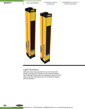
The Banner EZ-SCREEN provides a redundant, microprocessor-controlled, opposed-mode optoelectronic “curtain of light,” or “safety light screen .” It typically is used for point-of-operation safeguarding, and is suited to safeguard a variety of machinery