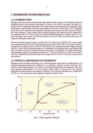
Transcription
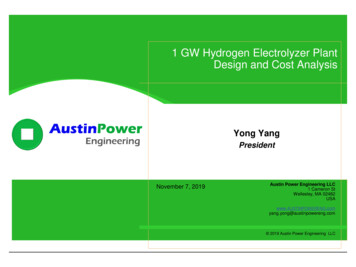
1 GW Hydrogen Electrolyzer PlantDesign and Cost AnalysisYong YangPresidentNovember 7, 2019Austin Power Engineering LLC1 Cameron StWellesley, MA reng.com 2019 Austin Power Engineering LLC
IntroductionOverviewAustin Power Engineering LLC is an independent technology consultingcompany that focuses mainly on bottom-up technical cost modeling.Terminal plateInsulatorCathode pinFanLT CoolantPumpGasketInsulator caseHydrogenElectrolysisSafety ventSpring plateCathode leadHydrogenStorageLT CoolantElectricMotorPurge ValveHumidified halpyWheelPressureRegulatorEjectorAnode canCIDHT CoolantPumpHT/LT RadiatorsHT CoolantTop utionMixerAirSeparatorExhaustSource: Dr. Rajesh Ahluwalia of ANLAnodeCathodeFuel CellBatteryHydrogen & Fuel Cell Manufacturing Cost Modeling200220032004200520062007Arthur D Little / 19Austin Power Engineering2019 YY1
Project ObjectiveWe will analyze a 1 GW (200,000 Nm3/hr / 500 ton H2 per day) hydrogenelectrolysis plant capex.Electrolysis Plant CAPEXTotal Project Cost Stack BOPFactory CostCorporate Factory CostXExpensesResearch and DevelopmentSales and MarketingGeneral & AdministrationWarrantyTaxesFixed Costs Equipment and Plant Depreciation Tooling Amortization Equipment Maintenance Utilities Indirect Labor Cost of capital Overhead Labor BuildingVariable Costs Manufactured Materials Purchased Materials Fabrication Labor Assembly Labor Indirect MaterialsOEM Markup Additional ExpenseSale Price / CapexDirectlaborDirectMaterials* Have done 200 kW, 1MW, 2 MW, 10MW, 50 MW, 100 MW, 250 MW, 500 MWhydrogen electrolysis plant cost analysisfor various clients.2019 YY2
ApproachManufacturing Cost Modeling MethodologyThis approach has been used successfully for estimating the cost of varioustechnologies for commercial clients and the on &Validation Define system valuechain Quote off-shelve partsand materials Select materials Develop processes Assembly bottom-upcost model Develop baseline costs Technology scenarios Sensitivity analysis Economies of Scale Supply chain &manufacturing systemoptimization Life cycle cost analysis Cost model internalverification reviews Discussion withtechnical developers Presentations to projectand industrial partners Audition byindependent e SideCatalyst Layer99%99%100%100%98.5%100%100%98.5%98.5%Nafion MembraneHot 99.9%StackConditioningStack Assembly2.7% Membrane6.3%8.0%Balance of Stack2.4%Seal8.4%PEMFC Plug Hybrid VehicleFull Battery Electric Vehicle98.5%AnodeInk100%70,00098.5%Cathode SideTotal Cost of Owership ( ) Literature research Definition of system andcomponent diagrams Size components Develop bill-ofmaterials (BOM)ManufacturingCost ipolar Plate26.1%Catalyst Layer10,00098.5%PurchasedGDL100%100%03-Year TCO5-Year TCO10-Year TCO15-Year TCOGDL5.1%2019 YY3
ApproachManufacturing Cost Modeling MethodologyCombining performance and cost model will easily generate cost results, evenwhen varying the design inputs.Conceptual DesignProcess SimulationProcess Cost CalcsAir (POX only)99.99% pure H2Compressor with intercoolers 10MaterialNat. GasFuelReformer 9PSACoolingTowerProcess 8H2-rich gas 7HeatWafer Cost ( )WaterColdWaterCatalyticBurnerCO2H2OH2-poor gas 6 5 4 reStorageFlowcntrlrFlowcntrlrFlowcntrlr 2To Vehicle Sp2utteringRFNSpiutteringESpinCoating 0DispenserSite PlansProcess costMaterial costEnergy requirementsEquipment size/ specsSystem layout andequipment requirementsCapital Cost EstimatesProduct Costs80,000NG line inFuel Station PerimeterH2 High PressureCascade StorageSecurity FenceSystem70,000PEMFC Plug Hybrid VehicleFull Battery Electric earInterconnectPaint BrazeontoInterconnectBrazeCNG High PressureCascade Storage SystemAnodeFire DetectorGaseous FuelDispensing IslandsElectrolyteAnodePowder PrepElectrolyteSmall PowderPrepTape CastVacuumPlasmaSprayCathodeCathodeSmall PowderPrepFabricationVentCovered Fueling IslandSlip CastElectrolyzer or SMR,High-PressureCompressorSinter in Air1400CQC urry SpraySlurrySpraySite Plan - Fueling StationProperty of:TIAX LLC1061 De Anza Blvd.Cupertino, CA 95014SIZEDWG BYAStefan UnnaschSCALE1" 8 ftDWG NOSHEETFinish EdgesStack AssemblyREVB0228 - S00225 Jan 2004Sinter in AirNote: Alternative production processes appear in gray to thebottom of actual production processes assumedHydrogen and CNG fueling stationTask 5 CNG/Hydrogen Fueling10 ftBlanking /SlicingTotal Cost of Owership ( )Underground Piping with shared conduit60,00050,00040,00030,00020,00010,00003-Year TCO15-Year TCO10-Year TCO15-Year TCO1 OF 1Minimum set-back distances for hydrogen and/or natural gasstorage (more stringent gas noted if relevant)Walls with minimum fire rating of 2 hours5 ftftWall openings (doors & windows)25 ftftBuilding intake vents50 ftftAdjoining property that can be built on10 ftftPublic sidewalks, parked vehicles15 ftftStreets10 ftftRailroad tracks15 ftftOther flammable gas storage10 ftftSafety equipment, siteprep, land costsHigh and low volumeequipment costsProduct cost (capital,O&M, etc.)2019 YY4
ApproachProject Scope1 GW hydrogen electrolyzer plant boundary limits:CapexGrid connectionElectrolyzer stackPeripheral componentsBalance of plantOptional additional hydrogencompressionAC-DC power supplyOptional hydrogen storageSystem controlFeed water treatmentGas / liquid loopsCompressor (if needed)De-oxygen unitGas dryingCooling systemIncluded in analysisHydrogen OutputProject development30 bargPermittingOxygen limit: 5 ppmMoisture content:Engineering-65 oC dew pointCivil works and installationPiping, fitting, valves,instrumentLand useAssembly, conditioning,testing, packagingSelling, general andadministrative expenses,marginsHighly site and situation-specificIndicative estimated for engineering andproject cost is given separately based ontextbook factors2019 YY5
ApproachCost Reduction OptionsComparing large scale hydrogen electrolysis plant with small hydrogenelectrolyzer, cost reduction mainly comes from the following areas:1.2.Improve stack performance Increase current density Simplify stack structure Reduce precious metal loadingLarge scale production 3.4.5.Process automation, etc.Increase the stack size Current 1 5 MW Future 5 20 MWModular vs Integrated Capex Project cost O&M costSystem BOP optimization Power supply Mechanical compressors if apply H2 gas purificationLow cost region manufacturing2019 YY6
ApproachStack OptionsWe screened major electrolyzer manufacturer’s MW level electrolyzer stacks.AlkalineelectrolyzerPEMelectrolyzerAtm. pressurePressurized NEL A485 2.3 MW McPhy 2 MW ModuleCommercial ThyssenKrupp Asaki Kasei -Atm. pressure SiemensSOECPressurized Hydrogenics 3MW ITM Power 2MW Module NEL/Proton Onsite MWModule Giner EXL 1MW Siemens 1 2 MWChinese ManufacturersPericJingliTianjin Continental NEL/GHWHight temperatureelectrolyzerProtonConductiveSOEC Tubular Planar Potential 10 MW stacksPre-commercial2019 YY7
ApproachStack OptionsThe chosen cell voltages and current densities are based on current technologystatus. The chosen cell voltage (1.75V) largely determines the cell efficiency (85% HHV) This low cell voltage is used to reflect that such large plants will be optimized for efficiency. Assume current atm. pressure alkaline electrolyzer current density is 175 mA/cm2 Assume current PEM electrolyzer current density is 1,500 mA/cm2.Future TechnologyCurrent Technology2019 YY8
ApproachBOP OptionsWe must consider the capex, project cost, as well as O&M cost when wedesign the electrolysis plant project.BOPCapexProject CostO&M CostOutdoor Modular DesignModularDesignIntegratedDesign Integrated BOP Design2019 YY9
Design Scenarios1 GW Hydrogen Electrolysis Plant StackMajor stack specifications MElectrolyzerFuture KPIPEMElectrolyzerCurrent KPICurrent KPIPlant size (MW, DC basis)957960960960Stack size (MW)2.3102.510# of stacks4169638496Cell voltage (V)1.751.751.751.75Current density (A/cm2)0.1750.751.502.50# of cells258258258258Stack voltage (VDC)452452452452Stack Current ual cell area (cm2)34,20834,7044,85211,644Operating Pressure (barg)0.02.063030Stack production volume (GW/year)1111Purity (%)99.9999.9999.9999.99Oxygen limit 5 ppm 5 ppm 5 ppm 5 ppmMoisture content- 65 C dew point- 65 C dew point- 65 C dew point- 65 C dew pointParameterCell active area (cm2)Future KPI2019 YY10
Design Scenarios1 GW Hydrogen Electrolysis Plant BOPMajor BOP components MElectrolyzerFuture KPIPEMElectrolyzerCurrent KPICurrent KPIPower supplyxxxxH2 gas/liquid separatorxxxxO2 gas/liquid separatorxxxxH2 gas lye scrubberxxH2 booster compressorxxDe-oxo unitxxxxTSA dryerxxxxDI water systemxxxxStack cooling systemxxxxH2 gas chiller before boost compressorIncluded in the boostcompressor costH2 gas chiller before TSA dryerIncluded in the deoxounit costIncluded in the boostcompressor costIncluded in the deoxounit costIncluded in the boostcompressor costIncluded in the deoxounit costIncluded in the boostcompressor costIncluded in the deoxounit cost# set of BOPs in system2222ParameterFuture KPI2019 YY11
Current Alkaline: 1 GW Alkaline (2.3 MW stack), 2 sets of BOP, simplified P&IDTCPGas/LiquidSeparatorPTT1Solenoid ValveVents toatmosphereoutside facilityManual ValveO2 VentxTCLH1DrainVesselPower Transformer230KV AC / 66kV ACRectifier452VDC;TCPDry Cooling / Cooling Tower(Lye Cooling)PTFACILITY INTERFACERectifier Transformer x 2866KV ACWaterFiltration Circulation Pump16 stacksGroup 1Non ReturnValveTCTap WaterDI Water TreatmentCirculation PumpLye TankPTT2T3LH2To Lye Tank230 kV3 PhasexPT TCLCoolingWaterOutletH2 Group 25CoolingWaterInletPTTCH2 PortDe-oxoUnitTo Lye TankH2 BufferTank16 stacksCooling TCWaterInletPH2 VentPressure Relieve ValveRegenerationxAdsorption TCTCTCPCoolingWaterOutletLye drogenCompressorNitrogen Set # I BOP for stack group 1-1316 stacksGroup 26Set # 2 BOP for stack group 14-26LEGENDAuxiliary PowerLElectronicLevel Sensor24 VDC PowerSupplyTCPiston PumpPressure TransducerCheck ValveCompressorPower 110 VAC3-WayManual BallValveSolenoid ValveManual ValveControl SystemPressure ReleaseValveProcess FilterPTPPressure TransducerPressure GaugePower 380VAC2019 YY12
Current Alkaline1 GW Plant LayoutAlkaline 2.3MW x 416Total area: 172 m x 450 m 77,400m2Indoor area: 48,880 m2Gas/ liquid separation20meterKOH Scrubber KOH Scrubber7 meterGas/ liquid separationDe-oxoDe-oxoTSA DryerTSA DryerCompressorDI Water10 meter10 meter4 meterIndoor20 meter20 meter100meter10meter150 meterIndoor230KVSubstation42meter40 meterIndoorSystem Control& Offices60 x 30 meter450 meter2019 YY13
Current Alkaline:Stack OverviewAtmospheric pressure alkaline electrolyzer design:Key ParametersDiaphragm Zirfon Perl diaphragm 0.5 mm thicknessAnode Electrode Substrate: 0.3 mm Ni Mesh Coating: NiAl (56/44)wt; 90 µmCathode Electrode Substrate: 0.3 mm Ni MeshFrame / Structure Ring Machined Carbon steel with PTFEcoatingCell gasket EPDM 1 mm thicknessSeparator Plate Ni coated carbon steel 2 mm thicknessUS patent: 9,556,5292019 YY14
Current AlkalineElectrode and Bipolar Plate Current Process AssumptionsAnode, cathode, and bipolar plate fabrication processes:Anode:SS Mesh umPlasmaSprayingHClEtchingCarbon SteelSeparator PlateLaser CuttingMachiningNickelCoatingAssemblyInspectionNi Mesh SheetCathode:Laser CuttingPressStamping2019 YY15
Current AlkalineCell Frame and Membrane DiaphragmDiaphragm and cell frame fabrication processes:PlasmaCutting IIGas/liquid Separator ChamberCarbon SteelPlasmaCutting ameAssemblyFrame:Carbon raneAssemblyCarbon SteelLaser CuttingMembrane Support RingNickelCoatingInspectionPPS FeltMembraneWater JetCuttingMembrane O-ring2019 YY16
Other Stack Scenarios OverviewWe designed the stacks based on patents and public available information,etc.Single Element CellRepeated cell components:Ti wire meshFrame sealAnode Side Cell ShellCell frameAnode Side Current Distribution LayerSintered TifoamTi wire meshAnodePTLDiaphragmMEA gasketCathodeAnodeCathode Side Elastic LayerMembraneO2, Anode sideH2, Cathode sideCathodeCathode Side Current Distribution LayerFrameSealCell frameMEA gasketCathode Side Cell ShellCarbon TiSinteredPaperfoamTi wire meshPTLCell GasketsTi wire meshCell frameCell Pitch 6mmUS patent: US20170088959A1Frame sealUS patent: US 9,556,529Cell Bipolar plateCurrent PEM Scenario:2.5 MW 30 Barg PEM Electrolyzer StackFuture Alkaline Scenario:10 MW Atm. Pressure Alkaline Electrolyzer StackRepeat cell componentsFrame sealFormed Ti PlateCell frameO2PTLSintered Ti foamAnode sideFrame sealMEA gasketAnodeMembraneFrameGasketCell frameFuture PEM Scenario:10 MW 30 Barg PEM Electrolyzer StackCathodeMEA gasketFrame sealPTLCell frameCathode sideH2Sintered Ti foamCarbon PaperFormed Ti PlateFrame sealCell Bipolar plate2019 YY17
BOP ComponentsWe assume there are two sets of BOP systems which make the system easy tomaintain and give the benefit of resiliency.Major BOPComponentsDescriptionsPower supply230KV Substation; N 1 transformerdesignH2 gas/liquid separatorIntegratedO2 gas/liquid separatorIntegratedH2 gas lye scrubberIntegratedH2 booster compressor 20,000 HP x 2De-oxo unitPt on Al2O3 pellets at 108 CoTSA dryerUOP Molesieve pelletsDI water systemElectric conductivity, 1 Siemens/cm forPEM; 5 Siemens/cm for AlkalineStack cooling system 20,000 cooling tonsExample Power Supply DiagramExample De-oxygen & TSA Dryer Diagram2019 YY18
Capex SummaryEstimated 1 GW electrolyzer plant capex fall into the range of between 400/kWand 600/kW. Today 1 2 MW electrolyzers’ capex ranges from 600/kW to 2,000/kW Modelled 1 GW electrolyzers’ capex ranges from 400/kW to 600/kW1Electrolyzer Capex ( /kW)3000250020001500100050020Today 1 2 MW Electrolyzer Capex1 GW electrolyzer Plant Capex1. Made in US or western Europe countries; cell efficiency is about 85%; output H2 gas purity is 99.99% at 30 barg2. Units made in China and sold in China only; as low as 200 300/KW2019 YY19
Total Project Cost DiscussionTotal project cost also includes project “soft” cost which is highly site andsituation specific. Container based 1 2 MW electrolyzers’ project cost is minimum 1 GW electrolyzer plant total project cost ranges from 600/kW to 1,800/kW(additional 50% 200% project “soft” cost) Typical Project “Soft”CostPermitting3000 Building (includingservice facilities)2500 Engineering &supervision Installation Legal expense Contract fee ContingencyTotal Project Cost ( /kW) 200015001000500*0Today 1 2 MW Electrolyzer Total Project Cost1 GW electrolyzer Plant Total Project Cost* Units made in China and sold in China only; as low as 200 300/KW2019 YY20
Thank You!Contact: Yong YangAustin Power Engineering LLC1 Cameron St,Wellesley, MA 02482 1 781-239-9988 1 powereng.comOnline research report store: http://austinpowereng.com/store.php2019 YY21
Power Transformer 230KV AC / 66kV AC YY 16 stacks YY 16 stacks YY 16 stacks P Cooling Water Inlet Cooling Water Outlet Hydrogen Compressor H2 Buffer Tank Set # I BOP for stack group 1-13 Set # 2 BOP for stack group 14-26 Circulation Pump Manual Valve Circulation Pump 2019 YY. 13 Current