Transcription
GTU Paper Analysis (New Syllabus)Power Plant Engineering (2171910)Paper AnalysisMAY - 18NOV-17QuestionsNo.MAY – 17Sr.DEC – 16Chapter 1 – Thermal Power PlantTheory1.Draw general layout of modern thermal power plant.42.Draw a neat layout of thermal power plant and make a list of site selection criteria for the same.4743Chapter 2 – High Pressure BoilerTheory1.State desirable to control the super heat temperature. Explain desuperheater method.32.Explain working of Schmidt-Hartmann boiler with neat sketch.73.Draw a line diagram of a Benson boiler. State the main difficulties experienced in the La Mont boiler and7how it is prevented?4.Discuss FBC. Explain CFBC with neat sketch5.What is sub-critical and super critical boiler?73Chapter 3 – Coal and Ash Handling SystemTheory1.Explain working of Bowl pulverizing mill with neat sketch.Power Plant Engineering (2171910)Department of Mechanical EngineeringDarshan Institute of Engineering & Technology73
GTU Paper Analysis (New Syllabus)2.Explain Unit pulverized coal handling system with neat sketch.43.Discuss requirements of oil burners. With neat sketch explain long flame, turbulent burners and7tangential Burners.4.Enumerate different types of Ash handling system. Explain Pneumatic ash handling system with7advantages and disadvantages.5.Discuss In-plant coal handling system446.Explain the statement:- “Coal handling system is called lifeline of the coal fired power plants”.37.Explain pulverized coal system and state its merits and demerits.7Chapter 4 – Draught SystemsTheory1.Distinguish between force draught and induced draught.32.State the classification of Draught. Derive an expression for maximum discharge through a chimney.3.Advantages of Mechanical draught over Natural draught.4.With usual notations derive an expression of estimation of height of chimney and condition of maximum discharge3743and Prove the following:Maximum discharge through chimney occurs when7𝑇𝑔 𝑇𝑎 2(𝑚𝑎 1) 𝑚𝑎Where Tg and Ta are gas and air temperature respectively and ma is mass of air.Chapter 5 – Steam NozzlesTheoryPower Plant Engineering (2171910)Department of Mechanical EngineeringDarshan Institute of Engineering & Technology
GTU Paper Analysis (New Syllabus)1.Define critical pressure.𝑝22Derive𝑝 (𝑛 1)1𝑛𝑛 1;7where P2 is throat pressure, P1 is inlet pressure and n is the index of isentropic expansion of steam through the7nozzle.2.Derive equation of critical pressure ratio of nozzle and explain its significance. Calculate its value for superheatedsteam.3.Derive the condition and then equation of maximum discharge through the nozzle, also write maximum7discharge for different condition of steam.Examples1.The pressure and temperature of steam entering the nozzle are 12 bar and 200 C and steam leave the nozzle at1 bar. The diameter of the nozzle at throat is 10 mm. Calculate the mass flow rate of steam in a nozzle and which7type of nozzle is required?2.Steam is expanded in nozzle from 15 bar and 350 ºC to 1 bar. Find the throat and exit area if flow rate is 1 kg/sec.7What should be coefficient of velocity if exit velocity is 1150 m/sec?3.Dry saturated steam at a pressure of 8 bar enters a convergent divergent nozzle and leaves it at a pressure of 1.5bar. If the flow is isentropic and the corresponding expansion index is 1.135;7Calculate the ratio of cross-sectional area at exit throat for maximum discharge.Chapter 6 – Steam TurbineTheory1.Explain pressure-velocity compounding of impulse turbine with diagram.Power Plant Engineering (2171910)Department of Mechanical EngineeringDarshan Institute of Engineering & Technology77
GTU Paper Analysis (New Syllabus)2.Define blade efficiency and derive an expression for maximum blade efficiency for single stage impulse steamturbine.73.State and explain losses in steam turbine.74.What is compounding of steam turbines and why it is essential?35.Nozzle governing system3Examples1.Steam issues from the nozzles at angle of 18 at a velocity of 450 m/sec. the friction factor is 0.88. For a singlestage turbine designed for maximum efficiency,determine (i) Blade velocity (ii) Moving blade angles for equi-angular blades (iii) blade efficiency (iv) stage7efficiency if the nozzle efficiency is 95% (v) Power developed for a mass flow rate of steam of 4 kg/sec.2.The Data pertaining to an impulse turbine is as: Blade speed 300 m/s, Isenthalpic enthalpy drop in nozzle 450kJ/kg, Nozzle efficiency 90 %, Nozzle angle 20º, Blade velocity co efficient 0.85, Blade exit angle 25º.Calculate for a mass of 1 kg/sec;(1) Inlet angle of moving blades (2) The axial thrust7(3) The driving force on the wheel (4) The diagram power(5) The energy lost in blades due to friction (6) Blade efficiency3.A reaction turbine runs at 3000 RPM and steam consumption is 18000 kg/hr. The pressure of Steam at a certainpair is 2 bar, its dryness fraction is 0.94 and the power developed by the pair is 52 kW. The discharge blade angleis 20 for both fix and moving blades and the axial flow velocity is 0.72 times the blade velocity. Find out the7drum diameter and blade height. Take the tip leakage steam as 8 %. Neglect the Blade thickness.4.In a closed cycle gas turbine the following data apply,Power Plant Engineering (2171910)Department of Mechanical EngineeringDarshan Institute of Engineering & Technology7
GTU Paper Analysis (New Syllabus)Working substance is air, Cp 1 kJ/kg K and γ 1.4; Ambient temperature 27 C; Top temperature 823 C;Pressure at compressor inlet 1 bar; Pressure ratio 4; Compressor efficiency 80 %; Turbine efficiency 85 %;Heating value of fuel 41800 kJ/kg; Heater loss 10 % of heating value; Neglect mass of fuel. Find the following :(1) Specific Compressor work (2) Heat supplied per kg of air(3) Specific Turbine work (4) Specific net work output(5) Work ratio (6) Thermal efficiency of cycle5.The data refer to a stage of Parson’s reaction turbine:The mean diameter of blade ring is 680 mm. Running speed is 3100 rpm. The steam velocity at exit from fixedblades is 160 m/s. Blade outlet angle is 21 . Steam flow rate through blades is 7.4 kg per second.7Draw the velocity diagram and find:(i) Blade inlet angle(ii) Power developed in the stage.(iii) The maximum bladeefficiency.Chapter 7 – Condensers and Cooling TowerTheory1.Define Fill, Drift and cooling efficiency of cooling tower. Explain the methods for obtaining maximum vacuum incondenser.2.Explain following terms pertaining to cooling tower: Drift, Approach, Range and Cooling efficiency of coolingtower.7343.Types of Cooling Towers.44.Classification of Condensers.35.Discuss the importance of condenser in thermal power plant.36.How the Dalton’s law of partial pressure can be applied to condenser application?4Power Plant Engineering (2171910)Department of Mechanical EngineeringDarshan Institute of Engineering & Technology
GTU Paper Analysis (New Syllabus)Examples1.In a condenser, vacuum reads 716 mm of Hg while barometer reads 756 mm of Hg. The temperature ofcondensate is 25 C. Determine (i) The pressure of the steam and air (ii) Mass of air per kg of steam (iii) The7vacuum efficiency.Chapter 8 – Feed Water TreatmentTheory1.Explain Zeolite ion exchange process for feed water treatment plant.2.Describe working of hot sodium zeolite process with neat sketch and chemical reactions. List advantages and777disadvantages over ion exchange system.3.Why feed water treatment is essential in power plants?44.Discuss various methods of water treatment.7Chapter 9 – Gas TurbineTheory1.Explain the parameters affected on work ratio in gas turbine power plant.2.Derive an expression for air standard efficiency of ideal Bryton cycle in terms of pressure ratio. State the7assumption made.3.The air at p1 and T1 enters into a gas turbine cycle and compressed to p2 (R p2/p1) and then heated totemperature T3. The air is expanded into two stages having same pressure ratio in each turbine. The air afterexpansion in first stage is reheated to T3 before passing to second stage of the turbine.Power Plant Engineering (2171910)Department of Mechanical EngineeringDarshan Institute of Engineering & Technology7
GTU Paper Analysis (New Syllabus)Considering all processes ideal and intermediate pressure,𝑝𝑖 𝑝1 𝑝2Prove that,𝑊𝑛𝑒𝑡1 2𝑇 (1 ) (𝐾 1)𝐶𝑝 𝑇1 𝐾Where, T T3 / T1, K Rm and m γ -1 / γ2Also derive for the maximum specific work output,𝑅 𝑇 3𝑚(𝑇3 )14.A short note on Gas turbine with Inter cooling, Regeneration and Reheating75.Combined cycle power plant76.Explain the effect of operating variables on the thermal efficiency of a gas turbine cycle.7Examples1.A gas turbine operates on Brayton cycle. The temperature range is 1050 K and 288 K. Find pressure ratio formaximum power output. Also determine thermal efficiency, work ratio and power output, if the mass flow rateof air is 20 kg/sec.7Take Cp 1.005 kJ/kg K and ϒ 1.4 for compression and expansion process.2.A gas turbine plant is operated between 1 bar and 9 bar pressures and minimum and maximum cycletemperatures are 25 C and 1250 C. A compression is carried out in two stages with perfect intercooling. Thegases coming out from H.P. turbine are heated to 1250 C before entering into L.P. turbine. The expansions inboth turbines are arranged in such a way that each stage develops same power.Assuming compressors and turbines isentropic efficiencies as 83 %. (a) Determine the cycle efficiency assumingideal regenerator. (b) Find the power developed by the cycle in kW if the air flow through the power plant is 16.5kg/sec. Neglect the mass of fuel. All the components are mounted on a single shaft.Power Plant Engineering (2171910)Department of Mechanical EngineeringDarshan Institute of Engineering & Technology7
GTU Paper Analysis (New Syllabus)Chapter 10 – Nuclear Power PlantTheory1.List the nuclear reactors. Explain working of Pressurized water reactor.72.Explain with neat sketch construction and working of CANDU type reactor.3.Main components of nuclear reactor and nuclear control34.Discuss Boiling Water Reactor (BWR) with neat sketch.45.Chain Reaction in Nuclear Power plant36.What is the difference between fissionable and fertile materials?773Chapter 11 – Jet PropulsionTheory1.Explain construction and working of Turbojet.2.Explain the principle of jet and rocket propulsion with neat sketch.3.4.73Discuss Turbojet Engine, also discuss equations of thrust, Thrust power, Propulsive efficiency and Thermal4efficiency.Explain the working principle of Turboprop engine with neat sketch.4Chapter 12 – Economics of Power GenerationTheory1.2.Explain Demand Factor, Diversity Factor and Plant Capacity Factor.Define the following terms:-Power Plant Engineering (2171910)Department of Mechanical EngineeringDarshan Institute of Engineering & Technology37
GTU Paper Analysis (New Syllabus)(i) Peal load (ii) Average load (iii) Plant Capacity factor (iv) Connected load(v) Demand factor (vi) Diversity factor (vii) Plant use factorExamples1.A 200 MW thermal power plant has peak load of 130 MW. The power station supplies load to four town havingtheir maximum demand of 30 MW, 40 MW, 25 MW and 45 MW. The annual load factor is 65%. Find: (i) Average7load on the plant (ii) Energy supplied per year (iii) Diversity factor (iv) Demand factor (v) Plant capacity factor.2.The maximum load on thermal power plant of 70 MW capacity is 55 MW at an annual load factor of 60 %. TheCoal consumption is 0.96 kg per unit of energy generated and the cost of coal is Rs. 2 per kg. Find the annual7revenue earned if the electric energy is sold at Rs. 2.5 per kWh.3.The annual peak load on 30 MW power station is 25 MW. The power station supplies load having maximumdemand of 10 MW, 8.5 MW, 5 MW and 4.5 MW. The annual load factor is 0.45. Calculate:1. Average load2. Energy supplied per year3. Diversity factor4. Demand factorPower Plant Engineering (2171910)Department of Mechanical EngineeringDarshan Institute of Engineering & Technology7
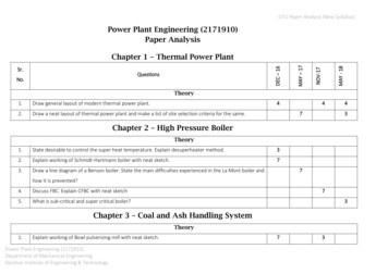
Power Plant Engineering (2171910) Paper Analysis Chapter 1 – Thermal Power Plant Sr. No. Questions – 16 Y – 17 V-17 Y - 18 Theory 1. Draw general layout of modern thermal power plant. 4 4 4 2. Draw a neat layout of thermal power plant and make a list of site selection criteria for the same. 7 3 Chapter 2 – High Pressure Boiler Theory 1 .