Transcription
Design and Construction of a Space-frameChassisBrendan. J. Waterman20348559School of Mechanical and Chemical EngineeringUniversity of Western AustraliaSupervisor: Assoc/Prof Adam WittekSchool of Mechanical and Chemical EngineeringUniversity of Western AustraliaFinal Year Project ThesisSchool of Mechanical and Chemical EngineeringUniversity of Western AustraliaSubmitted: November 7th, 20111
AbstractThe purpose of this project is to design and build a space-frame chassis for a race car tocompete in the FSAE-A competition as part of the UWA REV team. The FSAEcompetition is a competition for university students to design, build and race their ownopen wheeled race cars, there are also a number of static design events in thecompetition. The 2011 REV FSAE car will be powered by four electric motors with onemounted to each wheel’s upright. This is a new configuration for a FSAE car and assuch requires an entirely new chassis design that both supports the loads placed on it butalso weighs as little as possible. The chassis design implements structural battery boxeswhich have the dual purpose of protecting the driver from the batteries and addingstrength to the frame, this has not previously been used in any other FSAE car. Usingthese stressed battery boxes gives the chassis excellent torsional stiffness, yet the entireframe still weighs just over 40kg.2
AcknowledgementsI would like to thank Adam Wittek for his advice throughout this project, the REV teamand Swan Energy for funding the team for which the chassis has been designed, IanHooper for assisting with and providing the tools and facilities used for construction andEd Farrar for aiding in and providing the press used for weld testing. Finally I wouldlike to thank my family and partner for their support throughout the duration of mystudies.4
ContentsAbstract . 2Letter of Transmittal . 3Acknowledgements . 4Introduction . 7Literature Review . 10Design Process . 11Rules. 11Suspension Design and Forces . 15Packaging . 17Material . 17Manufacture . 18Square vs Round . 19Triangulation and Stressed Skins . 20Stressed Battery Boxes . 24Final Design . 27Front and rear sections . 27Roll hoops . 33Side impact structure . 37Front Bulkhead and Foot-well . 38Completing the Space-Frame . 39Battery boxes . 40Final Design Summary. 41Construction . 42Welding . 42Construction Process . 43Work completed . 485
Safety. 49Construction . 49Operation of the completed chassis . 51Torsion testing. 52Weld Testing . 53Conclusion . 59Future work . 60Construction . 60Chassis testing . 60Ultrasonic weld testing. 60Tuning . 60Future designs . 61References . 626
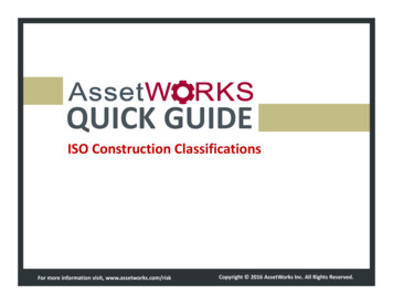
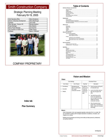
IntroductionThe purpose of this project is to design and construct a chassis for an electric poweredFormula SAE (FSAE) car to compete in the December 2011 FSAE-A competition. Thecompetition is for students to design, build and race small open-wheeled race carsagainst the clock in a number of events. The competition also includes some staticdesign events, where the cost and design of the car is judged by a panel. A uniquechassis design is required as the car will be powered by four electric hub motors, asopposed to the more conventional internal combustion engine mounted within theframe. This is the first time that electric hub motors will be used in the Australian FSAE competition and the first time four wheel-hub motors have been used in any FSAEcompetition around the world.In 2010 the REV team converted a previously used petrol FSAE chassis to electricpower in a similar configuration to the conventional combustion engine configuration.The chassis was made by UWA Motorsports and competed in the 2002 F-SAEcompetition. It was never intended for this petrol to electric converted car to compete inany FSAE event as it was only done as a prototyping exercise in an effort to investigatethe potential of an electric F-SAE car. The chassis no longer meets the requirements forthe FSAE competition as the rules for the competition have changed since 2002.Figure 1 2001 UWAM Chassis converted to electric power using a conventional inboard enginelayout7
There is much confusion over the meaning of the word chassis as discussed by Aird inthe book “The Race Car Chassis” (Aird,1997). In the early days of the automobilewhere coachbuilders were used, the term “chassis” was often used to describe the frame,engine and suspension as one complete unit. Essentially it described everything in a carother than the bodywork and cabin. In some other contexts “chassis” defines only theframe of the car with the drive-train and suspension being considered entirely separateitems. This latter interpretation of the word is what is used throughout this project,where the terms “chassis” and “frame” mean the same thing are interchangeable.When defined as above, a chassis is the component in a car that everything else attachesto. The most basic, common chassis design is referred to as the “Ladder Frame” due toits resemblance to a conventional lean-to ladder (Adams, 1992). A “Ladder Frame”consists of two long members that run the length of the automobile and are joined by aset of smaller members perpendicular to the two long members. The other componentsthat make up the vehicle are then mounted to this chassis. In the case of the LadderFrame; the body and engine are usually mounted to the top of the chassis with thesuspension being mounted below. This type of chassis dates back to horse-drawncarriages, originally made of wood, but generally being made of steel in automobilessince the 1900’s (Aird 1998). While being simple and easy to manufacture this type ofchassis generally has a poor torsional stiffness which makes it undesirable for a race car.In more recent times the chassis has evolved and in some cars it can be hard todistinguish between what makes up the body of a vehicle and what makes up thechassis. A monocoque chassis uses the body as the load carrying component and meansthat no separate chassis structure is needed. Entire panels carry the load rather thanspecific members, often these panels are the outermost parts of the body which meansthat a higher polar moment of Inertia (about the axis running from the front to the rearof the car) is achievable. A high polar moment of inertia about the longitudinal axis is adesirable property for a chassis as it is directly related to torsional stiffness (Aird, 1997).The drawback of a monocoque chassis is that they can be difficult to manufacture andare comparatively expensive in small production numbers, which is why a monocoquewill not be used in this project.8
A space-frame chassis lies somewhere between the ladder chassis and the monocoque, itis constructed from an arrangement of small, simple members which make up a largerframe. A space-frame is analogous to a truss style bridge which is made up of small(generally straight) members in a triangular pattern which are always in purecompression or tension. By having members in pure compression or tension (ie. they donot experience bending forces) they do not have to be oversized to support bendingloads (Budynas,2011).Light weight is a primary goal for all components in a race car as a lower weightrequires less force to accelerate by the same amount. Newton’s 2nd law says;𝐹𝑜𝑟𝑐𝑒 𝑀𝑎𝑠𝑠 𝐴𝑐𝑐𝑒𝑙𝑒𝑟𝑎𝑡𝑖𝑜𝑛So given the same force, a lighter car will accelerate quicker. This applies in alltransient conditions including braking and cornering. If a car accelerates quicker, then itreaches a higher speed quicker and therefore it is faster, which is the purpose of a racecar. So wherever possible everything in a race car should be as light as possible.Stiffness is also a desirable property for a race car chassis to have. The suspension forthe 2011 REV FSAE car has been designed by another student under the assumptionthat the chassis acts as a rigid body (Kiszko,2011) so if the chassis deforms too muchunder load then the suspension is unlikely to work as desired.The chassis is being built for the UWA REV team who have previously converted twoproduction cars to electric power, a Lotus Elise and a Hyundai Getz. The FSAE carbeing build in the REV team is being funded by a solar panel company Swan Energy.The sponsor is providing 25 000 to the team to construct the car and although the teamhave secured the money in advance of competing in the competition, the performance ofthe car at the competition will affect the sponsor’s willingness to sign up for futuresponsorship deals with the UWA REV team.9
Literature ReviewBefore commencing any design work it is useful to see what is already being done byothers in the same field. As mentioned in the introduction the 2011 REV FSAE car willbe powered by a unique drive-train and as such requires a unique chassis, however thebasic principles of chassis design still apply.For a background into chassis design a relevant text was discovered and reviewed. Thebook published by Penguin Books is entitled “The Race Car Chassis” and is written byForbes Aird. The book discusses different types of chassis’ and the history of chassisevolution. It focuses primarily on space-frames and stressed skin type chassis’ which ishighly relevant to this project due to the low cost, readily available materials used andrelatively simple manufacturing processes. “The Race Car Chassis” is somewhat of areview of different chassis designs used by different race cars, discussing chassis’ fromall manner of classes such as drag, circle track and even passenger cars. The book alsocovers the different materials commonly used to construct chassis’ and lists eachmaterial’s advantages and disadvantages.Aird includes information regardingsuspension and other loads on the chassis and how these should be supported.Significantly the book covers the design process for space-frame chassis’ includingmaterial selection, tube sizing and member arrangement. “The Race Car Chassis” wasoriginally written in 1997 which means it is not up to date with the latest and mostadvanced technology however space-frames have not changed significantly in recentyears so the book is still highly relevant. The main advancements that have been madein chassis technology since 1997 are in composite monocoque frames which are notrelevant to this project due to their relatively high cost and the REV team’s limitedbudget. Overall this is a very useful book for the project covering much relevantinformation without any significant bias.Another text that was analysed for this project was “Chassis Engineering” written byHerb Adams and published by Penguin Books. The book was first published in 1992making it slightly older than “The Race Car Chassis” described above. Contrary to Airdand this project, Adams considers the chassis to include suspension and bodyworkcomponents so the book contains a large amount of information about suspension setupand tuning as well as tyre characteristics which is not relevant for this project as thesuspension for the car has already been designed by another student. Much of the frame10
design information covered in this book is the same as found in “The Race Car Chassis”which serves to validate and confirm the information already found rather than actuallyproviding any new information. This does not make the book useless though as it isuseful to have a second source back up the information already gathered. “ChassisEngineering” does include some useful pictures of various chassis design models beingtested in torsion which serve to give a good idea of what designs work well and whichones don’t. This information is not quantitative and cannont be directly applied in thedesign process, but it is likely to be useful in that the design will have a better startingpoint.The University of Western Australia has a history of competing at the FSAE eventsuccessfully. UWA Motorsport (UWAM) has been competing at the event since 2001,winning the Australian competition in 2005 and 2007 and even winning theinternational competition in 2008. UWAM has been using carbon fibre monocoquechassis’ since 2003, as discussed earlier the 2011 UWA REV team would not be using acarbon monocoque due to the cost associated.Design ProcessDesign RequirementsThe design of the chassis must work around a number of parameters and constraints inorder for it to perform well and for it to be eligible to compete in the competition. Theserequirements can be broken into several categories which will be discussed below. Ifany of these requirements are not met, the consequences range from sub-optimalperformance to not being eligible to compete in the competition or even chassis failure.So it is clear that all requirements must be carefully considered and even re-visitedwhen designing and building the chassis.RulesThe first thing that must be considered when designing the chassis is the 2011 FSAE-Arules, there is no point in designing a chassis if it will not be allowed to compete in thecompetition for which it is designed. The FSAE rules require a front and rear roll hoop,a side impact structure, a front bulkhead and supports for the aforementionedcomponents be integrated into the chassis. By representing graphically these11
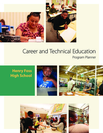
requirements one may create a “minimum chassis’ Figure 2 which shows the simplestpossible configuration of members that include the required components mentionedabove. Figure 2 is a side view diagram of what this “minimum chassis” looks like, itdoes not consider driver ergonomics, cockpit entry or suspension points etc, and ismerely a pictorial representation of some of the required members.Figure 2. Pictorial representation of the members required by the FSAE rules.The FSAE rules define a minimum size for all the chassis members shown in Figure 2and for some other members not shown. To avoid adding un-necessary weight, thechassis design should make best use of the required members so that as few possibleadditional members are needed. This is where much of the design work needs to bedone for the project because as the rules limit many of the members, little design workcan be done in optimizing the size of the chassis members.Figure 3 2011 Formula SAE Rules for Member size. Adapted from 2011 Formula Student rules(SAE, 2010)12
The FSAE rules also require a firewall barrier to isolate the batteries from the driver, itmust cover the vertical and horizontal portions of the battery box that face the driver.2.6mm aluminium sheet is suggested for this firewall but 1mm steel has been approvedas an alternative by the FSAE-A rules committee. The chassis must also providesufficient space for cockpit entry, where the driver enters the cockpit. FSAE rulesrequire a template shown in Figure 4 be able to pass vertically through the cockpitopening until it reaches the height of the top bar in the side impact structure.Figure 4 Cockpit entry templateA sufficiently large foot-well area must also be present in the chassis for the driver’slegs and feet. The foot-well is the area where the accelerator and brake pedals arelocated and is where the driver’s legs lie when driving. The foot-well area lies betweenthe front suspension pivots so the design will have to work around this area carefully sothat the suspension loads are adequately supported, to avoid damaging the chassis andpotentially injuring the driver. Figure 5 shows the template that must be able to passhorizontally through the foot-well according to the FSAE rules.13
Figure 5 Foot-well clearance templateFSAE rules require that a 95th percentile male can drive the car with clearance to thetwo roll hoops. A template of a 95th percentile male as shown in Figure 6 must be ableto fit in the seat with a minimum of 2 inches (50.8mm) clearance to a tangential linerunning from the top of the front roll hoop to the top of the main roll hoop. As none ofthe drivers in the REV team are as tall as a 95th percentile male then if the design fits thetemplate it will be known to fit any drivers from the team. The roll hoops must thereforebe sized to fit this 95th percentile male template.14
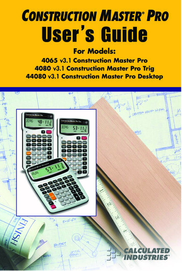
Figure 6 95th Percentile Male TemplateSuspension Design and ForcesIn addition to ensuring the design meets the FSAE competition rules there are predefined suspension points which the chassis must provide support and attachment for.The suspension system for the 2011 REV FSAE car has been designed in anotherstudent’s thesis (Kiszko, 2011) and in order to maintain the designed suspensiongeometry, the suspension points should not be moved from their designed locations.To produce a space-frame chassis with sufficient stiffness and to ensure the chassis issafe, the design must be constructed so that bending moments are not introduced intoany of the chassis members. Figure 7 shows a basic layout of the ends of the chassis thatare required to hold the suspension pivots in their correct locations.15
Figure 7 Basic ends of the chassis that hold the suspension arms in place.(Forces are mirrored on the opposite side of the chassis)The suspension design uses unequal length double A-arm suspension with inboardmounted springs connected to the wheels via pull-rods and bell-crank rockers. The Aarms are mounted to the chassis via spherical bearings which transfer loads into thechassis in a plane parallel to the ground (shown as the red arrows in Figure 7). Forcesfrom the A-arms occur when the car is accelerating which includes; forwardacceleration, braking and cornering. Ideally the A-arm forces should act as near aspossible to a node in the chassis so the reaction forces consist of pure compressive andtensile forces in chassis members. Nodes (joints) in the chassis also have the leastamount compliance in the chassis, which improves suspension performance as thewheels will be better located and deflect less under loads. The pull-rod and spring forcesact in a plane parallel to the front bulkhead (the forces are shown by the green arrows inFigure 7). Forces from the suspension springs and rockers are present even when the caris stationary, resting on its wheels. However these forces increase under suspensionmovement which occurs as a wheel runs over a bump and/or when the chassis pitches,dives or rolls while driving. Additional diagonal members must be added to the basicframe shown in Figure 7 to prevent the spring and rocker forces (currently acting on themiddle of the member) from creating bending moments in the horizontal transposemembers.16
PackagingIn conjunction with meeting all the rules and providing attachments for the suspensioncomponents, the chassis must also fit the driver and all the required components into theframe. The most significant of these components being: Seat and driver harnesses Batteries Electronic control components (motor controllers, BMS, Sensors etc.) Driver controls (steering wheel, pedals, switches etc)The driver must be considered first as he/she will be bigger than any other component inthe car and must fit comfortably. Driver ergonomics must be considered to ensure thedriver is able to complete each driving event comfortably. Points are also awarded in thestatic phase of the competition for driver ergonomics so it is beneficial to pay closeattention to this area while designing. As mentioned in the rules section, the 95thpercentile male must be able to fit in the chassis with clearance to the front and rear rollhoops soFortunately most of the other required components can be made to fit into the smallremaining spaces as their shape is quite flexible. The batteries will be made from 600small cylindrical cells meaning their required volume is significant but their shape canbe made to suit the chassis design. However a relatively simple shape is desirable inorder to prevent un-necessary complexity in connecting the cells. A motor controller isrequired to control each of the 4 motors and should be mounted as close to each motoras practically possible. The motor controllers must be mounted as close to the motorthat they are controlling as possible so the front motor controllers can be mounted to theback of the front bulkhead, in front of the driver’s feet. The remaining rear motorcontrollers and other electronic control units are able to be located in the rear section ofthe chassis behind the driver, space which is otherwise unused as the 2011 REV FSAEcar does not have an inboard mounted engine.MaterialIt was decided that the frame would be constructed from steel due to its availability andrelatively low cost. There are many different grades of steel available however many ofthe FSAE teams around the world from universities such as UWA (for the rear spaceframe section), Curtin, RMIT, Missouri S&T use 4130 SAE grade steel (which contains17
Chromium and Molybdenum alloying elements) due to its higher yield strength. In thefirst part of the design phase when the chassis material was chosen, the team had alimited budget which resulted in the decision to use mild steel instead of 4130.Lightweight and stiffness are the most important properties of a chassis and the stiffnessof the completed chassis will be affected by the stiffness of the material from which it isbuilt. Material stiffness is known as Young’s Modulus and the controlling mechanismfor stiffness in a material is the inter-molecular forces. So stiffness or Young’s Modulusis a material constant which cannot be significantly changed by any mechanical orchemical processes. Alloying elements also have little effect on stiffness meaning thatmore expensive grades of steel have the same stiffness as mild steel (Callister, 2007).This justifies the decision to use mild steel for chassis construction as more expensivesteels are unlikely to improve the chassis’ stiffness.Aside from cost there are other advantages to using mild steel over more expensivealloy steel, it is easy to machine and weld, also it does not become brittle in the heataffected zone when welding. (Black,2008) The FSAE rules also state that using strongersteels does not allow the use of smaller chassis members so there would be no weightadvantage in using the more expensive SAE grade 4130 steel for these members. Thedownside to using mild steel comes with its lower yield strength, in the event of acollision or some other impact the chassis may become damaged at a lower stress than ifit were built from 4130. This disadvantage is also present when there are small impactson the chassis, an example of this would be small stones being picked up off the road bythe tyres and hitting the chassis. The chassis may dent and its structural integrity may becompromised easier than an equivalent alloy steel chassis. In order to prevent this fromendangering the driver, routine checks of the chassis for dents and damage must bemade prior to anyone driving the car.ManufactureIn order to improve manufacturability, square tubing may be used for many of thehorizontal frame members. This makes cutting planar joints easier and simplifiessuspension mounting points. Due to availability 25.4mm x 25.4mm x 1.4mm squaretubing was used, which is larger than the minimum size required by the FSAE rules inFigure 3.18
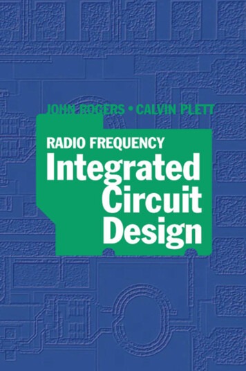
On many chassis designs a significant amount of construction time is taken up bymaking jigs to hold the fame in place during welding. Making a jig is very labourintensive and it can even use as much material as the chassis itself. To improve themanufacturability of the chassis it should be designed so that it is “self jigging”, whichmeans that it can be constructed in separate parts which are then joined together. Thissignificantly reduces the time and material required to make the chassis which greatlyreduces the cost. It should be noted that this approach is suitable for a one off processwhich is the case for the construction of this chassis. However if a number of the samechassis are needed to be made then it the cost of making a jig is justified as it decreasesthe amount of time required to build each individual chassis (Black,2008).Square vs RoundTo assess the potential advantage or disadvantage using square instead of round tubingsome simple calculations should be made from the pipes’ cross sections. Figure 8 showsthe closest pipes sizes to the minimum required by the FSAE Rules that were available.The round tube used is the same size as the minimum size required by the FSAE ruleshowever the square tube has thicker walls than the minimum required.Figure 8 Dimensions of the square and round tubing used19
RoundSquare%DifferenceCross Sectional Area [m]119.6318 132.717510.93829Mass per Unit length [kg/m]0.933128 1.03519710.93829Second Moment of Area [mm4]8508.815 12688.02*49.11618Buckling Load for 1m Length** [N] 16795.73 25045.1549.11618Figure 9 Data calculated for the available square and round pipes*Lowest Ixx for square tube, calculated about central axis parallel to face.**For mode 1 buckling where both ends are free to pivot.Figure 9 shows the weight compromise for using the square tubing, the compressivestiffness of each tube is proportional to its area so it is not shown. From the table it canbe seen that with just an 11% increase in weight a 50% increase in yield strength isobtained if buckling is the failure mode. Using one or more square pipes as part of theside impact structure will make the chassis stronger than an equivalent structure usingonly round members which is what the 2002 UWAM petrol-electric converted chassisuses.By using square tubing for the horizontal sections, the joints between members in the
Herb Adams and published by Penguin Books. The book was first published in 1992 making it slightly older than“The Race CarChassis” describedabove. Contrary to Aird and this project, Adams considers the chassis to include suspension and bodywork components so the book contains