Transcription
Slider – Crank Mechanism forDemonstration and ExperimentationMQPAdvisor: Eben C. CobbERIC BRIGHAMCHRIS DESTEFANOZACHARY KILLOYDate Submitted: April 25, 2013
Slider – Crank Mechanism for Demonstration and ExperimentationAbstractThe slider-crank mechanism is a particular four-bar linkage configuration that exhibits bothlinear and rotational motion simultaneously. This mechanism is frequently utilized in undergraduateengineering courses to investigate machine kinematics and resulting dynamic forces. The position,velocity, acceleration and shaking forces generated by a slider-crank mechanism during operation canbe determined analytically. Certain factors are often neglected from analytical calculations, causingresults to differ from experimental data. The study of these slight variances produces useful insight. Thefollowing report details the successful design, fabrication and testing of a pneumatically powered slidercrank mechanism for the purpose of classroom demonstration and experimentation. Transducersmounted to the mechanism record kinematic and dynamic force data during operation, which can thenbe compared to analytical values. The mechanism is capable of operating in balanced and unbalancedconfigurations so that the magnitude of shaking forces can be compared. The engine was successfullymanufactured and operates as intended. Data recorded by the device’s accelerometers is comparable tocalculated values of acceleration and shaking force.Page i
Slider – Crank Mechanism for Demonstration and ExperimentationContentsAbstract .iContents.1Executive Summary . 3Design Description . 4OBJECTIVE. 4TASK SPECIFICATIONS. 4DECISION MATRIX . 5BACKGROUND .6SOLID MODELING. 7DESIGN FOR MANUFACTURABILITY. 9TRANSDUCER SELECTION . 11Analysis . 13KINEMATIC ANALYSIS. 13Position Analysis . 13Velocity Analysis . 15Acceleration Analysis . 17Dynamic Force Analysis .19TORSIONAL STRESS ANALYSIS OF CRANKSHAFT . 28FINITE ELEMENT ANALYSIS OF CRANKSHAFT . 32TORSIONAL VIBRATION ANALYSIS OF CRANKSHAFT . 41CROSSHEAD GUIDE DEFLECTION ANALYSIS. 42CROSSHEAD GUIDE NATURAL FREQUENCY ANALYSIS . 44DAMPER SELECTION THROUGH VIBRATION ANALYSIS. 45PIN STRESS ANALYSIS . 47PRELIMINARY VALVE DESIGN.48Cylinder Pressurization Analysis.48Experimental Evaluation of Mass Flow through System .48Manufacturing.50LIMITATIONS AND VARIATIONS .50Page 1
Slider – Crank Mechanism for Demonstration and ExperimentationCRANKSHAFT OPERATIONS AND FOURTH AXIS MACHINING . 51MACHINING IMAGES . 56Results of Initial Testing. 62SLIDER ACCELERATION AND CYLINDER PRESSURE . 62SHAKING FORCES. 65Comparison of Analytical and Experimental Results. 68Conclusion. 70Discussion. 71Recommendations for Future MQPs . 72Figures . 74Bibliography . 77Appendices . 78Page 2
Slider – Crank Mechanism for Demonstration and ExperimentationExecutive SummaryThe slider-crank mechanism is a particular four-bar linkage configuration that converts linearmotion to rotational, or vice versa. Internal combustion engines are a common example of thismechanism, where combustion in a cylinder creates pressure which drives a piston. The piston’s linearmotion is converted into rotational motion at the crank through a mutual link, referred to as theconnecting rod. As the geometry of the crank forces the conversion of linear motion to rotational,shaking forces are generated and applied to the crank’s housing. These shaking forces result invibrations which impede the operation of the engine.The slider-crank mechanism is frequently utilized in undergraduate engineering courses toinvestigate machine kinematics and resulting dynamic forces. The position, velocity, acceleration andshaking forces generated by a slider-crank mechanism during operation can be determined analytically.Certain factors are often neglected from analytical calculations, causing results to differ fromexperimental data. The assumption is frequently made that the crankshaft’s angular velocity is constant.In reality, angular velocity is slightly higher on the power stroke than the return stroke. The study ofthese slight variances produces useful insight into the characteristics of piston driven engines.The following report details the successful design, fabrication and testing of a pneumaticallypowered slider-crank mechanism for the purpose of classroom demonstration and experimentation.Complete analysis of the engine’s kinematics was performed, assuming a constant angular acceleration.Shaking forces of the unbalanced mechanism were calculated and balancing weights were designed forstatically and dynamically balanced configurations at the same constant angular velocity. Transducersmounted to the mechanism were used to record kinematic and dynamic force data during operation,which was then compared to the analytical values.The engine was successfully manufactured and operates as intended. Data recorded by thedevice’s accelerometers is comparable to calculated values of acceleration and shaking force.Satisfactory operation of the engine was achieved with minimal tuning. The engine is capable ofoperating at angular velocities ranging from 80 to 330 RPM, using a balancing weight optimized for200RPM. Sustained motion is achievable with cylinder pressures as low as 4.5psi, with a loss of only 2 psithrough the system. The reduction in shaking force achieved through use of the balance weights isapparent both visually and in recorded data. All experimental values were reasonable when comparedwith analytical calculations.Page 3
Slider – Crank Mechanism for Demonstration and ExperimentationDesign DescriptionObjectiveThe objective of this MQP is to fabricate a working model of a slider crank mechanism thatdemonstrates the associated motion and provides means to measure kinematic properties, dynamicforces and cylinder pressure in various states of balance.Task Specifications1. The slider-crank mechanism’s motion must be visible.2. The mechanism must be able to sustain motion when acted on by a driving force.3. Removable balance weights must be incorporated into the design.4. The mechanism must be capable of operating in both balanced and unbalanced states.5. A means of measuring and recording the kinematic and dynamic characteristics of the slidercrank mechanism’s motion must be incorporated into the design.6. All components of the mechanism must be exhibit a safety factor of 5 in regards to static failure.7. The mechanism, all equipment required for operation and data acquisition must be portableand self-contained.8. The total width of the unit must not exceed 2.5 feet, to allow for transport through a doorway.9. The mechanism must be operable by one individual.10. All moving components must operate behind a safety shield.11. The mechanism must be manufactured within the MQP’s cost constraints.12. Design, manufacturing and experimentation must be completed within the allotted time.Page 4
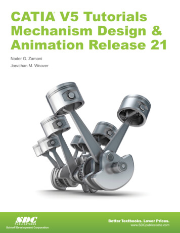
Slider – Crank Mechanism for Demonstration and ExperimentationDecision MatrixFigure 1: Decision Matrix used to rank proposed designsPage 5
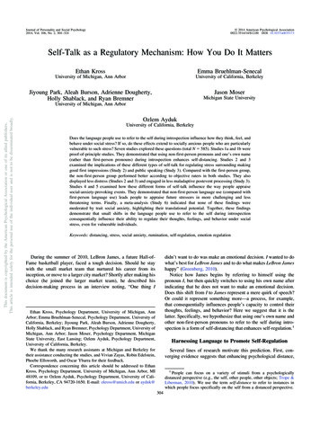
Slider – Crank Mechanism for Demonstration and ExperimentationBackgroundThe assembly of a piston, cylinder, connecting-rod and crankshaft is the classic form of theslider-crank mechanism. In general a slider crank transmits motion generated by the lineardisplacement of the piston by a working fluid to rotational motion of a shaft. There are manyapplications of slider cranks and among the most common are engines. The use of these mechanismsfor power generation began with the steam engine in the late 18th century and has developed intopossibly its most recognizable form as the current day internal combustion engine.A single pistonengine model could serve as a functional, eye-catching example of a slider-crank.Elmer’s Standby Single-Acting, Single Piston Pneumatic Engine:The “Standby” single acting, single piston pneumatic engine is one example of a slider crankmechanism. This engine utilizes a piston-wrist-pin-connecting rod construction that resembles anautomotive engine. This type of engine provides a clear visual of the kinematics of a slider crank. Thedesign can be powered by compressed air or steam and is driven by pressure applied to one side of thepiston within the cylinder. The single acting nature of this engine also more closely resembles theoperation of an internal combustion engine. The design is simpler than alternative pneumatic andsteam engines based on its lack of external eccentric valve gear. The design uses grooves on thecrankshaft to port air into and out of the cylinder at specific times in its rotation.By attaching pressure transducers andaccelerometers to this design it wouldbe possible to relate cylinder pressuresto the mechanism’s kinematics. Thecrankshaft in this design would also beeasily modified in order to createdetachable balancing weights todemonstrate shaking forces forunbalanced, overbalanced and perfectlybalanced situations.Figure 2: Elmer's Standby Model EnginePage 6
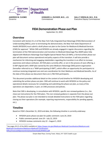
Slider – Crank Mechanism for Demonstration and ExperimentationSolid ModelingThe Standby engine utilizes a valve system which is integrated into the crankshaft. This designcharacteristic was incorporated into the demonstration device.Figure 3: Isometric View Solid Model of Slider Crank MechanismFigure 4: Top View Solid Model of Slider Crank MechanismPage 7
Slider – Crank Mechanism for Demonstration and ExperimentationFigure 5: Assembly Drawing for Slider Crank MechanismFigure 6: (Left) Solid Model of Crankshaft Top View; (Right) Solid Model of Crankshaft Isometric ViewPage 8
Slider – Crank Mechanism for Demonstration and ExperimentationDesign for ManufacturabilityWhen the group finalized the design there were some changes made in order to make themachining of the components both simpler and less time intensive. Some changes included removingcertain features which did not generate any real benefit to the design. The group also designed themechanism to be feasibly manufactured with the machines and standard tooling in the Washburn Shops.This included the use of CNC machining specifically using the HAAS VM-3 Mold Maker, the HAAS VF-4Milling Center and the HAAS SL20 Lathe. Once the design had been finalized the group was able toapply tolerancing to sliding, press-fit and rotating parts.In defining the dimensions of the parts the group had to account for certain limitations intooling, machine capability as well as the errors which may be generated through measurements of theindividual components. For parts such as the cylinder support, the slide-support and the crank supportthe exterior dimensions (that is to say dimensions other than the bores) were not critical for thefunctionality of the design. This was not the case, however, for parts such as the piston, the sleeve, thecrank-shaft and the bearing. Each of these individual parts required extensive tolerancing, both indesign and manufacture.The group referred to the Machinery’s Handbook (28th Edition) for much of the required fits. Togenerate a free rotating yet accurate fit between the crankshaft and the bearing the group referred tothe American National Standard Running and Sliding Fits Table (ANSI B4.1-1967), and decided on using aRC3 Precision Running Fit. The use of this fit is chiefly applied to precision machinery where low tomoderate surface speed is expected and light journal pressures are encountered without appreciabletemperature change. The use of this fit was employed in order to maintain an airtight yet free-runningfit between the shaft and the bearing. This fit for a shaft of the range 0.71-1.19 generates a range ofclearance from 0.0008-0.0021”. The crankshaft diameter was designed to be 1.125” so a value of 0.001”was chosen for the clearance. This clearance as dictated by the table could be produced by machiningthe shaft to a range of -0.0008 to -0.0013 of the nominal size while machining the bushing (hole) to arange of 0.0008 to the exact nominal size. The group used the table again to generate a designtolerance on the piston and cylinder but this time for the diameter range of 1.97-3.15. The piston andthe cylinder were designed to have a diameter of 2”. This generated a clearance in the range of 0.0012to 0.0031 with the piston diameter ranging from -0.0012 to -0.0019 from its nominal size and thecylinder ranging from 0.0012 to its nominal size.Page 9
Slider – Crank Mechanism for Demonstration and ExperimentationIn addition to the rotating and sliding fits certain parts required press and interference fits whichwere also determined using the Machinery’s Handbook. These fits were required for the fit betweenthe cylinder stands and cylinder sleeves, the bearings in the connecting-rod as well as the bushings forthe slide and slide-rail interface. All of these fits fell within the FN1 Standard for Force and shrink fits.These fits range by the diameter of the “shaft” and “hole diameter and are listed below: Large Bearing Connecting Rod:Hole: 0.8755”-0.8750”; Shaft: 0.8757”-0.8761”; Interference: 0.0002”-0.0011”Small Bearing Connection Rod:Hole: 0.5004”-0.5000”; Shaft: 0.5005-0.5008”; Interference: 0.0001”-0.0008”Cylinder Sleeve/Cylinder Stand:Hole: 2.5007”-2.5000”; Shaft: 2.5013”-2.5018”; Interference: 0.0006”-0.0018”Slide Bushing/Slide:Hole: 0.3754”-0.3750”; Shaft: 0.3755”-0.37575”; Interference: 0.0001”-0.00075”Page 10
Slider – Crank Mechanism for Demonstration and ExperimentationTransducer SelectionPCB 302A piezoelectric uniaxial accelerometer:The PCB 302A accelerometer is rigidly fixed to the crosshead. Linear acceleration data is recorded duringoperation to compare with calculated values of the slider’s acceleration. Position and velocity of theslider can be derived by integrating the recorded acceleration curve. A charge amplifier is required tooperate the piezoelectric accelerometers used in this project. The PCB 482A16 four channel amplifierwas selected because it can accommodate all accelerometers simultaneously. A data acquisition unit isutilized in conjunction with LabView programs to record and save data from all of the mechanism’stransducers.PCB 308B piezoelectric uniaxial accelerometer:The crankshaft is supported by the bearing, which is pressed inside the bearing support. Two PCB 308Baccelerometers are rigidly fixed to the bearing support. One accelerometer is positioned along theslider’s axis of translation, while the other is perpendicular to it. During operation, linear accelerationdata is recorded in both directions. This data is used to determine the shaking forces generated by themechanism along both axes and will be compared to analytical values. The PCB 308B is ten times moresensitive than the PCB 302A and was selected for this scenario due to the comparatively low magnitudeof acceleration experienced by the bearing support.Page 11
Slider – Crank Mechanism for Demonstration and ExperimentationBLH 404215 pressure transducer:The BLH 404215 pressure transducer operates in the range of 0 to 100 psi. The required excitationvoltage of 10 Vdc is supplied by a 2310 signal conditioning amplifier. This transducer is connected byrigid piping to the mechanism’s cylinder and records variations in pressure during operation. Thepressure curve generated by the device is similar to that of a single acting steam engine. This data maybe used to determine the input pressure that results in maximum operational speed.Page 12
Slider – Crank Mechanism for Demonstration and ExperimentationAnalysisKinematic AnalysisThe kinematics of the slider-crank mechanism are evaluated at a rotational speed of 200rpm. All of thefollowing kinematic and dynamic force equations are taken from Norton’s Design of Machinery.Position AnalysisSlider PositionFigure 7: Slider Position vs. Crank AnglePage 13
Slider – Crank Mechanism for Demonstration and ExperimentationCrank PositionFigure 8: Crankshaft X Displacement vs. Crank AngleFigure 9: Crank Y Displacement vs. Crank AnglePage 14
Slider – Crank Mechanism for Demonstration and ExperimentationVelocity AnalysisSlider VelocityFigure 10: Slider Velocity vs. Crank AnglePage 15
Slider – Crank Mechanism for Demonstration and ExperimentationCrank VelocityFigure 11: X Component of Crank Velocity vs. Crank AngleFigure 12: Y Component of Crank Velocity vs. Crank AnglePage 16
Slider – Crank Mechanism for Demonstration and ExperimentationAcceleration AnalysisSlider AccelerationFigure 13: Slider Acceleration vs. Crank AnglePage 17
Slider – Crank Mechanism for Demonstration and ExperimentationCrank AccelerationFigure 14: X-Component of Crank Acceleration vs. Crank AngleFigure 15: Y-Component of Crank Acceleration vs. Crank AnglePage 18
Slider – Crank Mechanism for Demonstration and ExperimentationDynamic Force AnalysisShaking ForcesShaking force is defined as the sum of all forces acting on the ground plane of the system.Figure 16: Slider-Crank Coordinate System and VariablesUnbalanced ConfigurationFigure 17: Unbalanced Slider-Crank model (see Norton Design of Machinery fig. 13-12 p.618)Page 19
Slider – Crank Mechanism for Demonstration and ExperimentationM2a has a mass*radius product equal to that of the unbalanced crankM3a is equal to 2/3 the mass of the connecting rodM3b is equal to 1/3 the mass of the connecting rodEffective mass at crank (lumped mass A) Ma MaEffective mass at slider (lumped mass B) Mb M3b (slider mass)Figure 18: X-Component Shaking Force vs. Crank Angle (Unbalanced)Page 20
Slider – Crank Mechanism for Demonstration and ExperimentationFigure 19: Y-Component Shaking Force vs. Crank Angle (Unbalanced)Figure 20: Total Magnitude of Shaking Force (Unbalanced)Page 21
Slider – Crank Mechanism for Demonstration and ExperimentationStatically Balanced ConfigurationFigure 21: Statically balanced slider-crank model (see Norton Design of Machinery fig13-23 p. 632)M2a has a mass*radius product equal to that of the unbalanced crankM3a is equal to 2/3 the mass of the connecting rodM3b is equal to 1/3 the mass of the connecting rodMa M3a M2aMa’ M3a’ M2a’Effective mass at crank (lumped mass A) Ma Ma-Ma’ 0Effective mass at slider (lumped mass B) Mb M3b (slider mass)Page 22
Slider – Crank Mechanism for Demonstration and ExperimentationFigure 22: X-Component Shaking Force vs. Crank Angle (Statically Balanced)Figure 23: Y-Component Shaking Force vs. Crank Angle (Statically Balanced)Page 23
Slider – Crank Mechanism for Demonstration and ExperimentationFigure 24: Total Magnitude Shaking Force (Statically Balanced)Dynamically Balanced ConfigurationFigure 25: Dynamically Balanced Slider-Crank Model (see Norton Design of Machinery fig 13-23 p.632)Page 24
Slider – Crank Mechanism for Demonstration and ExperimentationM2a has a mass*radius product equal to that of the unbalanced crankM3a is equal to 2/3 the mass of the connecting rodM3b is equal to 1/3 the mass of the connecting rodMa M3a M2aMa’ M3a’ M2a’1/2Mb Mp 2/3Mb (the exact value depends upon the optimal operating speed)Effective mass at crank (lumped mass A) Ma Ma-Ma’-Mp -MpEffective mass at slider (lumped mass B) Mb M3b (slider mass)Page 25
Slider – Crank Mechanism for Demonstration and ExperimentationFigure 26: X-Component Shaking Force vs. Crank Angle (Dynamically Balanced)Figure 27: Y-Component Shaking Force vs. Crank Angle (Dynamically Balanced)Page 26
Slider – Crank Mechanism for Demonstration and ExperimentationFigure 28: Total Magnitude Shaking Force vs. Crank Angle (Dynamically Balanced)Page 27
Slider – Crank Mechanism for Demonstration and ExperimentationTorsional Stress Analysis of CrankshaftThe engine’s crankshaft rotates about the X axis as it is driven by the connecting rod. The geometry andloading of the crankshaft will produce significant torsional stress in the shaft, the maximum value ofwhich must be evaluated. In order to represent a worst-case stress scenario, the assumption is madethat one end of the shaft is fixed by the flywheel while the other is subjected to the torque generated bythe device under maximum operational speed. The geometry and loading of the crankshaft will result inminimal bending so it will be neglected. A conservatively large value for maximum operational angularvelocity is assumed to be ω 500 rpm (52.4 rad/s).Figure 29: Crank-Shaft Fixtured for 4th Axis MachiningAcceleration 110 m/s2The primary shaking force calculated previously using the lump mass model is selected as the magnitudeof force applied to the crankshaft through the connecting rod pin connection.Shaking force 185 NPage 28
Slider – Crank Mechanism for Demonstration and ExperimentationFMAX 185NCrank Radius 1.5”ZYFBD of CrankshaftFigure 30: Free Body Diagram for Crankshaft Side ViewShaft torque 7.05 NmT 7.05 NmZXYL 3”FBD of CrankshaftFigure 31: Free Body Diagram of Crankshaft Isometric ViewThe polar moment of inertia (J) of the crankshaft’s cross section is approximated by assuming a uniformhollow shaft of outer diameter 1.125”, inner diameter 0.375” and unsupported length L 3”.Area moment of inertia 6.48E-8 L4A stress concentration factor (K) must be applied toAreas of greateststress concentrationapproximate the amplification of stress caused by the nonuniform valves which cut into the shaft. The effect of theseareas of stress concentration will be evaluated by applyingempirical data from Walter Pilkey’s Peterson’s StressConcentration Factors.Figure 32: Stress Concentration LocationsPage 29
Slider – Crank Mechanism for Demonstration and ExperimentationOne scenario presented in Pilkey’s text resembles the crankshaft’s geometry and loading. The model isthat of a hollow shaft undergoing torsion; an additional through hole exists perpendicular to the axis ofrotation. Relevant empirical data is presented in the following chart.Figure 33: Stress Concentration TablePage 30
Slider – Crank Mechanism for Demonstration and ExperimentationThe empirical data must be extrapolated slightly beyond the chart’s limits. A conservative estimation ofK 7 will be incorporated into the calculation of torsional stress.Torsional stress 10.9MPaThe crankshaft is machined from 1018 carbon steel whi
Apr 25, 2013 · temperature change. The use of this fit was employed in order to maintain an airtight yet free-running fit between the shaft and the bearing. This fit for a shaft of the range 0.71-1.19 generates a range of clearance from 0.0008-0.0021”. The crankshaft diameter was designed to be