Transcription
Journal of Technology and Science EducationFLIGHT MECHANICS EXPERIMENT ONBOARD NASA’S ZERO GRAVITY AIRCRAFT112Kyle R. Matthews , Samira A. Motiwala , Donald L. Edberg , Eduardo García-Llama31Aerospace Engineering Department, California State Polytechnic gmail.com, samotiwala@csupomona.edu2Professor, Aerospace Engineering Department, California State Polytechnic na.edu3GBTech, Inc. (NASA’s Johnson Space Center, Flight Mechanics and Trajectory Design vReceived August 2011Accepted February 2012AbstractThis paper presents a method to promote STEM (Science, Technology, Engineering, and Mathematics)education through participation in a reduced gravity program with NASA (National Aeronautics and SpaceAdministration). Microgravity programs with NASA provide students with a unique opportunity to conductscientific research with innovative and creative solutions through hands-on experimental design and testing inreduced gravity conditions. A group of undergraduate students from California State Polytechnic University,Pomona, participated in the NASA’s SEED (Systems Engineering Educational Discovery) Reduced GravityProgram, which focuses on addressing systems engineering challenges in microgravity. The team worked with aNASA Principal Investigator on a project to build and fly a prototype test article to demonstrate emergencyatmospheric reentry with single-axis control. Through this experience, the team was able to gain hands-onexperience with spacecraft instrumentation and learn valuable lessons in teamwork and systems engineeringthat can be applied to real-world situations. As part of the SEED program, the team shared its experience withlocal high schools in order to spark interest in STEM-related fields in the next generation of scientists andengineers.Keywords - NASA Microgravity University, STEM, SEED, reduced gravity program, zero gravity.----------1INTRODUCTIONThe STEM (Science, Technology, Engineering, and Mathematics) education initiative is part of the NSF’s(National Science Foundation) approach to incorporating technology, engineering, mathematics and science inthe classroom in order to encourage excellence in these areas. Participants integrate college-level material intohigh school courses to provide hands-on learning at young ages (U.S. Department of Labour, 2007; Bybee,2010). The overall goal of the program is to increase the number of workers in these fields and cultivate moresuccessful members in society. The NSF estimates “that 80% of the jobs created in the next decade will requiresome form of math and science skills” (National Afterschool Association (NAA), 2011), and the U.S. Presidenteven commented that STEM education “is of the utmost importance to all students” and “critical to U.S.competitors” (The Opportunity Equation website, 2011). Women and minorities have especially been targetedby the initiative since there are relatively low percentages of these groups in STEM-related fields U.S.Department of Labour, 2007).Journal of Technology and Science Education. Vol. 2(1), 2012, pp 4On-line ISSN 2013-6374 - Print-ISSN 2014-5349 - DL: B-2000-2012 - http://dx.doi.org/10.3926/jotse.26
Journal of Technology and Science Education - http://dx.doi.org/10.3926/jotse.26NASA has agreed to coordinate with NSF to promote STEM education and increase participation ofunderrepresented groups in those areas through “robust space exploration and aeronautics researchprograms.” Their mission is to motivate and inspire students through various programs in order to “build awell-educated and skilled workforce”. (Matthews, 2007; Marrett & Winterton, 2007).Such programs that help spark interest in STEM careers include the Reduced Gravity Program operated by theNASA JSC (Johnson Space Center) in Houston, Texas. This program provides a unique environment ofweightlessness (or “zero gravity”, also referred to as “zero-g”) onboard an especially modified aircraft forconvenient testing and training purposes of flight hardware and astronaut crew prior to launch, and has beenavailable to various researchers to develop new technological advances in science, engineering, and humanspace habitation (NASA Microgravity University, 2011).High school, undergraduate, and graduate students seeking an academic experience involving cutting-edgescientific research and hands-on experiments in a microgravity environment can participate in the NASA’sReduced Gravity Program through its SEED (Systems Engineering Educational Discovery) program. Within thisprogram, students form teams and propose concepts to NASA that address various problems that can betested in a reduced gravity environment. If selected, the teams then design and fabricate their proposedconcept to eventually fly their experiment on one of the available flights. Post-flight analysis is then completedto evaluate the validity of the concept, which may be continued at the school and tested for future flights.Outreach activities and opportunities are typically supported by the program to exalt the wonders ofweightlessness and build enthusiasm for participating in such a unique program (NASA Microgravity University,2011).A group of undergraduate students of Aerospace Engineering from California State Polytechnic University,Pomona participated in the 2011 SEED campaign. The team worked with a NASA Principal Investigator on aproject to build and fly a prototype test article to demonstrate emergency atmospheric reentry with control inone axis. Through this experience, the team was able to gain hands-on experience with spacecraftinstrumentation and learn valuable lessons in teamwork and systems engineering that can be applied to realworld situations.2SYSTEMS ENGINEERING EDUCATIONAL DISCOVERY PROGRAMNASA’s Microgravity University hosts the Reduced Gravity Education Flight Program which consists of a numberof educational reduced gravity flight programs that include self-created projects along with projects that areproposed by NASA mentors. The purpose of these programs is to provide students an opportunity to designand fabricate a reduced gravity experiment for actual flight in a simulated reduced gravity environment. Theseprograms are funded by different organizations: NASA Exploration Science Mission Directorate, NASA SpaceOperations Mission Directorate, NASA Office of Education, JSC Teaching from Space Office, High Schools Unitedwith NASA to Create Hardware, the National Space Grant Consortium, the State Space Grant Consortium andspecific Departments in the United States sponsoring particular flight teams.The SEED program under the NASA’s Microgravity University aims to address “systems engineering challengeswithin a microgravity environment” (NASA Microgravity University, 2011). Students are expected to form aninterdisciplinary team to manage complex systems through a formalized approach involving logistics,organization, and coordination of a project. A large component of systems engineering is safety and riskmanagement ―a topic encountered frequently in real-world engineering industry.Projects are proposed by NASA mentors and posted as announcements on the Microgravity University /); they include a wide variety of applications, such as fluid dynamics,materials science, and robotic science research. Interested students select the top three projects of their choicebased on their previous experiences and expertise. If selected, these students work collaboratively with afaculty advisor from their university and their NASA mentor to meet the objectives of the proposed experimentby building and producing the system to be tested.During the course of their hands-on experimental design, students prepare a TEDP (Test Equipment DataPackage), a technical document that highlights the structural and electrical aspects of the system as well assafety hazards and possible risks of the experiment during flight. After a few months of design and fabrication,teams ship their experiments and fly to Houston, Texas in preparation for their flight. Teams and their facultyadvisors are granted access to Ellington Field, a joint-civil-military airport 24 km southeast of downtownHouston, where they receive briefings and work on assembling or fixing their projects under NASA/JSC hangars.Vol. 2(1), 2012, pp 5
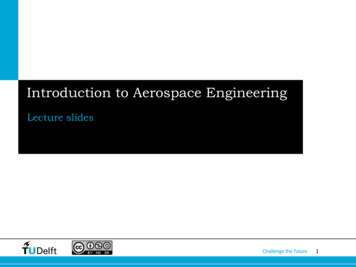
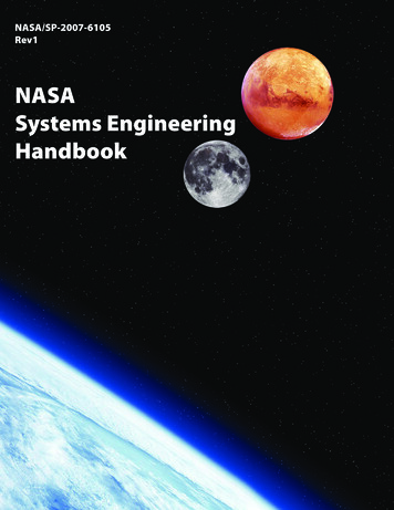
Journal of Technology and Science Education - http://dx.doi.org/10.3926/jotse.26They are also able to become acquainted with other students and learn about other research projects that areto be conducted during the flight week. Teams participate in a Test Readiness Review, where they brief NASAflight directors on their experiment and ensure that it is both ready and safe to fly. The flights then occur at theend of the week, and teams that are not flying on a certain day may be escorted around the Johnson SpaceCenter for tours at different facilities.Each experiment is tested in the course of two flights, which take place in different days. Only six members ofeach team, composed by the faculty advisor, the NASA Principal Investigator and four students, can participatein the flights, three at a time. Teams are allotted a section of the cabin space to place their experiment andcarry out the research. Many flight crew personnel join the flights in order to ensure nobody is injured or ill andassist with any research activities if requested. Camera crews are also present in flights so that all experimentsare well-documented for future publication and outreach. Students are encouraged to take advantage of therare flight opportunity by having fun and performing outreach activities in addition to conducting research.Upon their return to school, teams are encouraged to publicize their own work by creating videos, holdingoutreach events, and conducting interviews with the public media. Students are then required to completepost-flight analysis of their experiment and compose a final report that documents the results of theexperiment: whether the objectives of the experiment were satisfied, lessons learned and recommendations,should a potential future zero gravity campaign the following year be required to complete the experiment.3ZERO GRAVITY AIRCRAFT OPERATIONSThe weightless, or zero gravity environment, is achieved onboard a specially modified Boeing 727-200 providedby the Zero G Corporation (2011), a privately held company acquired by Space Adventures, Ltd.Weightlessness is achieved by doing aerobatic maneuvers known as parabolas (Fig. 1). A typical mission is 2 to3 hours long and consists of 30 to 40 parabolas. These parabolas can be flown in succession or with shortbreaks between maneuvers to reconfigure test equipment. The aircraft flies in a Federal AviationAdministration designated airspace that is approximately 100 miles long and 10 miles wide.Before starting a parabola, the aircraft flies level to the horizon at an altitude of 24,000 feet. The pilots thenbegin to pull up, gradually increasing the angle of the aircraft to about 45 to the horizon reaching an altitudeof 34,000 feet. During this pull-up, passengers will feel the pull of 1.8 Gs (1.8 times the acceleration of gravity).Next, the plane is pushed over to create the zero gravity segment of the parabola. For the next 20-30 secondseverything in the plane is weightless. Then, a gentle pull-out is started which allows the flyers to stabilize onthe aircraft floor. This maneuver is repeated 30 to 40 times, each taking about ten miles of airspace to perform.Fig. 1. Typical zero gravity maneuverThe aircraft is also able to provide during the flight periods of lunar gravity (1/6 of Earth’s gravity) forapproximately 30 seconds, and Martian gravity (1/3 of Earth’s gravity) for approximately 40 seconds (NASA/JSCAircraft Operations, 2011). These gravity forces are created by flying a larger arc over the top of the parabola.Vol. 2(1), 2012, pp 6
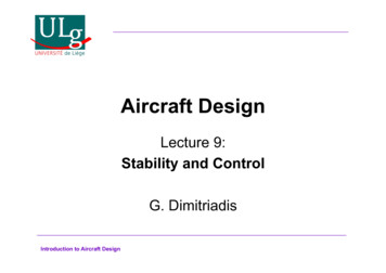
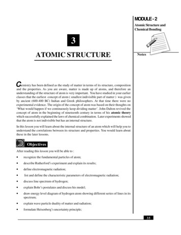
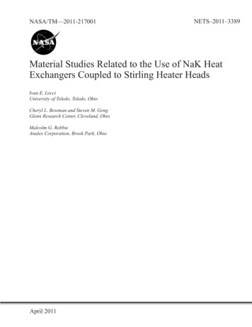
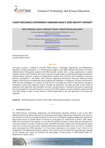
Journal of Technology and Science Education - http://dx.doi.org/10.3926/jotse.264FLIGHT MECHANICS EXPERIMENTA group of undergraduate students from California State Polytechnic University, Pomona, worked incollaboration with their NASA Principal Investigator (the third author of this paper) on a project entitled“Emergency Atmospheric Entry with Control in One Axis” (AECOX), (Matthews et al., 2011). The goal of theexperiment was to prove an innovative control method, primarily conceived as an emergency backup system,which addresses the problem of a capsule-type spacecraft in space that needs to execute a safe atmosphericentry in an emergency situation in the absence of nominal control capability and where the spacecraft is at anarbitrary initial orientation (also referred to as “attitude”) and angular rate.To prove this control method, the students designed and built two test apparatus. They chose, integrated andtested the instrumentation they deemed was required to fly the experiment, and designed, developed andtested the internal flight software. They also carried out, together with the NASA Principal Investigator andFaculty Advisor, the experiment onboard the NASA’s zero gravity aircraft.4.1Background of the ExperimentThe location and orientation of the reaction control system (RCS) jets in a manned space capsule is arranged toprovide control in three axes: torques on pitch, yaw, and roll (Fig. 2). Upon completion of the mission, afterseparation from the service module (SM), the RCS maneuvers the capsule to the entry attitude and, duringnominal atmospheric flight, manages the orientation of the capsule’s lift vector to control crossrange anddownrange. In the absence of backup systems, a major malfunction in the nominal RCS after the separationfrom the SM would prevent the capsule from actively recovering from either a possible tumbling or an adverseattitude that could result in a non-heat-shield forward entry that could jeopardize the safety of the crew.In case a software or hardware failure makes it impossible to fly a guided atmospheric entry, the emergencyentry system mode is invoked to fly a ballistic entry. A ballistic entry is solely focused on crew survival. Toachieve a safe ballistic entry, two control phases need to be executed sequentially: First, the spacecraft mustbe oriented such that the heat shield faces the incoming airflow (i.e., in a heat-shield-forward attitude) tocounteract the heat rate buildup, and second, the spacecraft must attain a ballistic roll rate during entry toprevent a lift-vector-down situation that would result in excessive loads on the crew.Fig. 2. Pitch, yaw and roll angles in a capsule-type spacecraftGarcía-Llama and Senent (2008) developed a method, primarily conceived as an emergency backup controlsystem, which enables a space capsule to execute a safe atmospheric entry from an arbitrary initial attitudeand angular rate in the absence of nominal control capability. Specifically, this method permits the arrest of atumbling motion, orientation to the heat shield forward position and the attainment of a ballistic roll rate of arigid capsule with the use of control in one axis only.The goal of the experiment was to prove the proposed control concept using two test articles; each one with adifferent inertia matrix configuration. For the sake of simplicity for this experiment, a reaction wheel was usedto simulate the torque that would be provided by the jets in an actual spacecraft.4.2Test ApparatusTwo test apparatus structures made with aluminum with dimensions 22.9 cm x 22.9 cm x 15.2 cm were createdfor the free floating experiment (Fig. 3). One structure was built to test an axis symmetrical inertia matrixVol. 2(1), 2012, pp 7
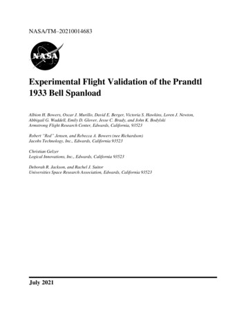
Journal of Technology and Science Education - http://dx.doi.org/10.3926/jotse.26design while the second structure was built to test a diagonal non-axis symmetric inertia matrix design. Bothstructures were the same in design with the structure and components; however, the diagonal non-axissymmetric design used weights to offset the moments of inertia.The internal parts of the test apparatus consisted of a brushless motor, motor flywheel, batteries, avionics,electronic speed controller, and two project boxes, which enclosed the avionics and the speed controller. Allthe internal components were enclosed within the test structure through the means of Lexan sheets, whichwere fastened to the exterior of the structure to form the walls of the structural test apparatus. An acrylicsheet was attached to the center of the test apparatus to create a shelf-like surface for placement of internalcomponents. All internal components, covers, and structures were fastened to each other through the use ofmachine screws and lock washers, thus preventing parts from coming loose due to vibrations emanating fromthe motor and flywheel during testing. Foam corners were also utilized in the structure by placing them on thecorner beams to ensure safe handling for the structure itself and any passengers on the flight, if the freefloating test apparatus were to become a projectile.Fig. 3. Complete assembly of the test apparatus with all internal components4.3Experiment DescriptionBefore flight on board the Reduced Gravity Aircraft, the aircraft was loaded with the two test articles, acamera, a notebook computer, and the outreach items. Velcro and duct tape were used to secure thenotebook computer to the floor of the aircraft.Four foot straps (Fig. 4) were obtained and mounted to the floor of the aircraft to ensure physical security andmobility during the microgravity portion of the flight. Once the apparatus was fully prepared for flight, thecomputer, test articles and the camera were stored in the available storage containers provided by theReduced Gravity Office.Fig. 4. Installation of foot strapsOnce the plane was airborne and it was safe to maneuver inside the cabin, the team set up the neededinstrumentation for the experiment. This included mounting the notebook computer to the aircraft, turning onthe computer, and opening all of the needed software programs and user interfaces for commanding theVol. 2(1), 2012, pp 8
Journal of Technology and Science Education - http://dx.doi.org/10.3926/jotse.26electronics. Three initial tests were conducted to verify operational ability of electronic components and toconfirm the functional use of the reaction wheel.As stated above, two test articles simulating two spacecraft with different inertia configurations were tested inthe experiment, each on different flight days (Fig. 5). One test article simulating a spacecraft with anaxisymmetric inertia matrix was tested on the first flight day whereas the other, simulating a spacecraft with adiagonal non-axisymmetric inertia matrix, was tested on the second flight day. Each had a reaction wheelmounted at the center of gravity that provided torque along the longitudinal axis. On each flight day, beforeeach parabola, the corresponding test article was placed in an arbitrary orientation simulating the heat shieldforward position with the longitudinal axis aligned with the simulated velocity vector. Once in that orientation,the attitude on board was reset to zero in all axes. That became the reference attitude for the remaining of theexperiment during that parabola. After this operation took place, the test article was manually induced with atumbling motion during the zero-g periods. Following the commands from the control law, the reaction wheelgenerated torques aimed at stabilizing the test article at a selected total angle of attack (angular distancebetween the longitudinal axis and the direction of the simulated velocity vector) simulating the heat shieldforward position, at the same time that an angular rate was generated about the longitudinal axis of the testarticle, simulating a ballistic roll rate.Fig. 5. Release of the test apparatus inside the cabin during a zero-g period5RESULTS AND LESSONS LEARNEDSome aspects of the concept of the project were relatively similar to previous experiments the team hadconducted in a prior experience. Thus, the conceptual approach in terms of building the test articles wasfamiliar, and the team had studied related aspects in their course learning as well. However, the team stilllacked the amount of expertise needed for such a complex project; as a result, the team encountered manydifficulties especially interfacing the electronic hardware and yielding the desired outputs from their avionicssystem (Matthews et al., 2011).5.1ResultsUpon reviewing the data from both test flights, it was determined that the obtained data could not be used toreach a conclusion that could validate or invalidate the hypothesis of the experiment. Although, during flight,some of the experiments visually seemed to be successful (the spacecraft would tumble and then precess andstabilize about one axis), the data obtained did not display any similar patterns in comparison to the theoreticalresults, which were generated through a dynamical model developed in the MATLAB and Simulink softwareengineering tools. Also, during the second flight day, while testing the test article with the diagonal nonaxisymmetric inertia matrix, the signals were not being transferred correctly inside the apparatus. During thefirst four tests of the second day, after the article was released, there was no motor rotation. At that time, itwas concluded that this behavior was due to a program flow error. Once it was determined that this test articlewas not compliant, the test articles were quickly switched and the one with the axisymmetric inertia matrixwas tested again.Vol. 2(1), 2012, pp 9
Journal of Technology and Science Education - http://dx.doi.org/10.3926/jotse.265.2Lessons Learned and RecommendationsA huge component that hindered the outcome and success of the project was the lack of experience on theteam. The electrical team in particular had only previously started operating with electronics (microcontrollers,sensors, etc.) and had not yet fully developed the knowledge required to interface these electronics togetherinto a complete system. The team heavily relied on peers from the Electrical and Computer Engineeringdepartment for help or advice. Improvements can be made by having a more interdisciplinary team that hasthe proper training and background to sufficiently accomplish the goals of the project. A future microgravityteam will be accommodating more Electrical/Computer Engineers for this purpose.Physical application of the control torque was performed via a brushed R/C car motor in conjunction with analuminum flywheel. Many of the difficulties arose due to the unrepeatability performance of the motors. Theoriginal (first choice) motor was brushless and it was anticipated that the velocity of the output of the motorwould be a linear function of the applied voltage. However, after extensive testing, it was found that the motorwas operating on a step output of velocity and was not feasible for adaptation for the project. This led to thedecision to switch to a brushed motor setup, which ultimately provided the expected relative linear nature ofvelocity output with voltage, but most importantly, more accurate and repeatable results. For future projects,the team plans to look into stepper motors, as they may provide for an even more accurate rotation.Another problem was correcting for gyroscopic drift. For the future, greater expertise in this area is required,because the sensor plays a vital role in the overall objective and scope of the project. Monetary constraintsprevented the purchase of higher quality sensors. For future projects, the team plans to invest in better sensorsproviding the funding is available.A general unfamiliarity of integrating gyroscopes into a system compounded the previously mentionedproblem, resulting in a position error of up to 10 degrees. Also, during the actual test, the gyroscopes did notinitialize correctly and thus the angular rates and angles were incorrect. The angular rates are key inputs for thecontrol law and error in the angular rates caused an error in the output of the control law. From this, the teamlearned that integrating components to yield a fully functioning system is much more difficult than expectedand there are many factors that need to be accounted for when attempting to correct for gyro drift.Typically, when the program is initialized, the onboard gyroscopes record an initial reading for calibration incase any background noise is present. However, during tests, the gyros had issues initializing and werereporting movement when the test article was not in motion. This was observed when the angular rates werestreamed to the laptop prior to the actual test. This resulted in inaccurate angular readings that adverselyaffected the remainder of the data calculated using the angular rates.Due to an algorithm error, the angular position was not reset after each test, causing the angular positions toaccumulate after each conducted test. To remedy this issue, the test article was reset after each test using thekill switch installed onboard. Typically, this would not be an issue except for the aforementioned initializationerror. This error indicated that the gyros could be initialized incorrectly each time the system was reset, whichdramatically increased the likelihood of error in the system.In addition, for future research the team plans to integrate a gyro filter that will help rid the system gyroscopesignal noise. This was attempted during the time span the team had to work on the project, but because oftime constraints, the team was unable to complete the filter and integrate it into the system. This task will beone of the most important for the new and upcoming team.Another improvement the team plans to make is the addition of a sensor that will read the actual angularvelocity of the reaction wheel. The system, as it is now, is commanding the reaction wheel to rotate at a certainvelocity without measuring the actual rotational velocity, accepting the theoretical value. Time constraintsprevented the team from implementing a speed sensor. The addition of the sensor would allow for the team toperform more precise data analysis. The more known factors of the system the easier it is to troubleshoot. Thiswill also show the team if the signal commanded by the control law was being implemented and sentsuccessfully to the motor.While analyzing the data, it was noticed that some of the calculated angles were diverging. It was determinedthat using Euler angles resulted in singularities for certain values. These singularities resulted in dramaticchanges to the system. This error can be alleviated, but it requires changing the orientation system from Eulerangles to quaternions or direct cosine matrices (any system that does not suffer from singularities). This will belooked at in future projects.Vol. 2(1), 2012, pp 10
Journal of Technology and Science Education - http://dx.doi.org/10.3926/jotse.26Finally, while analyzing why the non-axisymmetric code failed to produce any results, there was no solidconclusion. There does not appear to be any significant differences between how the two codes handle thecontrol law, however, the microcontroller appears to fail while calculating the required acceleration. It wasconcluded that if the needed mathematical calculations are too complex, the microcontroller is unable toprocess further calculations, becoming “stuck” on a certain number. It is not fully understood why thishappens, but it is recommended for future projects to acquire better microcontrollers for complex algorithms(such as a PIC microcontroller). Despite choosing the Ariduno microcontroller for this project (because of it isease-of-use), it did not seem to be designed for heavy calculations, such as the ones involved in this project.The last and probably most prominent obstacle the team encountered was simply the lack of time needed tocomplete the project. The lack of experience required greater time for research and ground testing of the finalfully assembled test articles prior to flight. Such a complex system requires more than ten weeks to fullycomplete, considering the class requirements and work load each student had while working on the project.Many projects that are tested in microgravity are continuations of projects worked previously by otherstudents, while this project had very little references from which it could build a solid foundation. Had theprogram provided a few more months, more would have been accomplished.6CONCLUSIONNASA’s Microgravity Program provides students with the opportunity to engage in STEM-related activities tolearn valuable lessons in teamwork and gain real hands-on experience with challenging projects. These uniqueand thrilling activities can be used to motivate younger students and stir interest in science and engineering inthe classroom. The SEED program in particular allowed for a complete systems engineering approach to gain aholistic perspective of a complex system and encouraged the employment of management, organization, andcommunication skills with an interdisciplinary team to design and fabricate a project. Students at the CaliforniaState Polytechnic University, Pomona, were able to extract valuable lessons in teamwork and systemsengineering through the SEED program that will prepare them for real-world applications and help inspireothers to pursue similar careers in STEM fields.Upon the completion of this experiment, the team gained experience not only in the technical realm but also incommunications, innovation, time management and leadership areas. Each of the students that worked on thisproject also gained valuable experience in space flight mechanics that will be very useful both in school andfuture career opportunities. Starting from scratch, learning the mechanics, and being able to develop aprototype spacecraft allowed f
flight mechanics experiment onboard nasa’s zero gravity aircraft Kyle R. Matthews 1 , Samira A. Motiwala 1 , Donald L. Edberg 2 , Eduardo García-Llama 3 1 Aerospace Engine