Transcription
NASA/TM–20210014683Experimental Flight Validation of the Prandtl1933 Bell SpanloadAlbion H. Bowers, Oscar J. Murillo, David E. Berger, Victoria S. Hawkins, Loren J. Newton,Abbigail G. Waddell, Emily D. Glover, Jesse C. Brady, and John K. BodylskiArmstrong Flight Research Center, Edwards, California, 93523Robert “Red” Jensen, and Rebecca A. Bowers (nee Richardson)Jacobs Technology, Inc., Edwards, California 93523Christian GelzerLogical Innovations, Inc., Edwards, California 93523Deborah R. Jackson, and Rachel J. SuitorUniversities Space Research Association, Edwards, California 93523July 2021
NASA STI Program Report SeriesThe NASA STI Program collects, organizes, providesfor archiving, and disseminates NASA’s STI. TheNASA STI program provides access to the NTRSRegistered and its public interface, the NASATechnical Reports Server, thus providing one of thelargest collections of aeronautical and space scienceSTI in the world. Results are published in both nonNASA channels and by NASA in the NASA STIReport Series, which includes the following reporttypes: TECHNICAL PUBLICATION. Reports ofcompleted research or a major significant phase ofresearch that present the results of NASAPrograms and include extensive data or theoreticalanalysis. Includes compilations of significant scientific and technical dataand information deemed to be of continuingreference value. NASA counter-part of peerreviewed formal professional papers but has lessstringent limitations on manuscript length andextent of graphic presentations.TECHNICAL MEMORANDUM.Scientific and technical findings that arepreliminary or of specialized interest,e.g., quick release reports, workingpapers, and bibliographies that contain minimalannotation. Does not contain extensive analysis.CONTRACTOR REPORT. Scientific andtechnical findings by NASA-sponsoredcontractors and grantees. CONFERENCE PUBLICATION.Collected papers from scientific and technicalconferences, symposia, seminars, or othermeetings sponsored orco-sponsored by NASA. SPECIAL PUBLICATION. Scientific,technical, or historical information from NASAprograms, projects, and missions, oftenconcerned with subjects having substantialpublic interest. TECHNICAL TRANSLATION.English-language translations of foreignscientific and technical material pertinent toNASA’s mission.Specialized services also include organizingand publishing research results, distributingspecialized research announcements and feeds,providing information desk and personal searchsupport, and enabling data exchange services.For more information about the NASA STI program,see the following: Access the NASA STI program home page athttp://www.sti.nasa.gov Help desk contact orm/and select the “General” help request type.
NASA/TM–20210014683Experimental Flight Validation of the Prandtl1933 Bell SpanloadAlbion H. Bowers, Oscar J. Murillo, David E. Berger, Victoria S. Hawkins, Loren J. Newton,Abbigail G. Waddell, Emily D. Glover, Jesse C. Brady, and John K. BodylskiArmstrong Flight Research Center, Edwards, California, 93523Robert “Red” Jensen, and Rebecca A. Bowers (nee Richardson)Jacobs Technology, Inc., Edwards, California 93523Christian GelzerLogical Innovations, Inc., Edwards, California 93523Deborah R. Jackson, and Rachel J. SuitorUniversities Space Research Association, Edwards, California 93523National Aeronautics andSpace AdministrationArmstrong Flight Research CenterEdwards, CA 93523-0273July 2021
AcknowledgmentsMany people contributed directly to this work through their ideas, comments, suggestions, andassistance. The authors concede that many people are likely inadvertently omitted from the list below, andwe express our apologies for any collective failures of memory. Our thanks to:Derek Abramson, Chris Acuff, Jonathan Adams, Mike Agnew, Keenan Albee, Estela Bragado Aldana,Mike Allen, Luis Andrade, Sipanah Arutyunyan, Erin Askins, Dan Banks, Leo Banuelos, Josh Barrett,Sam Batarseh, Ryan Beattie, Nathan Bell, Dave Berger, Blake Berk, Robert Bloom, John Bodylski,Nathaniel Boisjolie-Gair, Olivia Bosma, Jason Bowen, Jesse Brady, Connor Bray, Jerry Budd, AndrewBurrell, Michael Butros, Dennis Calaba, Kimmie Calahan, Brent Cano, Donna Cedana, Johncarlo Cerna,Alex Chen, Kai Creason, Ethan Czuppa, Paul Dees, John Del Frate, Bryce Doerr, Ryan Dunphy, DanteDuran, Louis Edelman, Noah Edwards, Ana Escalera, Cynthia Farr, Nick Farrell, David Faust, KirstenFogg, Mike Frederick, Tomoki Fukazawa, Christian Gelzer, Katherine Glasheen, Scott Gleason, EmilyGlover, Kevin Guerra, Jacob Gustafson, Eric Gutierrez, Etan Halberg, Justin Hall, Lydia Hantsche, AdamHarding, Stephen Harris, Ross Hathaway, Victoria Hawkins, Kira Headrick, Zack Hewitt, Bob Hoey,Brendan Holland, Sanel Horozovic, Reimar Horten, Walter Horten, Richard M. Howard, Lauren Hughes,Samantha Hull, Deborah Jackson, Chris Jensen, Jack Jensen, Taylor Jensen, Kristyn Kadala, CodyKarcher, Koen vander Kerckhove, Mike Kerho, Elizabeth Kissling, Emma Kleiner, David Kloesel, KurtKloesel, Michael Kloesel, Macie Kowalski, Brian Kramer, Heather Laffoon, Kyle Lanni, James Larson,Cameron Law, Joyce Le, Mandy Ledford, David Lee, Russell Lee, Jack Levine, Jay Levine, Caleb Lloyd,Victor Loera, Arlene Lopez, Joe Lorenzetti, Brooke Losey, Kyle Lukacovic, Paul MacCready, JustineMack, Anthony MacPherson, Jose Manriquez, Mike Marston, Walker Martin, Ben Martins, KassidyMcLaughlin, Orlando Mielke, Chris Miller, Stephen Moes, Matt Moholt, Lesli Monforton, WilliamMorris, Rick Motalwakel, Jim Murray, Hussein Nasr, Emma Neal, Loren Newton, Golda Nguyen,Gunhilde Horten Nickel, Karl Nickel, Eric Nisbet, Alexandra Ocasio, Dennis Olcott, Gary Osoba, JoePahle, Steve Parcel, Allen Parker, Kurt Pauer, Frank Pena, Shelby Pfeifer, Nancy Pinon, JosephPiotrowski, Brian Plank, Ariel Prabawa, Bogdan Pugach, Andy Putch, Ronalynn Ramos, NalinRatnayake, Chris Regan, Nickelle Reid, Terry Reilly, Stephanie Reynolds, Rebecca Richardson, JeromyRobbins, Amanda Roberts, Javier Rocha, Emma Ruano, Victor Ruiz, Aamod Samuel, Barkha Scherp,Peter Selinger, Jaiwon Shin, Alec Sim, Patrick Sosa, Amada Spakes, Reinhold Stadler, MarkoStamenovic, Alex Stuber, Curtis Stump, Rachel Suitor, Kaitlyn Summey, Ed Swan, Chante Swart, JoshTanon, Brian Taylor, Carla Thomas, Jack Toth, Tom Tschida, Edward Uden, Julianna Plumb Ulrich,Eduardo Uribe-Saldana, Moiz Vahora, Felipe Valdez, Christos Valiotis, Lynn Valkov, Steffi Valkov,David Voracek, Abbigail Waddell, Joey Wagster, Megan Waller, Kaixi Wang, Shelby Worrell, ChristineYang, Hovig Yaralian, Seung “Paul” Yoo, Ivo Zell, and Jonathan Zur.Trade names and trademarks are used in this report for identification only. Their usage does not constitutean official endorsement, either expressed or implied, by the National Aeronautics and SpaceAdministration.This report is available in electronic form athttp://sti.nasa.gov
AbstractThis report describes the validation of the 1933 Prandtl bell spanload. This spanload is the minimuminduced drag of a wing for a given structural weight with properties that eliminate adverse yaw. Aircraftusing the Prandtl bell spanload were flown and investigated. The results of this research show that manypreviously held assumptions should be rethought, and the creation of aircraft using the Prandtl bellspanload will require considerable new techniques.Part of this work centered on the use of inverse methods. The usual first-step approach to acomputational fluids problem is to create a geometry of the aircraft. Once this geometry exists, thecomputational fluids solution has been solved; however, the problem of creating the geometry still exists.A very small segment of the computational fluids world has concentrated on inverse solutions. Thisdesign approach begins with an end result - the computational fluids solution; from this end result, thegeometry is sought.A more generic inverse tool was desired that would allow for the design of wings - specificallyPrandtl bell spanload wings. Such a tool has been developed and allows for variable taper, aspect ratio,sweep, airfoils, and design-lift coefficients; output from the tool results in twist distribution of RPMUASXC2D3DCDCLCmCnδaCpαangle of attackcenter of gravitydownwashelevator c pressure measurementFiber Optic Sensing Systemlift/dragmean aerodynamic chordminimum induced lossroot mean squarerevolutions per minuteunmanned aircraft systemschord t of dragcoefficient of liftcoefficient of pitch momentcoefficient of yawing moment as a function of delta aileron deflectioncoefficient of pressureangle of attack1
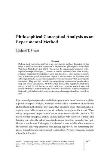
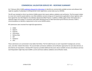
IntroductionOn June 22, 1918 the esteemed professor Ludwig Prandtl stood before his students and began aderivation on the blackboard. His students took notes and two of them, Max Munk and Albert Betz, paidspecial attention. Prandtl had developed his lifting-line theory and was explaining his idea to his students.Prandtl would later translate these works into English; these works were published in 1918 (ref. 1) and1919 (ref. 2).Prandtl’s lifting-line theory proposed that the lift of a wing can be formulated as equivalent to thecirculation around a line. This became the first analytical tool by which the lift of a wing could becalculated. The tool also enables the estimation of the load experienced by the wing, allows for arbitraryplanforms, arbitrary twist, and control surface deflections. Prandtl then extended the idea to calculate theminimum induced drag for a wing of a given wingspan. Prandtl showed this value to be the ellipticalspanload (ref. 3), as shown in figure 1. In Prandtl’s 1921 elliptical spanload is shown the extension of theelliptical spanload to the optimization of the propeller by Betz (see ref. 3). An extension of Prandtl’s work(ref. 4) allows for the effects of multiple wings.Figure 1. The 1921 Prandtl elliptical spanload.Both the 1921 spanload by Prandtl and the 1921 propeller formulation by Betz were established usingthe wing span or the propeller diameter as constraints. In 1933 Prandtl created a newly optimizedspanload (ref. 5). The new spanload is not elliptical and discards the span constraint. In its place is astructural constraint of holding constant the integrated root-bending moment of the wing. Figure 2 showsa comparison of the lift and downwash span distribution of the elliptical and bell spanloads with theirrespective integrated wing-root bending-moment held constant at the same value. The new spanload(which we refer to as being bell-shaped) has 22.5-percent more span and 11.9-percent less induced dragthan the equivalent elliptical spanload. Recall that the elliptical spanload was presented by Prandtl in 1921and produced the minimum induced drag for a given wing span. The bell spanload was presented byPrandtl in 1933 and produced the minimum induced drag for a given total structural weight of the wing.When comparing Prandtl’s two minimum drag solutions, it is important to remember the specificconstraints that resulted in each one. The 1921 solution yields a minimum drag for a given wing span.The 1933 solution yields a minimum drag for a given weight of wing spar. By holding the mass of the2
wing structure (the wing spar) constant, the span increases as the load near the wing tip is decreased tomaintain the constant weight of the wing structure which has the effect of increasing the aspect ratio,therefore reducing the induced drag. The decrease in load near the wing tip has the effect of reducing thespan efficiency which increases the induced drag. In the balance between these two effects the increase inthe wingspan dominates, resulting in a net decrease in the induced drag.Figure 2. The Prandtl elliptical spanload (curve a) compared to the Prandtl bell-shaped spanload (curve b).Other researchers have proposed alternative bell-shaped spanloads using differing constraintscompared to Prandtl’s bell solution. Starting in about 1935 the Horten brothers (refs. 6-8) designed andconstructed a series of increasingly higher-performance sailplanes, and other aircraft, in a pursuit ofproverse yaw (ref. 9) flight mechanics solutions. Ultimately, on the cusp of the discovery of the solutionof this flight mechanics problem, Reimar Horten ceased his life’s work in 1954, leaving the solutionunproven. Horten never entered into the solution of the induced-drag problem. In 1950, researcher RobertT. Jones of the National Advisory Committee for Aeronautics (NACA) created a spanload that used thewing-root bending moment as a structural constraint (ref. 10) and found a related solution to that of thePrandtl bell spanload. Jones showed a 26-percent gain in span with a 17-percent reduction in induced drag(but allowed an unspecified small increase in structural weight). Finally, in 1975 the two researchersArmin Klein and Sathy Viswanathan (ref. 11) extended Prandtl’s bell spanload by adding an additionalconstraint that used the shear of the wing (holding the integrated shear of the elliptical and bell spanloadsconstant). Klein and Viswanathan found that a 17-percent increase in span resulted in an 8-percentreduction in induced drag. This line of thought appears to end here and results in the refrain of Prandtl,Horten, Jones, and Klein and Viswanathan as the line of spanload researchers. Robert T. Jones (ref. 12)and Ilan Kroo (ref. 13) published collections of these differing thoughts, yet neither of them includedHorten, indicating Horten’s lack of tackling induced drag.The solution to the spanload problem that solves the discrepancy between the flight of nearly allmodern aircraft and the flight of birds affirms Horten's relevance to Prandtl, Jones, and Klein andViswanathan. Only through the connection between the proverse yaw flight mechanics solution to the3
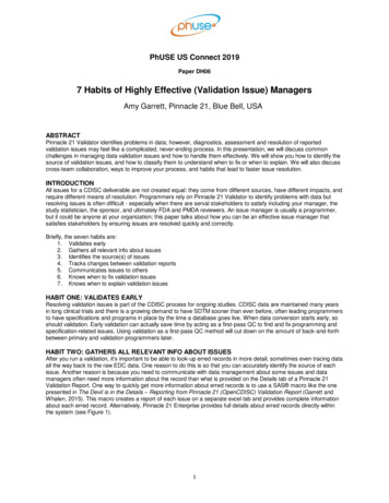
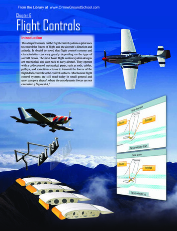
adverse yaw problem and the minimum induced drag with the structural constraint solution, can one solvethe bird flight spanload problem.We selected the Prandtl solution for two reasons: one analytical and the other anecdotal (see ref. 9).The analytical reason is the formulation of the Breguet Range Equation (ref. 14) which shows that therange of an aircraft is equal to the propulsive efficiency multiplied by the aerodynamic efficiency,multiplied by the log of the quotient of take-off gross weight and landing weight (most of the landingweight is the structural weight) and then multiplied by a constant (to make the units work out correctly).Of note is the aerodynamic efficiency divided by the log of the landing (structural) weight. Kuchemannmakes note of this solution (ref. 15), yet Kuchemann does not reference Breguet. This lack is oneargument in favor of both Prandtl bell, and Klein and Viswanathan, solving for both induced drag andminimum structure. Anecdotal evidence would show that aircraft wings fail in bending and do notnormally fail in shear. This argument favors the Prandtl bell and Jones spanload solutions, solving forboth minimum induced drag and wing bending moment. The overlap between these two sets is the Prandtlbell-shaped lift distribution.The downwash equation for the Prandtl bell-shaped lift distribution is a smooth, continuous function.Mathematically, a smooth continuous function is desirable because it eases manipulation. Singularities(points at which the mathematics go to infinity or degenerate (the equation does not produce an answer))are intractable. The downwash calculation for the elliptical wing produces singularities at the wingtips, asshown in figure 3(a). Singularities exist in neither the spanload nor the downwash calculations for thePrandtl bell spanload, as shown in figure 3(b).Figure 3. (a) The 1921 Prandtl elliptical spanload, with singularities (the upwash values approach infinityas the flow approaches the wingtips); and (b) the 1933 Prandtl bell-shaped spanload, with no singularitiesin the upwash/downwash flow field.The increased complexity of the flow field demands an expanded definition to properly describe theflow around these wings. The classical elliptical wing is simple: the upwash (and the resulting downwash)is constant across the entire wing. A simple summation of the upwash and downwash thus could be madeat any point along the wing, with the result always valid simply because the elliptical spanload producescompletely uniform upwash and downwash across the entire wing. The Prandtl bell-shaped spanload,however, does not behave in this manner: it is a completely three-dimensional (3D) flow field solution.The result is that a simple solution no longer suffices; it is necessary to integrate the solution across theentire span of the wing to properly evaluate the total net downwash behind these wings.“Wash” is the generic term for both upwash and downwash. Upwash is defined as a positive value;downwash is defined as a negative value, as shown in figure 4. The local upwash/downwash is the flowangle resulting from the immediate upwash or downwash at or near the leading- or trailing-edge across4
the chord at a given span. The net upwash/downwash is the sum of the local upwash and local downwashacross the chord at a given chord (or at a particular spanwise) location, as shown in equation (1). The totalupwash or total downwash is the integrated value of the net upwash and the net downwash across theentire span of the wing, as shown in equation (2).Net upwash/downwash at a particular span location [Local upwash Local downwash](1)Total upwash or downwash Net upwash downwash(2)Figure 4. Local downwash, local upwash definition, and net upwash/downwash at a particular chord(spanwise location).Prandtl’s original formulation of the 1921 elliptical spanload was made in the following way. Thesolution is inviscid, so the effects of Reynolds number do not apply in the lifting-line formulation. Thewing is assumed to be flat and is treated as a thin airfoil with no camber. The local upwash and the localdownwash are the same for the entire span, the local downwash being of greater magnitude than the localupwash. Thus, the total effect of the wing is that the wing creates a net total downwash. In effect, thesolution for the 1921 Prandtl elliptical spanload is that the flow is always a two-dimensional (2D)solution. The local lift coefficient is exactly identical at every point along the span, the local upwash isexactly identical at every point along the span, the local downwash is exactly identical at every pointalong the span, and the net downwash is exactly identical at every point along the span.5
Contrast the 1933 Prandtl bell-shaped spanload. At the center, the local downwash overwhelms thelocal upwash; as a result, a net downwash exists at the centerline. This condition exists from thecenterline out to the 70.7-percent span location, where the local upwash and the local downwash areequal, so the net downwash/upwash is zero. Outboard of the 70.7-percent span location, the local upwashis greater than the local downwash, so a net upwash exists all the way out to the wingtip. An integrationof the net downwash/upwash curve will show a total downwash overall. In comparing the 1921 ellipticalspanload total downwash to the 1933 Prandtl bell-shaped spanload total downwash, the induced drag isless for the bell-shaped spanload by 11.87 percent, compared to the elliptical-spanload induced drag.The development of the elliptical spanload was created in the following way. The wing planform iselliptical, there is no twist, and the upwash is uniform along the entire leading edge. The downwash isuniform along the entire trailing edge. At every angle of attack (all of those angles that do not haveseparation anywhere on the wing) the wing will generate a constant net downwash everywhere behind thewing. Thus, the spanload is always elliptical. This approach led to the creation of the elliptical spanload.Effectively, the elliptical spanload is an imposed 2D solution onto the 3D wing.This formulation fails very close to the wingtip. The real viscous fluid prevents the upwash fromsimply going to infinity, and the fluid simply creates an irrotational core to the vortex that shortcuts thedownwash line to upwash curve across the wingtip. This irrotational core causes disruption in the airfoilflow, and the corresponding pressure distributions will not match the 2D solutions that panel methods orEuler solutions generate. Only full Navier-Stokes solutions have any hope of accurately capturing theflow fields and the airfoil pressure distributions near the wingtips.The Betz formulation of minimum induced loss (MIL) for propellers is similar to the formulation ofthe elliptical spanload by Prandtl and Munk. Betz calculated the constant “inwash” for the propellerthrough the actuator disk. If you treat the propeller blade as a wing, inwash is the airfoil downwash. Witha constant inwash, the upwash was held constant across the entire span of the propeller blade. Thedownwash was held constant as well. This condition dictated that the lift coefficient was held constanteverywhere; the angle of attack was held constant along the entire blade span as well. The result is thatthe blade describes an almost perfect cut through the fluid with a constant angle of “slip” at all pointsalong the blade.It is necessary to use twist to create the Prandtl bell-shaped spanload. The twist is not a scalarquantity, it is a vector, and has both a direction and a variation in magnitude along the span. Prandtl’s1933 paper states that the spanload can be achieved using planform “rather the lift distribution of asharp-tipped wing”. The twist is necessary because of the twisted airflow across the span of the wing. Theflow distribution is truly a 3D solution.An analogy description used is a boat on a lake. Imagine a glass-smooth lake and a powerboat sittingon the lake. As the powerboat begins to move forward, a bow wave is formed. The bow wave rises abovethe level of the lake water. The powerboat is not directly pushing the water up, forming the bow wave, butis pushing the water down beneath the hull. The pressure disturbance in the water, caused by thepowerboat, is creating the bow wave. Imagine two surfboards are surfing on the bow wave; bothsurfboards are moving forward at the same velocity as the boat. Now outriggers are added to connect thesurfboards to the boat, and the surfboards are placed such that they are helping to push the boat forward alittle bit. This description is a direct analogy for the Prandtl 1933 bell-shaped spanload solution.(Additionally, we can now steer the powerboat by pushing the bow of the powerboat boat to the left andto the right using the surfboards.)DiscussionA small research project was built around the Prandtl bell solution. Four series of aircraft haveresulted: three small unmanned aerial vehicle (UAV) series and a larger piloted aircraft. The small UAVswere created for the original flight mechanics investigation (those vehicles were called the Prandtl-D1glider and the Prandtl-D2 glider, starting in 2011); the aerodynamics investigation (these vehicles werecalled the called Prandtl-D3 and the Prandtl-D3c, starting in 2014); and the Mars glider application (that6
vehicle was called the Preliminary Research Aerodynamic Design to Land on Mars, or Prandtl-M). Thereexists, as well, the large glider called Prandtl 4.Part of the development of this work involved the use of inverse methods. The usual approach to thecomputational fluids problem is to create a geometry of the aircraft. Once this geometry exists, thecomputational fluids solution can be found; however, this leaves the challenge of creating the geometry.Starting in the 1930s and progressing through the 1980s, a very small segment of the computational fluidsworld concentrated on inverse solutions. This thought process design approach begins with the idea ofwhat the flow must look like in the end. Many selected simplifying assumptions must be made so that themathematical solution to the inverse problem is tractable. The beauty of this approach is that the endpointis the beginning. The difficulty lies in ensuring that the simplifying assumptions do not negate the validityof the final solution.During these years, the forward method iterative approach was used. At the same time, it was knownthere existed an inverse method by which to design wings (see ref. 8). The inverse approach was veryabstract and was only applicable to Horten spanloads. Also known was Horten spanloads and the Prandtlbell-shaped spanload had different constraints and resulted in different spanloads. A more generic inversetool was desired that would allow the design of wings, specifically Prandtl bell-shaped spanload wings.Such a tool was developed and allowed variable taper (or variable chord length distribution), aspect ratio,sweep, airfoils, and design lift coefficients. The output of the tool is the twist distribution; however, thetool can also be inverted easily so that any of the other inputs can be made into the output. The beauty ofthis tool is that the spanload is the initial condition for the wing design. The difficulty is that thesimplifying assumptions (lifting line and thin airfoil) do not negate the final wing solution. This report isthe validation of the Prandtl bell-shaped spanload and this inverse tool.The Prandtl-D1 glider (shown left in figure 5); and the Prandtl-D2 glider (shown right in figure 5)each had a wing span of 12.5 ft wing, a wing area of approximately 10 ft2, and a weight of approximately14 lb. Flight speed was approximately 45 ft/s. These aircraft were instrumented strictly for flightmechanics. There were 12 parameters measured: angle of attack, angle of sideslip, total pressure, staticpressure, pitch rate, roll rate, yaw rate, normal acceleration, axial acceleration, and lateral acceleration,left elevon deflection, and right elevon deflection.Figure 5. (left) The Prandtl-D1 glider in flight; NASA photograph number ED13-0061-39; and (right) thePrandtl-D2 glider in flight; NASA photograph number ED13-0279-54The Prandtl-D3 and Prandtl-D3c gliders each had a wing span of 25 ft, a wing area of approximately40.5 ft2, and a weight between 28 lb and 64 lb. Flight speeds were approximately 26 ft/s to 40 ft/s. Thevariation in weight was due to the particular experiment being flown. The Prandtl-D3 glider, shown on7
the left in figure 6, weighed as little as 28 lb for flight mechanics experiments. The Prandtl-D3c glider,shown on the right in figure 6, weighed approximately 64 lb for the Fiber Optic Sensing System (FOSS)experiments; for the wing pressure experiments the Prandtl-D3c glider weighed approximately 45 lb.Figure 6. (left) The Prandtl-D3 glider in flight; NASA photograph number ED15-0330-079; and (right) thePrandtl-D3c glider in flight; NASA photograph number AFRC2018-0182-34.The Prandtl-D4 glider, shown on the left and right in figure 7, is a piloted single-seat glider with awing span of approximately 50 ft, a wing area of 162 ft2, and weight of approximately 150 lb empty.Figure 7. (left) The Prandtl-D4 glider on the ground; and (right) the Prandtl-D4 glider in flight.The Prandtl-M glider, shown in figure 8, utilizes the research obtained by the Prandtl-D gliders tocreate a glider that is planned to be released in the Martian atmosphere from a 3U CubeSat (CaliforniaPolytechnic State University, San Luis Obispo, California) to fly at Mach 0.5 and collect atmospheric andcartographic data. There are currently two models being tested, called the Prandtl-M (PM) 4.2 and PM5.0. The PM 4.2 has a wing span of 31.25 in, a wing area of 250 in2, and a weight of approximately 0.4 lb.The PM 5.0 has a wing span of 24 in, a wing area of 144 in2, and a weigh of approximately 1.16 lb.8
Figure 8. The Prandtl-M glider in flight.ResultsRecent work falls into three categories: (1) flight mechanics work, as an update to the previous flightmechanics work (see ref. 9); (2) Fiber Optic Sensing System in-flight structural loads to find thespanload; and (3) integrated pressure measurement over the wing to find the spanload. The FOSS fibersand the wing pressures are diagrammed in figures 9(a) and 9(b). Other work included extending theapproach to propellers and fans.9
Figure 9. (a) The Fiber Optic Sensing System fiber installation in the right wing; and (b) wing pressuresand Fiber Optic Sensing System fiber installation in the left wing.Flight MechanicsThe flight mechanics work was continued on the gliders previously described (see ref. 9). As part ofthis work, identical data sets were used by two teams comprised of student interns; independent analyseswere conducted using the same tools and similar, though not identical, techniques (different weightingsfor parameters were selected by each team). The parameter estimation technique used (ref. 16) has beenshown to provide robust and accurate results. Cramer-Rao uncertainties are output as well. The linear fitsshown are based on vortex-lattice (ref. 17) estimates of the control power parameters and estimates fromthose results for the stability and control derivatives for comparison. The two teams each used the inverseof their own uncertainty estimates as weightings for the linear equation fits for the stability and controlparameter for proverse or adverse yaw with aileron deflection. The parameter, Cnδa (coefficient of yawingmoment as a function of delta aileron deflection) is a measure of proverse or adverse yawing moment10
with aileron deflection. A positive Cnδa indicates there is a proverse yawing moment with aileron, that is,the aircraft will roll and yaw in the desired direction as commanded by the pilot. Should the value benegative, there exists an adverse yawing moment with aileron deflection, so the roll and yaw are oppositeto each other and adverse yaw exists. The three results are plotted for comparison in figure 10.Figure 10. Cnδa (coefficient of yaw
constructed a series of increasingly higher-performance sailplanes, and other aircraft, in a pursuit of proverse yaw (ref. 9) flight mechanics solutions. Ultimately, on the cusp of the discovery of the solution of this flight mechanics problem, Reimar Horten cease