Transcription
Simplorer Getting Started GuideANSYS, Inc.Southpointe2600 ANSYS DriveCanonsburg, PA 15317ansysinfo@ansys.comhttp://www.ansys.com(T) 724-746-3304(F) 724-514-9494Release 18.2July 2017ANSYS, Inc. andANSYS Europe,Ltd. are ULregistered ISO9001:2008 companies.
Simplorer Getting Started GuideCopyright and Trademark Information 2017 ANSYS, Inc. Unauthorized use, distribution or duplication is prohibited.ANSYS, ANSYS Workbench, Ansoft, AUTODYN, EKM, Engineering Knowledge Manager, CFX,FLUENT, HFSS and any and all ANSYS, Inc. brand, product, service and feature names, logosand slogans are registered trademarks or trademarks of ANSYS, Inc. or its subsidiaries in theUnited States or other countries. ICEM CFD is a trademark used by ANSYS, Inc. under license.CFX is a trademark of Sony Corporation in Japan. All other brand, product, service and featurenames or trademarks are the property of their respective owners.Disclaimer NoticeTHIS ANSYS SOFTWARE PRODUCT AND PROGRAM DOCUMENTATION INCLUDETRADE SECRETS AND ARE CONFIDENTIAL AND PROPRIETARY PRODUCTS OFANSYS, INC., ITS SUBSIDIARIES, OR LICENSORS. The software products and documentation are furnished by ANSYS, Inc., its subsidiaries, or affiliates under a software licenseagreement that contains provisions concerning non-disclosure, copying, length and nature of use,compliance with exporting laws, warranties, disclaimers, limitations of liability, and remedies, andother provisions. The software products and documentation may be used, disclosed, transferred,or copied only in accordance with the terms and conditions of that software license agreement.ANSYS, Inc. is certified to ISO 9001:2008.U.S. Government RightsFor U.S. Government users, except as specifically granted by the ANSYS, Inc. software licenseagreement, the use, duplication, or disclosure by the United States Government is subject to restrictions stated in the ANSYS, Inc. software license agreement and FAR 12.212 (for non-DODlicenses).Third-Party SoftwareSee the legal information in the product help files for the complete Legal Notice for ANSYS proprietary software and third-party software. If you are unable to access the Legal Notice, please contact ANSYS, Inc.2Simplorer 18.2 - ANSYS, Inc. All rights reserved. - Contains proprietary and confidentialinformation of ANSYS, Inc. and its subsidiaries and affiliates.
Simplorer Getting Started GuideTable of ContentsTable of ContentsContents-11 - Introduction1-1Overview of the Simplorer Interface1-12 - Creating a New Project2-1About the Three-Phase Rectifier2-1Expected Results2-2Using Simplorer to Create and Improve the Design2-3Creating the New Project2-4Add the New Project2-4Rename the Design2-5Add Design Notes (Optional)2-6Save the New Project2-63 - Create the Rectifier Model3-1Create the Three-Phase Rectifier Schematic3-1Choosing, Placing, and Arranging Components on the Schematic Sheet3-2Connecting the Components3-8Defining Component Properties3-8Property Displays for Components3-11Specifying Simulation Outputs3-15Defining Solution Options and Analysis Parameters3-17Starting an Analysis3-18Plotting Rectifier Model Simulation Results3-194 - Hysteresis Current-Controlled DC-Motor Start-UpModify the Rectifier Model Design4-14-1Deleting the Resistive/Inductive Load4-2Saving the Sheet with a New Name4-2Contents-1Simplorer 18.2 - ANSYS, Inc. All rights reserved. - Contains proprietary and confidentialinformation of ANSYS, Inc. and its subsidiaries and affiliates.
Simplorer Getting Started GuideDefining DC Machine Values4-3Defining Mechanical Load4-4Freewheeling Diode4-5Chopper Transistor4-5Controller Modeling Using Block Elements4-7Modifying Report Elements4-9Display Diode Characteristic4-9Defining Simulation Parameters4-11Starting Simulation (Block Components)4-11Simulation Results (Block Components)Controller Modeling Using State Graph Components4-114-12Connecting the State Graph Components4-13Defining the Properties of State Graph Components4-13Using Name References4-16Deactivating Components on the Sheet4-16Starting Simulation (State Graph)4-185 - Current and Speed Controlled DC MotorModify the State Graph Design5-15-1Deleting the State Graph5-2Saving the Sheet with a New Name5-3Defining Mechanical Load (Block)5-4Defining the PI Controller5-6Starting Simulation5-9Adding a Rectangular Plot (PI Controller)5-9Adjusting Plot Properties5-11Checking the Block Sequence5-12Using Automatic Block Sorting5-13Using Manual Block Sorting5-13Contents-2Simplorer 18.2 - ANSYS, Inc. All rights reserved. - Contains proprietary and confidentialinformation of ANSYS, Inc. and its subsidiaries and affiliates.
Simplorer Getting Started GuideRerun the Simulation (PI Controller)5-14Simulation Results (PI Controller)5-146 - Using VHDL-AMS Components for Modeling6-1VHDL-AMS Components6-1Modify the PI Controller Design6-1Save the Project with a New Name6-2Delete the DC Machine Component6-3Placing and Arranging the New VHDL-AMS Components on the Sheet6-3Connecting the New VHDL-AMS Components6-3Defining VHDL-AMS DC Machine Values6-3Defining Connections for Machine Current6-4Defining Simulation Parameters6-5Analyze and Display Simulation Results (VHDL-AMS)6-57 - Variants of PWM Modeling7-1PWM Modeling Overview7-1Create a New Project for the PWM Models7-2Setting Initial Conditions7-2PWM Modeling Using Equations7-3Defining Simulation Parameters7-3Displaying Simulation Results with Reports7-4Simulation Results7-4PWM Modeling with Equations and Time Function7-5PWM Modeling with State Graph Components7-6Place and Arrange the Components on the Sheet7-7Define Component Properties7-7PWM Modeling with Block Diagram Components7-9Placing and Arranging the Components on the Sheet7-98 - Using Legacy Schematics8-1Contents-3Simplorer 18.2 - ANSYS, Inc. All rights reserved. - Contains proprietary and confidentialinformation of ANSYS, Inc. and its subsidiaries and affiliates.
Simplorer Getting Started GuideTranslating a Legacy Schematic using Release 16.2 or Earlier8-2Importing the Legacy Schematic into Simplorer Release 16 or earlier8-2Opening the Translated Schematic in Simplorer 2017.1 or Later8-7Starting an Analysis8-8Plotting Simulation Results8-9IndexIndex-1Contents-4Simplorer 18.2 - ANSYS, Inc. All rights reserved. - Contains proprietary and confidentialinformation of ANSYS, Inc. and its subsidiaries and affiliates.
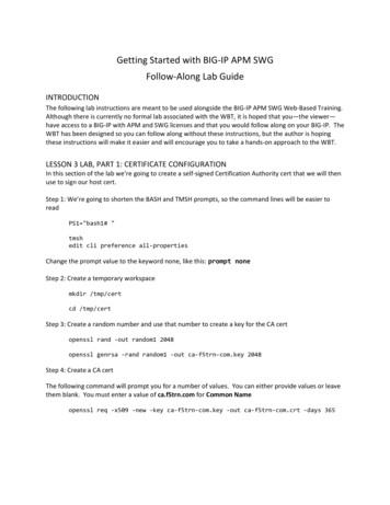
Simplorer Getting Started Guide1 - IntroductionThis Getting Started guide is written for Simplorer beginners as well as experienced users who areusing Simplorer for the first time.Simplorer is a simulation package for multi-domain designs that are commonly found in automotive,aerospace, power electronics, and electric drive systems.Simplorer provides an approach for the virtual prototyping of large-scale systems by letting you todevelop a design that combines predefined basic and industry-specific components with userdefined models. You can create models in common programming languages or standard modelinglanguages such as VHDL-AMS. The basic and industry-specific model libraries available for Simplorer provide ready-to-use parameterized components, making Simplorer accurate, and flexible.lllllllChapter 2 of this guide shows you how to create and save a new Simplorer project.Chapter 3 leads you step-by-step through creating, solving, and analyzing the results of aThree-Phase Rectifier.Chapter 4 modifies the example of Chapter 3 by replacing the resistive/inductive load witha real machine model. The example is then expanded to include a control circuit modeledfirst using discrete components, then using state graph components.In Chapter 5 the state graph controller is replaced with a PI (proportional-integral) controller implemented using block components.Chapter 6 substitutes the use of VHDL-AMS opponents for modeling the DC motor.Chapter 7 explores several different methods for modeling a PWM Controller to demonstrate Simplorer’s versatile modeling capabilities.Chapter 8 leads you through the process of importing a legacy Simplorer 7 Three-PhaseRectifier schematic into Simplorer Release 16.2, saving it, migrating it into Simplorer2017.2, and then solving and analyzing the translated model.Overview of the Simplorer InterfaceBelow is an overview of the major components of the Simplorer interface.Introduction 1-1Simplorer 18.2 - ANSYS, Inc. All rights reserved. - Contains proprietary and confidentialinformation of ANSYS, Inc. and its subsidiaries and affiliates.
Simplorer Getting Started GuideProject Manager window andProject TreeThe Project Manager window shows all the components, models, and other elements of each design in the project. Each project has its own expandable ProjectTree. Many operations on the design elements can be performed directly from theProject Manager window.MessageManagerwindowDisplays error, informational, and warning messages for the active project.ProgresswindowDisplays solution progress information.Introduction 1-2Simplorer 18.2 - ANSYS, Inc. All rights reserved. - Contains proprietary and confidentialinformation of ANSYS, Inc. and its subsidiaries and affiliates.
Simplorer Getting Started GuidePropertieswindowDisplays the attributes of a selected object in the active model, such as the object’sname, electrical or other associated physical quantities, orientation, and color.Also displays information about a selected command that has been carried out.For example, if a circle was drawn, its command information would include thecommand’s name, the circle’s center position coordinates, and the size of itsradius.Design area Displays one or more editor windows such as the Schematic Editor, model editors,windowand symbol editor. It also displays various report windows.Component Displays, on the Components tab, the component categories, including Favorites,LibrariesMost Recently Used, Simplorer Elements, and Project Components. You can pinwindowthe window to make it remain visible or make it visible only when it is being used.The following elements are defined as favorites by default:lR (resistor)lL (inductor)lC (capacitor)lD (diode)lE (voltage source)lAM (ammeter)lVM (voltmeter)The Project Components section lists the elements that are active in your projects.If you have created any personal libraries, a Personal Libraries section displaysthem.The Component Manager window also provides a search feature on the Searchtab.Menu barProvides various menus that enable you to perform Simplorer tasks, such as managing project files, designs, and libraries; customizing desktop components; drawing objects; and setting and modifying project parameters and options.ToolbarsProvides buttons that act as shortcuts for executing various commands.Status barShows current actions and provides instructions.Introduction 1-3Simplorer 18.2 - ANSYS, Inc. All rights reserved. - Contains proprietary and confidentialinformation of ANSYS, Inc. and its subsidiaries and affiliates.
Simplorer Getting Started GuidePDF layout 1-4Simplorer 18.2 - ANSYS, Inc. All rights reserved. - Contains proprietary and confidentialinformation of ANSYS, Inc. and its subsidiaries and affiliates.
Simplorer Getting Started Guide2 - Creating a New ProjectThis guide assumes that you have installed Simplorer.In this chapter you will complete the following tasks:lCreate and save a new project.lAdd and rename a Simplorer design in the project.About the Three-Phase RectifierThe following example describes a three-phase power supply and a rectifier bridge with resistive/inductive load. For the input signals, time-controlled voltage sources will be used. The diodes,the capacitor, and the resistor are ideal components; the diodes are determined by an exponentialfunction (their characteristic).Creating a New Project 2-1Simplorer 18.2 - ANSYS, Inc. All rights reserved. - Contains proprietary and confidentialinformation of ANSYS, Inc. and its subsidiaries and affiliates.
Simplorer Getting Started GuideExpected ResultsAfter the simulation is run, the results are displayed in Report windows. For example, the first simulation variation demonstrates these results:lVoltages of the sources ET1.V, ET2.V, and ET3.VlVoltage of the smoothing capacitor CD.VlCurrent of the load resistor R LOAD.ICreating a New Project 2-2Simplorer 18.2 - ANSYS, Inc. All rights reserved. - Contains proprietary and confidentialinformation of ANSYS, Inc. and its subsidiaries and affiliates.
Simplorer Getting Started GuideUsing Simplorer to Create and Improve the DesignAs you step through this Getting Started guide, you will be introduced to several key concepts:lThere are numerous ways to perform most tasks.For example, several methods are presented for selecting and for assigning design parameter values.Creating a New Project 2-3Simplorer 18.2 - ANSYS, Inc. All rights reserved. - Contains proprietary and confidentialinformation of ANSYS, Inc. and its subsidiaries and affiliates.
Simplorer Getting Started GuidellThere is no required sequence of events when creating a design. — A convenient methodfor creating the three-phase rectifier will be demonstrated, but the design setup steps can becompleted in any logical order.You can quickly modify design properties at any time.For example, you can draw a box freehand, then specify its exact dimensions in the Properties window.lYou can easily manage your design in the project tree.The branches of the project tree in the Project Manager window provide access to setupdialogs, where you can modify design properties.lYou can modify the model view at any time.You will learn shortcut keys like Ctrl D, which fits the model in the view window.lYou can save time by parameterizing design properties.This enables you to quickly modify design properties and generate new results.lYou can use Simplorer’s extensive post-processing features to evaluate solution results.Creating the New ProjectThe first step in using Simplorer to solve a problem is to create a project in which to save all of thedata associated with the problem. A project is a collection of one or more designs saved in a single*.aedt file. By default, opening Simplorer creates a new project named Projectn and inserts a newdesign named Simplorern, where n is the order in which each was added to the current session.Add the New ProjectTo add a new Simplorer project:lClick File New.Creating a New Project 2-4Simplorer 18.2 - ANSYS, Inc. All rights reserved. - Contains proprietary and confidentialinformation of ANSYS, Inc. and its subsidiaries and affiliates.
Simplorer Getting Started GuideA new project named Projectn containing a new design named Simplorern is added in theproject tree in the Project Manager window.HintlllIf the Project Manager does not appear, click View Project Manager.If a new design does not appear automatically, click Tools Options GeneralOptions. Under Project Options, select Insert a design of type.To automatically expand the project tree when an item is added to the project, clickTools Options General Options. Under Project Options, select Expand Project Tree on Insert.The new project contains a file structure that organizes design elements such as: Ports, Analysis, Optimetrics, and Results. Project Definitions such as Components, Symbols, Models,Packages, Materials, and Scripts are also listed.Rename the DesignYou can rename the default Simplorer design name as follows:1. Right-click Simplorern in the project tree, and choose Rename on the shortcut menu. Youcan also click the name to select it, then press F2.This enables the text cursor for the design name.2. Type Rectifier (or some other name of your choosing), and then press Enter to completethe change.Creating a New Project 2-5Simplorer 18.2 - ANSYS, Inc. All rights reserved. - Contains proprietary and confidentialinformation of ANSYS, Inc. and its subsidiaries and affiliates.
Simplorer Getting Started GuideAdd Design Notes (Optional)You can optionally include notes about your design, such as a description of the design beingmodeled, with the project. These notes can be a useful tool for keeping a running log of yourdesigns.To add notes to your design:1. Click Simplorer Circuit Edit Notes.The Design Notes window appears.2. Click in the window and type your notes.3. Click OK to save the notes in the project tree under the current design.Note To edit existing design notes, double-click Notes in the project tree to open theDesign Notes window in which you can edit the notes.Save the New ProjectTo save the new project:1. Click File Save.The Save As dialog box appears.2. Use the file browser to find the directory where you want to save the file.3. Type the desired file name in the File name text box.4. In the Save as type list, ensure that Simplorer Project Files (*.aedt) is chosen. Simplorerproject files are given an .aedt extension by default.5. Click Save to save the project to the specified location.Note For further information on any Simplorer topic, schematic editor commands or windows, you can view Simplorer‘s context-sensitive online help in one of the followingways:Creating a New Project 2-6Simplorer 18.2 - ANSYS, Inc. All rights reserved. - Contains proprietary and confidentialinformation of ANSYS, Inc. and its subsidiaries and affiliates.
Simplorer Getting Started GuidellllClick the Help button in a pop-up window.Press Shift F1. The cursor changes to ?. Click on the item for which youneed help.Press F1 to open the Help window. If you have a dialog box open, the Helpwindow opens to a page that describes that dialog box.Use the commands in the Help menu.Now you are ready to create the Rectifier model.Creating a New Project 2-7Simplorer 18.2 - ANSYS, Inc. All rights reserved. - Contains proprietary and confidentialinformation of ANSYS, Inc. and its subsidiaries and affiliates.
Simplorer Getting Started GuidePDF layout 2-8Simplorer 18.2 - ANSYS, Inc. All rights reserved. - Contains proprietary and confidentialinformation of ANSYS, Inc. and its subsidiaries and affiliates.
Simplorer Getting Started Guide3 - Create the Rectifier ModelIn this chapter you will complete the following tasks:lBasic Simplorer functionslChoosing Simplorer components from a librarylPlacing and arranging componentslConnecting components on the sheetlControlling the display of component propertieslModeling with electric circuit componentslModeling time controlled sourceslSetting up and running an analysis (simulation)lUsing Reports for displaying simulation resultsCreate the Three-Phase Rectifier SchematicThe following example contains a three-phase power supply and a rectifier bridge with resistive/inductive load. For the input signals, time controlled voltage sources will be used. The diodes,the capacitor, and the resistor are ideal components; the output characteristics of the diodes aredetermined by an exponential function.Create the Rectifier Model 3-1Simplorer 18.2 - ANSYS, Inc. All rights reserved. - Contains proprietary and confidentialinformation of ANSYS, Inc. and its subsidiaries and affiliates.
Simplorer Getting Started GuideNote If you make a mistake, click Rectifier in the project tree, and then click Undo on the Editmenu to undo design operations. Simplorer lets you undo every command performed sincethe last save.Choosing, Placing, and Arranging Components on the Schematic SheetFirst, you need to locate and choose the components you want to use in the simulation model, andthen place and arrange the components on the schematic sheet.1. In the Component Libraries window, select the R: Resistor element. The R: Resistorelement is listed under Favorites by default.Create the Rectifier Model 3-2Simplorer 18.2 - ANSYS, Inc. All rights reserved. - Contains proprietary and confidentialinformation of ANSYS, Inc. and its subsidiaries and affiliates.
Simplorer Getting Started GuideNote An alternative path is to click the “ ” symbol to expand the Simplorer Elements tree, andthen continue to click the “ ” symbols next to the Basic Elements folder, the Circuitfolder, and the Passive Elements.The R: Resistor element is listed under Passive Elements.Create the Rectifier Model 3-3Simplorer 18.2 - ANSYS, Inc. All rights reserved. - Contains proprietary and confidentialinformation of ANSYS, Inc. and its subsidiaries and affiliates.
Simplorer Getting Started GuideNote You can also click the toggle triangle at the upper right of the Component Libraries windowto undock the window and move it to another location.You can also expand the size of theComponent Libraries window.2. To place the resistor onto the sheet, select R: Resistor, hold the mouse button down, anddrag the selection onto the sheet.As you drag a library component over the Schematic Editor window, the symbol for thatcomponent is displayed. At this point, you can press the R key to rotate the componentbefore placing it on the sheet. The component rotates 90 degrees counter-clockwise eachtime you press the R key.3. Release the mouse button to place the component on the sheet.Create the Rectifier Model 3-4Simplorer 18.2 - ANSYS, Inc. All rights reserved. - Contains proprietary and confidentialinformation of ANSYS, Inc. and its subsidiaries and affiliates.
Simplorer Getting Started GuideAfter placing one resistor, notice that the cursor retains a selected resistor symbol.This feature permits you to place several instances of a component by clicking without having to reselect the component from the library.4. Right-click to display the short-cut menu for a selected component.The Finish command exits the “place” mode without placing a component and frees thecursor for selecting additional library components or other actions.Create the Rectifier Model 3-5Simplorer 18.2 - ANSYS, Inc. All rights reserved. - Contains proprietary and confidentialinformation of ANSYS, Inc. and its subsidiaries and affiliates.
Simplorer Getting Started GuideThe Place and Finish command places an additional component before exiting “place”mode.Note You can also press the Esc key to exit “place” mode without placing a component.5. To continue the design, repeat the process outlined above and place the following components from the Basic Elements library onto the Schematic Editor sheet.Module GroupComponentQuantityCircuitR: Resistor4L: Inductor4C: Capacitor1Passive ElementsSourcesE: Voltage Source 3Semiconductors System Level D: Diode66. When you have placed the elements, use the Three-Phase Rectifier schematic at the start ofthis chapter as a guide to arrange the components.Note Please note the “counting” direction when arranging components. This direction ismarked by the red “dot” or the plus sign on the symbol of electrical components.Once components are placed, you can select, move, copy, delete, rotate, or flip them. Youcan select elements:lllBy clicking on them individually.By holding the mouse button down to draw a selection rectangle around multipleinstances.By holding down the Ctrl key and clicking on multiple instances.Selected instances are highlighted.Commands for flipping and rotating selected elements appear in the toolbar icons and also inthe schematic editor shortcut menu.Create the Rectifier Model 3-6Simplorer 18.2 - ANSYS, Inc. All rights reserved. - Contains proprietary and confidentialinformation of ANSYS, Inc. and its subsidiaries and affiliates.
Simplorer Getting Started GuideHint Save your project frequently: Click File Save.7. To align specific components, click and hold the mouse button, and drag the cursor to specifya selection area. Selected elements are highlighted.Use Draw Align Horizontal to horizontally align the components, and Draw Align Vertical to vertically align components.8. A ground node is necessary for each separate circuit on a sheet. To place a ground node,click Draw Ground (or click the ground symbolon the toolbar).HintllYou can zoom in and out by using the View menu commands, the Zoom iconfunctions in the toolbar, or Ctrl E (Zoom In) and Ctrl F (Zoom Out). Ctrl D(Fit Drawing) scales the drawing to include all of its components in the currentwindow.To move the sheet and its contents around within the window, while pressingShift, click and hold the mouse button (the cursor changes to a “hand” icon)and drag the sheet to the desired position.The ground symbol will “stick to” the mouse pointer.9. Position the terminal of the ground node over the terminal of the device you are groundingand click to place the ground node and connect it to the device. You may rotate the groundnode to the desired position if necessary.Create the Rectifier Model 3-7Simplorer 18.2 - ANSYS, Inc. All rights reserved. - Contains proprietary and confidentialinformation of ANSYS, Inc. and its subsidiaries and affiliates.
Simplorer Getting Started GuideAll of the components required for the Three-Phase Rectifier simulation model should now be onthe sheet and placed in the appropriate positions. In the next section, you will connect the components.Connecting the ComponentsWhen you have arranged all of the components, you are now ready to connect them as required forthis example.1. To connect components, activate wire drawing mode by choosing Draw Wire. The cursorchanges to crossed wires.Note You can also activate wire drawing mode by pressing Ctrl W or simply by placingyour cursor over an element pin (the cursor automatically changes to cross wires)and clicking on the pin.2. Connect the components as required for the example circuit.a. Place the cursor on the element pins and set the beginning, the corners, and the end of awire by clicking and dragging.b. Press Esc to exit wire drawing mode. The cursor changes back to a pointer.Defining Component PropertiesThe components that you have placed and connected still have their default parameter values, asdefined in the Basic Elements model library. You will now assign values to these components tomatch the schematic at the beginning of this chapter by performing the following steps:1. First, define the parameters of the three voltage sources. All sources are time-controlled sinefunction generators with a phase shift of 120 degrees with respect to each other.a. Double-click the first Voltage Source symbol to open the component’s Parameters dialog box.b. Change the Name parameter to ET1.c. Select the Time Controlled radio button and ensure that Sine is selected in the dropdown list. Keep the Phase value as-is at 0 (zero) degrees. Keep all other values at theirdefault values.d. Click OK to apply the changes.Create the Rectifier Model 3-8Simplorer 18.2 - ANSYS, Inc. All rights reserved. - Contains proprietary and confidentialinformation of ANSYS, Inc. and its subsidiaries and affiliates.
Simplorer Getting Started Guide2. Double-click the second voltage source symbol to open its Parameters dialog box.a. Change the Name parameter to ET2.b. Select the Time Controlled radio button.c. Set the Phase value to 120 degrees. Keep all other values at their default values.d. Click OK to apply the changes.3. Double-click the third voltage source symbol to open its Parameters dialog box.a. Change the Name parameter to ET3.b. Select the Time Controlled radio button.c. Set the Phase value to 240 degrees. Keep all other values at their default values.d. Click OK to apply the changes.NotelllProperties of the currently selected element are also displayed in the Properties window similar to the one shown below.Many component properties can be modified in this window. Refer to theSimplorer help for details.Clicking the Info button opens detailed online help for the current component.4. Next, define the parameters of the phase resistors.a. Double-click the top-most phase resistor symbol to open the resistor’s Parameters dialog box.b. Change the Name to R A.c. Change the Resistance from 1000 ohm to 10 mOhm.d. Click OK to apply the changes.e. Repeat steps a through d for the other two phase resistors, naming them R B and R C,respectively.5. Define the parameters for the phase inductors.Create the Rectifier Model 3-9Simplorer 18.2 - ANSYS, Inc. All rights reserved. - Contains proprietary and confidentialinformation of ANSYS, Inc. and its subsidiaries and affiliates.
Simplorer Getting Started Guidea. Double-click the top-most phase inductor symbol to open its Parameters dialog box.b. Change the Name to L A.c. Change the Inductance from 0.001 H to 0.3 mH.d. Check Initial Value and set the value to 0 (zero).e. Click OK to apply the changes.f. Repeat steps a through d for inductors L B and L C.6. Define the parameters of the diodes. In this example, all diodes are static models using anexponential function as their characteristic.Note For most applications static semiconductor models supply sufficient simulation data.If switching, losses, thermal analysis, and other properties are targets of your simulation, you need dynamic elements. However, using many dynamic elements in asimulation model can increase the simulation time.a. Double-click the upper left diode symbol to open its Parameters dialog box.b. Change the Name to D1.c. Change the Type by clicking the Type radio button, then choosing Exponential Function from the drop-down menu.d. Keep all other values as they are and click OK to apply the changes.e. Repeat steps a through d for the remaining diodes D2 through D6.7. Define the parameters of the smoothing capacitor.a. Double-click the capacitor symbol to open its Parameters dialog box.b. Change the Name to CD and change the Capacitance from 1e-006 F to 1 mF.c. Click OK to apply the changes.8. Define the parameters of the load resistor.a. Double-click the resistor symbol to open its Parameters dialog box.b. Change the Name to R LOAD.c. change the Resistance from 1000 ohm to 1.2 ohm.d. Click OK to apply the changes.9. Define the parameters of the load inductor.a. Double-click the inductor symbol to open the Parameters dialog box.b. Change the Name to L LOAD.c. Change the Inductance from 0.001 H to 9.5 mH.d. Check I
TableofContents TableofContents Contents-1 1-Introduction 1-1 OverviewoftheSimplorerInterface 1-1 2