Transcription
Version 5 Release 13DMU Fitting SimulatorDMU Fitting SimulatorPrefaceUsing This GuideMore InformationConventionsWhat's New?Getting StartedUsing TracksStarting a SessionRecording a TrackUsing Automatic Path FinderUsing the Smooth CommandUpdating a TrackReplaying a TrackDefining a Swept VolumeUsing ShuttlesStarting a SessionExploding a ProductDefining a ShuttleRecording a SimulationReplaying the SimulationBasic TasksSetting Up Your DMU Fitting Simulator SessionEntering The WorkbenchDefining a ShuttleShuttleAbout ShuttlesMore About ManipulationToolbarEditing a ShuttleSnapping ObjectsMono-Shuttle Fitting SimulationRecording a SimulationRecording a Simulation AutomaticallyUsing the Smooth CommandAnimating a ViewpointGenerate a ReplayReplayingTarget and Snap CapabilitiesUsing Target CapabilityUsing Smart TargetPage 1
DMU Fitting SimulatorVersion 5 Release 13Using Smart SnapMoving the ShuttleTracksAbout Track CapabilitiesTrack Editor and RecorderPlayerAbout Track OperatorsAnalyzing in Track ContextExporting/Importing Tracks in Neutral FormatEditing Time Line in TracksCopying and Pasting TracksSequencesAbout Sequence CapabilitiesSequence EditorDisplaying Sequence Gantt ChartDefining a SequenceGenerating AnimationsGenerating a Video Using Standard ToolsExplodingExploding a ProductExploding a Constrained AssemblyExploding a ShuttleGenerating a Sequence from an Exploded ViewAdvanced TasksUsing Multiple ShuttlesDefining Several ShuttlesDefining a Shuttle Made of ShuttlesRecording a Multi-Shuttle SimulationDefining a Shuttle Motion using another Shuttle as ReferenceDefining a Shuttle Motion Using a Product as ReferenceAdding a Shuttle in a SimulationUsing Track and Sequence CapabilitiesDismounting the Chainsaw HandleIllustrating the Dismounting OperationFinalizing the Dismounting OperationGenerating a FilmConverting a Simulation into a SequencePath FinderUsing Path Finder in Interactive ModeWriting a Path Finder in MacroPublishing Path Finder ResultsMore About Path FinderAbout Path Finder and Smooth OperationsValidating a MotionValidating Positions AutomaticallyMeasuring DistancesDetecting ClashesPerfoming an Experiment and Generating a ReportSwept VolumePage 2
DMU Fitting SimulatorVersion 5 Release 13Defining a Swept VolumeFiltering Swept Volume PositionsDefining a Swept Volume from any Moving ReferenceMore About Swept VolumeInteroperabilityInteroperability With Catia V4Writing Axis Systems From a V5 Track to a V4 ModelReading a V4 Route and Sequence in V5How to do a Safe Save in ENOVIA LCA from CATIA V5Workbench DescriptionMenu BarSimulation ToolbarDMU Check ToolbarManipulation ToolbarAutomatic Clash Detection ToolbarSpecification TreeRecorderPlayerCustomizing for DMU Fitting SimulatorDMU Fitting SettingsDMU Manipulation SettingsCustomizing DMU Navigator SettingsGlossaryIndexPage 3
DMU Fitting SimulatorVersion 5 Release 13Page 4PrefaceDMU Fitting Simulator is a software dedicated to simulating part motions for assembly andmaintainability issues. It addresses the Design Review Environment of Digital Mock-Ups (DMU) andcan handle a wide range of products from consumer goods to very large automotive or aerospaceprojects as well as plants, ships and heavy machinery.DMU Fitting Simulator is a dedicated DMU Navigator Version 5 workbench and is available on bothUNIX and Windows NT environments.DMU Navigator Version 5 comprises the following main applications: Kinematics Simulator Fitting Simulator Space Analysis DMU OptimizerThe above applications are delivered as totally interoperable workbenches. From a user interfacestandpoint, switching from one to another is completely transparent and done in a context-sensitivefashion. In addition, to these workbenches, DMU Navigator is an open solution which offers: Support of native CATIA Version 4 and Version 5 data Interface with the VRML industry standard for data exchange Native OLE (Object Linking and Embedding) compliance. This facilitates the system integrationwithin the office environment and across the digital enterprise.DMU Kinematics Simulator Offers motion simulation capabilities. Kinematics Simulator can be cooperatively used with othercurrent or future companion products of the DMU Navigator next generation such as DMU FittingSimulator and DMU Space Analysis.DMU Fitting Simulator Allows the user to define and simulate assembly and disassembly procedures thereby validatingproduct assembly and maintenance at the design stage. Fitting Simulator can be cooperativelyused with other current or future companion products of the DMU Navigator next generation suchas Kinematics Simulator and Space Analysis.DMU Space Analysis Offers advanced interference analysis, sectioning and measurement capabilities. Space Analysiscan be cooperatively used with other current or future companion products of the DMU Navigator
DMU Fitting SimulatorVersion 5 Release 13Page 5next generation such as DMU Kinematics Simulator and Fitting Simulator.DMU Optimizer Improves user's productivity by computing an optimized representation of data for mockup verification in thecontext of the immersive and collaborative design review environment of the full digital mockup.DMU Optimizer is a dedicated DMU Navigator workbench and is available on both UNIX and Windows NTenvironments.Using This GuideMore InformationConventions
DMU Fitting SimulatorVersion 5 Release 13Page 6Using This GuideThis guide is intended for the user who needs to quickly become familiar with DMU Fitting Simulator.The user should be familiar with DMU Navigator Version 5 concepts such as document windows,standard and view toolbars.To get the most out of DMU Fitting Simulator, use the following user guide wizard. It will help youbetter locate information relevant to you as well as to the way you work.User Guide WizardGo to:I am a first time userI have used DMU FittingSimulator beforeInserting SampleDocumentsThe Getting Started tutorial. Once you have finished, you should moveon to the user task section of this guide. This steps you through basicprocedures.Your DMU Fitting Simulator Version 5 session and start reviewing yourown documents. If you need some help in understanding tools andcommands, use the on-line help. You can also take a look at the BasicTask Section and Advanced Task Section of this guide to locateinformation with which you are not already familiar.You will use the samples contained in C:/Program s folder or in C:/ProgramFiles/Dassault Systemes/B010doc/online/cfyug/samplesSample documents (installed along with the online help library) areprovided in many (but not all) cases, to support the topic scenarioexplaining how a specific command works.The sample documents are installed in user guide-specific samplefolders. In the online documentation filetree, there is one samplesfolder for each users guide. For more information on where sampledocuments are installed by default, see Accessing Sample Documents inthe Infrastructure User's Guide.
DMU Fitting SimulatorVersion 5 Release 13Page 7Where to Find More InformationPrior to reading this book, we recommend that you read the DMU Infrastructure User's Guide.You may also like to read the following complementary product guides, for which the appropriate license is required. DMU Navigator User's Guide DMU Kinematics Simulator User's Guide DMU Space Analysis User's Guide DMU Optimizer User's Guide Conventions
Version 5 Release 13DMU Fitting SimulatorPage 8ConventionsCertain conventions are used in CATIA, ENOVIA & DELMIA documentation to help you recognize andunderstand important concepts and specifications. The following text conventions may be used:The titles of CATIA documents appear in this manner throughout the text.File - New identifies the commands to be used.The use of the mouse differs according to the type of action you need to perform.Use thismouse button, whenever you readSelect (menus, commands, geometry in graphics area, .)Click (icons, dialog box buttons, tabs, selection of a location in the documentwindow, .)Double-clickShift-clickCtrl-clickCheck (check boxes)DragDrag and drop (icons onto objects, objects onto objects)DragMoveRight-click (to select contextual menu)Graphic conventions are denoted as follows:indicates the estimated time to accomplish a task.indicates a target of a task.indicates the prerequisites.indicates the scenario of a task.indicates tipsindicates a warning.indicates information.indicates basic concepts.
DMU Fitting SimulatorVersion 5 Release 13Page 9indicates methodological information.indicates reference information.indicates information regarding settings, customization, etc.indicates the end of a task.indicates functionalities that are new or enhanced with this Release.Enhancements can also be identified by a blue-colored background in the left-handmargin or on the text itself.indicates functionalities that are P1-specific.indicates functionalities that are P2-specific.indicates functionalities that are P3-specific.allows you to switch back the full-window viewing mode.These icons in the table of contents correspond to the entries or mode."Site Map"."Split View" mode."What's New"."Preface"."Getting Started"."Basic Tasks"."User Tasks" or the "Advanced Tasks"."Workbench y".
DMU Fitting Simulator"Glossary"."Index".Version 5 Release 13Page 10
Version 5 Release 13DMU Fitting SimulatorPage 11What's New?New FunctionalitiesReuse a shotWhile creating or editing a track, users may now select a portion (shot) from an existing trackand use that shot within the new or modified track.How to do a Safe Save into ENOVIA LCA from CATIA V5The objective of Safe Save is to prevent the user from building / editing data in CATIA V5 thatcannot be saved in ENOVIA LCA. Therefore, in interoperability mode, some CATIA V5commands are grayed out / hidden in the DMU Fitting workbench.Customizing SettingsFast Clash Detection settings have movedThey can now be accessed at: Tools- Options- Digital Mockup- DMU Navigator tab.The previous settings were on the Digital Manipulation tab.
DMU Fitting SimulatorVersion 5 Release 13Page 12Getting StartedBefore getting into the detailed instructions for using DMU Fitting Simulator, the followingtutorial aims at giving you a feel of what you can do with the product. It provides a step-bystep scenario showing you how to use key functions.The main tasks described in this section are:Using TracksUsing ShuttlesThese tasks should take about 15 minutes to complete.
DMU Fitting SimulatorVersion 5 Release 13Page 13Using TracksBefore getting into the detailed instructions for using DMU Fitting Simulator, the followingtutorial aims at giving you a feel of what you can do with the product. It provides a step-bystep scenario showing you how to use key functions.The main tasks described in this section are:Starting a SessionRecording a TrackUsing Automatic Path FinderUsing the Smooth CommandUpdating a TrackReplaying a TrackDefining a Swept VolumeThese tasks should take about 15 minutes to complete.
DMU Fitting SimulatorVersion 5 Release 13Page 14Starting a Fitting Simulator SessionBefore starting this scenario, you should be familiar with the basic commands common toall workbenches. These are described in the DMU Navigator User's Guide.This first task will show you how to enter the Fitting Simulator workbench and select yourproducts.1.Select Digital Mockup - DMU Fitting from the Start menu.The Fitting Simulator workbench is displayed.2.Select File- Open.The File Selection dialog box displays:3. Select the CHAINSAW.CATProduct from the samples folder.The samples are contained in C:/Program Files/DassaultSystemes/B08doc/online/fitug/samples folder.4. Click Open to open the selected files.The specification tree is displayed showing all the selected products. In our example, theCHAINSAW.CATProduct has been divided in four main groups of objects.Note that you can also select model files using insert- existing component.In this case, select the desired model files by clicking the first one then shift-clicking thelast one you want.
DMU Fitting SimulatorUse the Fit All In iconVersion 5 Release 13Page 15to position the model geometry on the screen.Clicking off View - Specifications visible in the menu bar removes the specification treeand lets you use the entire screen for the product. You can also use the F3 key to togglemore quickly.
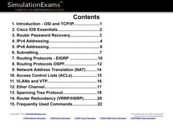
DMU Fitting SimulatorVersion 5 Release 13Page 16Recording a TrackBefore starting this scenario, you should be familiar with the basic commands common to allworkbenches. These are described in the DMU Navigator User's Guide.This task will show you how to record a track using productsThe CHAINSAW.CATProduct document is already open1. Click the Track iconfrom the DMU Simulation toolbarThe Track dialog box along with the DMU recorder and player are displayed:You can alter the name of the track by entering one in the Name field, or you can accept the defaultname provided. You can also set a speed for the movement or input a time by which the movementshould be complete.2.You are ready to record your track: select the product to moveIn our example, select DEMO CGE CHAINSAW BODY FILTERCOVER.1 either in the specificationor in the geometry.The player becomes active and the Manipulation toolbar appears
Page 17Version 5 Release 13DMU Fitting Simulator3. Select the required interpolator. In our example keep the default one (Linear)Note: you can change the interpolator type at any time during your track recording4. Move the 3D compass and click Record at each time position of your choice.If you double-click Record, the automatic insert mode is activated.Note: You can also use the Insert Key instead of clicking Record.You can modify or delete a position (referred to a shot) at any time, for this select the requiredor Step Forwardbuttons in the Playershot in the geometry (use the Step Backward shotto jump to a shot, make sure the Player unit is shot and the sampling step in the PlayerParameters dialog box is set to 1), then perform the deletion (use the Delete key or the Deleteicon) or modification. The track is automatically updated.Alternatively, you can use the Reorder Shots command,which calls up the Reorder Shotsdialog box. To move a shot up one place in the list, select the shot, and press the Up button. To move a shot down one place in the list, select the shot, and press the Down button. To insert a selected shot after next clicked shot, select the shot, click on the shot you wish it tofollow and push the After button.Note: when editing a track, you can multi-select shots to be deleted (Select CRTL key or Select SHIFT keyFor more detailed information, please read Track Editor and Recorder and Player sectionsThis is an example of what you can get:
DMU Fitting SimulatorVersion 5 Release 13Page 18The track is created and identified in the specification tree (under Tracks item and within theproduct too)4. Click OK to exit Track command. The modified position is kept
DMU Fitting SimulatorVersion 5 Release 135.Click Resetto go back to the initial position.Note: you can at any time delete the track if you are not satisfied.6. Right-click Track.1 and select track.1 item to access the track contextual menu and variousoperators.For detailed information, please read About Track Operators.For more detailed information about this menu items (referred to as track operators), seeAbout Track Capabilities and About Track Operators.7. Double-click Track.3 if you need to: replay your track simulation (use the dedicated Player) edit the track (modify a position, delete a position.)For instance play your track using the Play forward button:The time is specified in seconds in the Player (corresponds to the current time)Page 19
DMU Fitting SimulatorVersion 5 Release 13Page 208. Check the speed and duration of your track simulation and modify it if necessary.All you need to do is right-clicking Track.1 in the specification tree and selecting Properties itemfrom the contextual menu displayed.Then, enter a new speed value, the duration is recalculated.You can also modify the track name as desired.Click Ok when done.Note: the default speed is 0.001m s (see: Customizing DMU Fitting)When you modify the speed and/or duration, the default value is automatically overwritten withthe new speed value.About modifying the speed:For instance, you might need to reduce the track speed because your object is too heavy (keep inmind a track comprises of the track itself the object) , the duration is automatically recalculated(longer duration) and the speed is updated in Tools- Options- DMU Fitting- Default speed.
DMU Fitting SimulatorVersion 5 Release 13Page 21About customizing speed:If you modify the speed in the DMU Fitting tab, note that this modification will be taken into accountfor the new tracks to be created. For already created track use the Track Properties.For more detailed information, please refer to Customizing DMU Fitting
DMU Fitting SimulatorVersion 5 Release 13Page 22At any time, you can: modify the loop mode, stop at a specific step or go back to the previous step (use step backwards and step forward andstop buttons)skip to the starting position or skip to the end (to the very last recorded position)Please also see: Player
DMU Fitting SimulatorVersion 5 Release 13Page 23Using Automatic Path FinderBefore starting this scenario, you should be familiar with the path finder command, pleaserefer to Path finder chapter.This task will show you how to use the path finder capability on a track simulation.The CHAINSAW.CATProduct document is already open1. Select the track created in the previous task (Track.1) either in the geometry area or inthe specification tree.Note: you can also click the Path finder icon first and the object afterwards, in this case,the select dialog box lets you choose the objects2.from the DMU Check Toolbar.Click the Path finder iconThe Path Finder dialog box is displayed. and lets you select options for: (The Basic mode is set by default)
DMU Fitting SimulatorVersion 5 Release 13Page 24Visualization On (shows the object move and its various positions during calculation. You can stopthe process at any time) Off (You are not allowed to stop the process and you do not see the progression Strombo (shows positions based on a specific parameter (every 20 steps)Steps3. Small Medium LargeKeep the default settings:Visualization: onSteps: Medium4. Check the Ignore collisions checkbox to get rid of the irrelevant interferences.5.Click Apply to confirm your operation.The progress bar is displayed letting you monitor and, if necessary, interrupt (Stop option) thecalculation.
DMU Fitting Simulator5.Version 5 Release 13Click Ok.This is what you obtain:The path finder is a track operator.It is identified in the specification tree under a new track (Track.2), Track.1 isThe option "ignore collisions" is identified under Parameters (knowledge parameters)Please see: Managing Operators' Options As Knowledge ParametersPage 25
DMU Fitting SimulatorVersion 5 Release 13Page 26By default, the OK button does not perform the smooth, please select Tools- Options Digital Mockup- DMU fitting. Check the Automatic Smooth option.You are now ready to get rid of the unnecessary positions detected during path finderoperation.
Version 5 Release 13DMU Fitting SimulatorUsing The Smooth CommandThis task will show you how to smooth the automatic path finder defined in theprevious task.1.Click the Smooth iconfrom the DMU Check toolbar2.Select the required track in the Select dialog boxdisplayed.i.e: Track.4The Smooth dialog box appears3.Click OkThis is what you obtain:Page 27
DMU Fitting SimulatorVersion 5 Release 13Page 28The smooth result ( track operator) is identified in the specification tree under Track.2The parameters changed are identified too.Note: you can edit the parameters double-clicking them to display the Edit parameterdialog box.For example, if you double-click Translation step in the specification tree:Note: You can also display the track properties using the contextual menu.
DMU Fitting SimulatorVersion 5 Release 13Page 29Updating a TrackThis task will show you how to update a track. We applied consecutively the followingtrack operators: path finder and smooth, we need now to update the resulting track.1.2.Right-click the track to be updated in the specification tree, i.e Track.4Select the Track.4 object- Update track items from the contextual menu displayedThe path finder and the smooth computations are automatically launchedThe track is updated accordingly
DMU Fitting SimulatorVersion 5 Release 13Page 30
Version 5 Release 13DMU Fitting SimulatorPage 31Replaying a TrackThis task will show you how to replay a track using the dedicated Player1. Double-click the track created (i.e. Track.1) in the specification tree or click the Track iconin the DMU Simulation toolbar2.The player is displayed:3.Click the Parameters icon4. The Play Parameters dialog box appears:5.Modify the time step and the temporization values if necessary.6.Use the VCR buttons or the slider to simulate your track. skip to beginningstep backwards play backwards stop play forwards step forwards
Version 5 Release 13DMU Fitting Simulator skip to endFor more information, please refer to PlayerPage 32
Page 33Version 5 Release 13DMU Fitting SimulatorDefining a Swept VolumeBefore starting this scenario, you should be familiar with the basic commands common toall workbenches. These are described in the DMU Navigator User's Guide.This first task will show you how to enter the Fitting Simulator workbench and select yourproducts.1.Select Track.1 in the specification tree and click the Swept volume iconThe Swept volume dialog box appears:2.Click Preview.The computation is in progressThe preview window appears:.
DMU Fitting SimulatorVersion 5 Release 133. Click Save in the Swept volume dialog box.The Save As dialog box is displayed4.Select cgr file from the drop-down listPage 34
DMU Fitting SimulatorVersion 5 Release 13Page 355. Enter a meaningful name and click Save.6.Insert the SWEPTVOLUME track.cgr into Product1, for this right-click Product1 and selectComponents- Existing Component from the contextual menu displayed.The Swept volume is identified in the specification tree and in the geometry area.
DMU Fitting SimulatorVersion 5 Release 13Page 36
DMU Fitting SimulatorVersion 5 Release 13Page 37Using ShuttlesBefore getting into the detailed instructions for using DMU Fitting Simulator, the followingtutorial aims at giving you a feel of what you can do with the product. It provides a step-bystep scenario showing you how to use key functions.The main tasks described in this section are:Starting a SessionExploding a ProductDefining a ShuttleRecording a SimulationReplaying the SimulationThese tasks should take about 15 minutes to complete.
DMU Fitting SimulatorVersion 5 Release 13Page 38Starting a Fitting Simulator SessionBefore starting this scenario, you should be familiar with the basic commands common toall workbenches. These are described in the DMU Navigator User's Guide.This first task will show you how to enter the Fitting Simulator workbench and select yourproducts.1.Select Digital Mockup - DMU Fitting from the Start menu.The Fitting Simulator workbench is displayed.2.Select File- Open.The File Selection dialog box displays:3. Select the CHAINSAW.CATProduct from the samples folder.4. Click Open to open the selected files.The specification tree is displayed showing all the selected products. In our example, theCHAINSAW.CATProduct has been divided in four main groups of objects.Note that you can also select model files using insert- existing component.In this case, select the desired model files by clicking the first one then shift-clicking thelast one you want.
DMU Fitting SimulatorUse the Fit All In iconVersion 5 Release 13Page 39to position the model geometry on the screen.Clicking off View - Specifications visible in the menu bar removes the specification treeand lets you use the entire screen for the product. You can also use the F3 key to togglemore quickly.
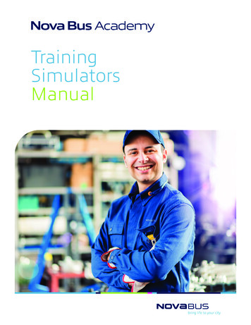
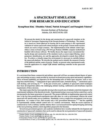
Version 5 Release 13DMU Fitting SimulatorPage 40Exploding a ProductThis task illustrates the use of the Explode capability. Exploding the view of anassembly means separating the components of this assembly to see their relationships.At any time though, you can check the product structure via the specification tree. Theexplode capability allows you to fully understand the product structure in a 3D context.CHAINSAW.CATProduct document is opened1.Select Product1 in the specification tree.2.Click the Explode icon.The Explode dialog box and the Manipulation toolbar are displayedProduct 1 is the assembly to be exploded. The Depth parameter lets you choosebetween a total (All levels) or partial (First level) exploded view.3.Set All levels if not already set.4.Set 3D as explode type.You can now generate a sequence from the exploded view, all you need to do is clickthe Generate Sequence checkbox before launching the explode operation.For more detailed information refer to Generating a Sequence from an Exploded View
DMU Fitting Simulator5.Version 5 Release 13Page 41Click Apply to perform the operation.The Scroll Explode field gradually displays the progression of the operation. Theapplication assigns directions and distances. Once complete, the assembly looks likethis:The interest of this operation lies in the ability of viewing all components separately.You can easily move products within the exploded view using the 3D compass.
DMU Fitting Simulator6.Version 5 Release 13Click Apply to confirm the operation or click Cancel to restore the initial view.Page 42
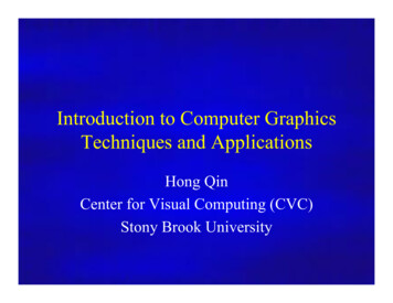
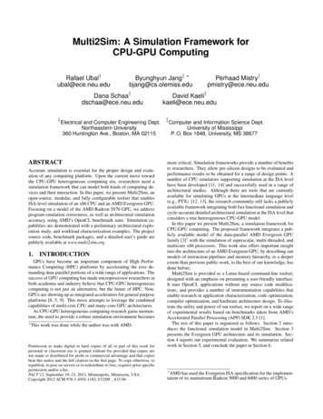
DMU Fitting SimulatorVersion 5 Release 13Page 43Defining the ShuttleBefore starting this scenario, you should have loaded your CHAINSAW.CATProduct as describedin the previous step.A shuttle is a set of products defined explicitly by selecting products individually.Shuttles are persistent and can be stored in the document.This task explains to you how to define the list of products you want to move together.1. Select a product in the geometry area or in the specification tree.2. Ctrl-click other products to add them to the initial selection3.to create a shuttle:Select Insert- Shuttle. from the menu bar or click the ShuttleThe Edit Shuttle dialog box and the Preview window appear.The 3D compass automatically positions according to the to-be-created shuttle axis. See below:
DMU Fitting SimulatorVersion 5 Release 13Page 44You can define a maximum angle of rotation for the shuttle around the absolute axis you select.It means the shuttle motion is defined and validated with respect to the angle value defined.The Preview window shows selected products.4. (Optional)Enter a meaningful name for the shuttle you want to create.
DMU Fitting SimulatorVersion 5 Release 13Page 455. Click OK to create the shuttle.The shuttle is identified in the specification tree.Shuttles created in this manner are persistent and can be stored in the document. They arelisted as separate entity in the specification tree and can be selected at any time and modified.
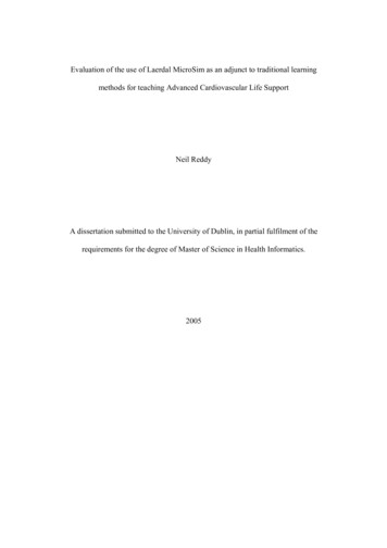
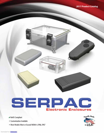
DMU Fitting SimulatorVersion 5 Release 13Page 46Recording a SimulationBefore starting this scenario, you should have created a "Shuttle" as described in the previoussteps.This task explains how to quickly define the motion of a "Shuttle" and to record it in asimulation object.1. Select Shuttle.1 in the specification tree.2.Select Insert- SimulationThe 3D compass automatically positions according to the shuttle axis.The Edit Simulation dialog box and the Preview window appear.You are ready to record a simulation.
DMU Fitting SimulatorVersion 5 Release 13Page 47You can now record a simulation with an animated viewpoint. For this, activate the Animateviewpoint option. For more details, please refer to Animating a Viewpoint .The first shot: shuttle in the origin position is already recorded in the simulation.3. Select the manipulator to move the shuttle as desired.4. Drag the cursor to the desired shuttle location.
DMU Fitting SimulatorVersion 5 Release 13Page 485. Click Insert to save and insert in the "Simulation" the shuttle in the new position.6. Insert another location in the same manner:You can select and drag all the components of the manipulator (axis, plane, arc, point) tomove in different ways.7. You can do several manipulations before inserting a new position in the "Simulation".8. Click OK to end the Simulation creation.The simulation is identified in the specification tree.
DMU Fitting SimulatorVersion 5 Release 13Page 49
DMU Fitting SimulatorVersion 5 Release 13Page 50Simulating a ReplayBefore starting this scenario, you should have created a "Simulation" with a shuttle atdifferent locations as shown in the previous step. The CHAINSAW.CATProduct document isalready opened.This task explains how to run a shuttle motion recorded in a "Simulation" using theSimulation command.1. Double-click your "Simulation" in the specification tree (Simulation.1)The Edit Simulation dialog box and the Preview window appear.
DMU Fitting SimulatorVersion 5 Release 13Page 51If you checked the Animate viewpoint option in the simulation recording, you can nowanimate viewpoints while recording a simulation. They are taken into account. For moredetails, please refer to Animating a Viewpoint.You also can select a "Simulation" graphically by clicking on the tracks.2. Modify the interpolation value as desired. For example: 0.043. Click the Play Forward button.The recorded motion is replayed.
DMU Fitting SimulatorVersion 5 Release 13At any time, you can go back to the starting shot. Use the VCR buttons as desired: Play Forward (step by step) Go
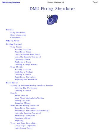
DMU Fitting Simulator is a software dedicated to simulating part motions for assembly and maintainability issues. It addresses the Design Review Environment of Digital Mock-Ups (DMU) and can handle a wide range of products from consumer goods to very large automotive or aerospa