Transcription
AAS 01-367A SPACECRAFT SIMULATORFOR RESEARCH AND EDUCATIONByungMoon Kim , Efstathios Velenis†, Patrick Kriengsiri‡, and Panagiotis Tsiotras§Georgia Institute of TechnologyAtlanta, GA 30332-0150, USAWe present the details for the design and construction of a spacecraft simulator at theSchool of Aerospace Engineering of the Georgia Institute of Technology. The simulator is based on a hemi-spherical air bearing and its main purpose is the experimentalvalidation of various spacecraft control strategies on the ground. Custom-made reactionwheels are used as torque actuators. The implementation of the attitude control algorithms is done on-board using a PC104 type Pentium 266MHz computer motherboardbundled with in-house software. We briefly discuss the major issues encountered during the design and construction of the simulator (such as sensor output filtering, motorparameters identification, etc) and the approaches developed to remedy these difficulties. To achieve a virtually torque-free environment it is necessary to carefully balancethe spacecraft platform. We describe the method used to identify the moment of inertiaof the platform and the center of gravity. Finally, we present some experimental resultsfrom the application of a simple LQR attitude stabilizing controller on the spacecraftsimulator.INTRODUCTIONIt is envisioned that future commercial and military spacecraft will have an unprecedented degree of autonomy and pointing accuracy, made possible by increased on-board processing speed and memory capabilities.These on-board capabilities are imperative for the demanding tasks of future space missions, such as verylarge base interferometry, 1–3 deployment of space optical telescopes, formation flying, 4–7 autonomous spacecraft docking, and servicing etc. 8–11 In the past several years, a plethora of spacecraft control techniqueshave been developed that address the challenging attitude tracking, stabilization and disturbance rejectionrequirements of these missions.One major aspect that has been typically missing in the research area of attitude control development is theexperimental validation of the theoretical results. Experimental testing is necessary before control laws can beincorporated in the future generation of spacecraft. The greatest difficulty in implementing spacecraft controllaws is the fact that ground-based experiments must take place in a one-g environment, whereas the actualspacecraft will operate under zero-g conditions. Simulating a zero-g, torque-free environment is not an easyproposition. As a matter of fact, until recently only a few government laboratories 12, 13 had the capabilityto experimentally validate attitude control laws in a realistic environment. With the recent explosion ofcommercial (as well as military) satellite industry there is an increased need for rapid prototyping and testingof the most promising attitude control algorithms proposed in the literature.Several non-government agencies and academic institutions have recently initiated the development andconstruction of spacecraft simulators that can be used to educate the next generation of spacecraft dynamics GraduateStudent, E-mail: gte342k@prism.gatech.edu, Tel: (404) 894-9108, Fax: (404) 894-2760.Student, E-mail: gte600q@prism.gatech.edu.‡ Undergraduate Student, E-mail: gte762i@prism.gatech.edu§ Associate Professor, E-mail: p.tsiotras@ae.gatech.edu, Tel: (404) 894-9526, Fax: (404) 894-2760. Corresponding author.† Graduate1
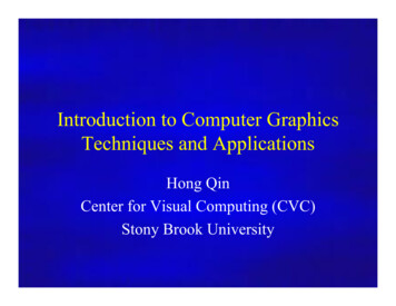
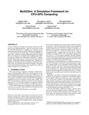
and control engineers. This article describes the recent efforts at the Georgia Institute of Technology to design,build and test such a (relatively low-cost) spacecraft simulator facility. The purpose of the GIT simulator isto evaluate and improve various theoretical controllers available in the literature, and to develop new controlstrategies in an experimental framework. This simulator is also used to demonstrate the fundamentals ofspacecraft attitude dynamics, attitude estimation and control to the graduate and undergraduate students atGeorgia Tech.Accurate balancing of the platform is necessary to accurately duplicate a torque-free environment. Perfectbalancing is obtained when the center of gravity coincides with the center of rotation of the platform. Toachieve this goal, an identification algorithm was developed to estimate the moment of inertia matrix and thecenter of gravity of the whole platform. This algorithm can also be used to estimate the inertia matrix forlater use in attitude tracking and indirect adaptive control schemes. The major components of the spacecraftsimulator are described in detail in the sequel. Results from the testing of a linear stabilizing controllers arealso reported.OVERVIEW OF THE SPACECRAFT PLATFORMThe spacecraft “bus” at GIT consists of a 24in diameter (0.75in thick) aluminum disk that is supported ona hemi-spherical air bearing. The platform supports all the various spacecraft components, i.e., sensors,actuators, control computer, etc. See Fig. 1.AmplifiersBattery x2Battery x2Battery x2Wireless ModemDynamicMeasurement UnitCounterweightAir bearingWheelMotorFigure 1: Schematic of spacecraft platform and componentsThe air-bearing is operated using compressed air from an external source through an air filter. The airfilter removes moisture, oil and other impurities and regulates the air pressure (roughly around 25-40 psidepending on the normal load). Under the aluminum disk are mounted three wheels which can be operatedat momentum or reaction wheel (RW) mode. The wheels are each paired with a DC motor and amplifier.Encoders installed on the DC motors provide angular feedback. Power for the entire system is provided bysix 12V batteries connected pairwise in series to provide 24V at a time. On top of the aluminum disk, a2
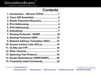
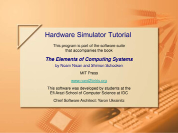
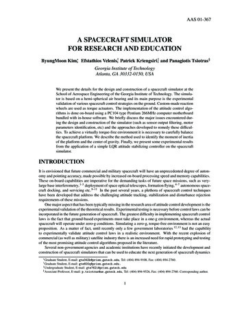
Figure 2: The Spacecraft Simulator.PC104 type Pentium 266MHz main computer board (CMP5e) is used for the data acquisition, recording,controller implementation and communication. The remote PC and the CMP5e are connected via a wirelessRS-232 serial port. The remote PC monitors the status of the experiments and issues control commands suchas start/stop, while the CMP5e unit controls the motors directly.In order to properly simulate the motion of a spacecraft in a gravity-free environment it is essential tobalance the spacecraft platform so that the center of rotation coincides with its center of mass. Severalcounterweights are used to balance the whole assembly.A photograph of the completed spacecraft simulator is shown in Fig. 2. An outline of the interconnectionof the several simulator subsystems is shown in Fig. 3.SUBSYSTEM DESCRIPTIONAir Bearing, Platform and BatteriesThe air bearing that supports the platform is located on top of a pedestal structure (3 ft high) and it allows theplatform to move without friction 30 deg about the two horizontal axes (x and y) and 360 deg about the vertical(z) axis. The bearing is the SRA 300 spherical air bearing designed and manufactured by Specialty Components Inc. The bearing itself is made of 6 00 aluminum and can hold up to 748 lbf of load when operating at80 psi air pressure. The GIT platform bearing is operated at 30 psi which corresponds to approximately 300lbf of vertical load.The aluminum platform provides a mounting surface for the several simulator subsystems. The locationof the center of mass (desired to be at the center of rotation of the simulator – in this case the center of thebearing rotor) can be changed by positioning different counterweights in various slots and holes located atseveral places on the platform. The platform was designed and manufactured in the Georgia Tech Aerospacemachine shop. Care has been taken to position all major components of the simulator, such as momentumwheels, batteries, amplifiers, etc. in a symmetric fashion. This makes it easy to balance the platform as wellas locate the principal axes.Power to the simulator is provided by three pairs of rechargable Sealed Lead Acid batteries rated at 12 V3
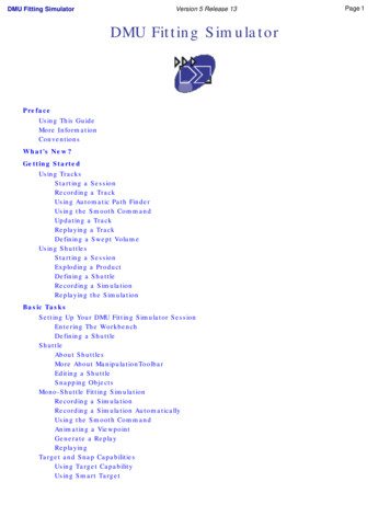
REMOTE PCPLATFORMDifferential Analog Input ( 10V)RS/232CMP5e Pentium BoardDMM32Data Acquisition BoardCOM1,2ADDIODAInterface BoardDC/DC rAMPMotorEncoderIndex & channel A pulses24V24Vp,q,r, φ,θ,ϕ,ax,ay, az24VDMU24VBATTERYFigure 3: Overview of the spacecraft simulator component interconnection.and 5 Ah. Each pair of batteries is connected in series to provide a 24 V. The batteries are then in turnconnected to a DC converter which distributes the power to each spacecraft simulator component.Spacecraft Attitude SensorThe main purpose of the spacecraft simulator is to test several feedback attitude control laws. In order toimplement the various controllers, measurements for the Eulerian angles and the angular rates is required.A dynamic measurement unit (DMU-AHRS) by Crossbow, Inc. was chosen as the attitude sensor unit. TheDMU-AHRS provides Euler angles, angular rates, and linear acceleration. It can measure roll and pitchangles of 90 Æ and heading angle of 180 Æ. The RMS noise level in Euler angle measurement signal is0.1Æ . The angular rate range is 150 Æ /sec and the RMS noise level is 0.05 Æ/sec. The accelerometer rangeis 2g and the RMS noise is 0.002g. Note that the peak to peak noise is about six times larger than theRMS noise level. All the measured values are available in both RS-232 and analog signal output. The analogsignal provides faster sampling rates, while the RS-232 port provides digital data directly without introducingadditional noise. The signals from the digital output were chosen after taking into account the requirementsfor noise-free operation.Momentum Wheel Speed and Acceleration SensorThree encoders, rated at 500 counts/turn, are used to measure the angles of the momentum wheels. Bydifferentiating these angles, the rotational velocities and accelerations of the wheels are calculated. A digitalfilter was designed to estimate angular velocities and accelerations from these angular position measurements.Alternatively, a tachometer can be used to measure angular velocity directly. Differentiation and filtering arestill required to estimate angular acceleration in this case. We have used encoders instead of tachometerssince the noise in the analog tachometer output can be avoided, and small velocities can be measured moreaccurately. One disadvantage of the encoders is that the time delay caused by filtering is typically larger than4
that for the tachometer. This delay, however, can be kept small by careful filter design.A flip/flop circuit was designed to get angular velocity and acceleration from the encoder signals. Specifically, each encoder has two slots, A and B, on its disk. These two slots provide two signals that have differentphases, which give directional information. If A is in leading phase, the motor is spinning clockwise andvice versa. As is shown in Fig. 4, a flip-flop gate holds the status of A at the rising edge of B. When A isin leading phase, the flip-flop output, Q, is 1 and the counter 0 will have 500 pulses inputs per turn and viceversa. Thus, counters 0 and 1 measure clockwise and counter-clockwise rotation, respectively. The angle ofthe wheel is the difference between them. Figure 5 shows the complete schematic of the encoder signal proRIGHT TURNLEFT TURNADQCLKQACOUNTER 0BBQQQQCHN ACNT0CNT0CNT1CNT1COUNTER 1CHN BFigure 4: Encoder signal decodingcessing circuits. Note that two 8253 timer/counters are used. Two 8253 have three counters each. Since threeencoders need 6 counter, all counters in two 8253 were used. The control signals for the 8253 – i.e., address(A0,A1,A2), read (RD), write (WR), chip select (CS) and data signals (D0-D7) – are connected to the digitalinterface of DMM32. Thus, the control signals A0,A1,A2, RD, WR and CS are need to be implemented /WRA2174LS74VCCHEADER 511141612CLGNDINDEXCHN AVCCCHN 3B4CHN A825365CHN 113CHN B1114169151874LS74CHN A192074LS00VCCHEADER 5A0A1U3CQ10CLGNDINDEXCHN AVCCCHN 54321825374LS00VCCHEADER 344U6AU4APR3GNDINDEXCHN AVCCCHN BQQ53102CLK8A29674LS0074LS0074LS74VCCHEADER 122232425262728293031323334U4B4CHN A65CHN B74LS00Figure 5: Encoder signal processing: phase detection and wheel turn countMotors and Power AmplifiersThree Maxon DC motors (Model 143683) with a 24V nominal voltage are used as actuators in lieu of expensive, space certified reaction/momentum wheels. The stall torque of each DC motor is 783mNm, themaximum continuous torque is 88.8mNm, and the maximum permissible speed is 8200rpm. Each motor is5
driven by a Power Amplifier made by Copley Control (Model 403). It can deliver a continuous power of120W (24V input) and peak power of 240W (24V input). The amplifier generates a PWM output for precisetorque control. During initial testing, it was observed that this power amplifier produces reverse current incounter-clockwise spin, which can cause damage to the power supply circuit or other electronic components.Therefore, a diode (D1 in Fig. 6) was used to prevent the reverse current and a capacitor (C1 in Fig. 6) wasused to flatten the power fluctuation. The power distribution schematic is shown in Fig. 6 24VDMU 15VVOLTAGEREGULATORS 12V 5VWIRELESSMODEM,FDD,. 5V24V DCD1C14700 MFDC/DCCONVERTER IFIERMOTOR3ENCODER3Figure 6: Power distribution diagramThe CPU and I/O BoardsThe electronics suite includes the CPU unit, the I/O board, interface board and RF Modem; see Fig. 7. TheCPU board runs the software that needs to handle all hardware controls, timers, packet-based communications, and filters for sensor signals. Although many of these tasks can even be done with a 8-bit CPU if theprogram is written carefully, fast 32bit processors are available in today’s market at a reasonably low cost. Wechose a PC104-type Intel mobile Pentium 266MHz board since various powerful software development toolsand techniques for PC can be used without modification. The board model is CMP5e, from Ampro Computers. This CPU board has 32MB main memory, an 8MB memory disk and 2 Serial ports. The dimensions ofthe board are 3.6” x 3.8” x 0.9”.Three digital-to-analog converters are required for the motor amplifiers since they need analog inputs forthe torque commands. The DMU needs 9 analog-to-digital converters for Euler angles, angular velocity andacceleration if analog outputs are used instead of digital outputs. Even if only digital outputs are chosen, A/Dcapability is still desired for future extension of the capabilities of the simulator. A digital interface is alsorequired to read counter information. To meet all of these requirements, a PC104 type analog interface board,DMM32 (from Diamond Systems Corp.), is installed on top of the CMP5e. This board has 32 single-endedor 16 differential 16-bit A/D converters that have sampling rates of 200kHz, four 12-bit D/A converters and24 programmable digital I/O. The CPU and I/O boards are shown in Fig. 8.6
Figure 7: Top view of spacecraft platformInterface BoardThis board provides terminals for power, communications, as well as sensor signals for easy interface. Voltageregulators and a DC/DC converter for 5V, 12V and 15V voltage sources for various components are placed inthis interface board. This board also has flip-flops and counters to measure the encoder signal. These countersare interfaced to the DMM32 via the digital I/O ports of the DMM32. The interface board was designed andbuilt in-house.SoftwareTwo software applications were developed separately for both the CMP5e on-board computer and the remotePC computer. The latter is used to send initiate/stop commands, for health monitoring, post-experiment dataanalysis and plotting etc. The CMP5e and the remote host communicate via a wireless RF serial modem at aspeed of 56K baud. The executable module for the CMP5e (space.exe) implements hardware initialization,controller initialization and starts a 0.1 millisecond precision timer to schedule various tasks and communications. This program is developed and compiled on the remote PC and then it is downloaded to the CMP5e viaa serial communication interface. In cases space.exe has errors that cause the system to crash, the CMP5eneeds to be restarted. When the CMP5e is restarted, a small starter program is then executed first and theonboard computer waits for a new executable of space.exe or a quit command. In the latter case, it executesthe existing version of space.exe.The remote PC runs a separate program (ComCen.exe). This is a multiple view-based GUI that implements the control toolbar, monitor view, message view and others. All multiple views are updated whenevera new data packet is delivered by a virtual callback function. The programs on the RemotePC and the onboard computer communicate with each other through an RS-232 serial connection with four types of customdeveloped packets: data, message, file and command packets. During the experiment, the time history of allstate variables are recorded in a binary format history file. This file is transferred after the experiment to theremote PC and is converted to a matlab *.m file for further analysis.7
Figure 8: Close-up view of electronicsFILTERING AND IDENTIFICATION OF MOTOR PARAMETERSFilter DesignSince the encoder signal provides angular information, we need to differentiate it once to get angular rate,and then once more to obtain angular acceleration, if necessary. Since differentiation of sensor signals alwaysmagnifies noise, filtering of the signal is necessary. For the spacecraft simulator, either a Butterworth orChebyshev type 1 filter can be used, depending on the high frequency attenuation and time delay limitations.The frequency response of the filter used for angular rate and acceleration information is shown in Fig. 10.Estimation of Motor Damping and Choice of Reaction WheelsIn order to keep the output torque sufficiently larger than the friction and magnetic damping torques, it isimportant to know the friction and magnetic damping effects of the motor. This allows proper sizing of themomentum wheels. In order to estimate the damping torque of the motor, the wheel was spun up to some highspeed and then the motor/wheel was left to decelerate slowly due to those damping effects. Since the inertiaof the wheel is accurately known, one can estimate the magnitude of the damping torque. Figure 11 showsthe result of this experiment when the motor axis is horizontal. As is shown in this figure, the damping torqueis increasing as the velocity increases and has a nonlinearity near zero velocity. Note that in the high-speedregion, damping is not negligible and thus high-speed operation should be avoided. These damping torquescan be an important factor that affects the sizing of the wheels. Larger wheels provide a larger torque andsmaller damping. Smaller wheels provide good resolution in torque output but they also have more dampingsince they usually operate at higher speeds.Identification of Motor DynamicsThe static motor gain can be calculated from the specifications of the motor, D/A converter setting and motoramplifier gain. However, by identifying the transfer function between torque command and response, we cancalculate the dynamic behavior of the response as well as the gain of the motor. A least-squares fit was usedfor the transfer function identification. Figure 12 shows the transfer function between the voltage input to8
Figure 9: Remote PC side software panelthe amplifier and the torque output. The gain of the motor is about 0.4 Nm/Volt at zero frequency and it isdecreasing at high frequency. As is shown in this figure, the motor response is quite fast and the gain doesnot change much up to approximately 10Hz. Since this frequency is much higher than the typical spacecrafttorque response frequency, it was decided that additional efforts to improve motor response was not required.IDENTIFICATION OF MOMENT OF INERTIA MATRIXOne way for calculating the moments of inertia is by using a CAD model. An AutoCAD model for the wholeassembly was thus developed and mass densities for the various components were assigned for the wholesystem (see Fig. 1). This model was detailed enough to include small components such as bolts and nuts. Themass distribution of the sensor and electrical components were assumed to be homogeneous and the electricalN 4, cutoff 0.1N 4, cutoff 0.1Delay (sec)Magnitude 0.04 510buttercheby1 1010 0.06 0.08buttercheby1 0.1 0.1200.20.40.60.8ω/π (1 half sampling freq.)0Figure 10: Filter design90.20.40.60.8Normalized Frequency, ω/π
0.018Friction and Motor Damping Torque (Nm)0.0160.0140.0120.010.0080.0060.0040.0020 600 400 2000ω (rad/sec)200400600Figure 11: Friction torque versus speed during decelerationwires and some other small electrical parts were neglected. This method gives a fairly accurate estimate ofthe inertia matrix with minimal effort. One drawback of the MOI estimation matrix using a technical drawingpackage such as AutoCAD is the difficulty associated with designing a complex 3D CAD model. On the otherhand, experimental methods are not affected by the complexity of the structure. Traditional bifilar or trifilarpendulum methods can determine the inertia values from the period of the pendulum. Other experimentalmethods, such as the ones described in Refs. 14 and 15, measure the external reaction forces by load cellsand find the inertia matrix that best fits the equation of motion in a least-squares sense. The major drawbackof such methods is the significant amount of effort required for setting up and conducting the experiments.Ideally, a spacecraft simulator operates in a torque-free (or almost torque-free) environment and there isno need to measure the reaction forces. Moreover, a spacecraft simulator has fully-featured motion sensors,which makes the experimental inertia estimation much simpler. In Ref. 16, the authors proposed the useof a coasting maneuver. A solution was found after converting the full nonlinear equation of motion to astandard least-squares form. An optimal coasting maneuver was also proposed based on stochastic analysison the sensor noise. Another approach is realtime inertia estimation strategies for the case when the inertiaof spacecraft is changing. Bergmann et al 17 proposed a mass property estimation strategy using nonlinearfiltering, together with a simplified (nonlinear) model for the equation of motion. An input selection methodto generate a feasible inertia estimation maneuver for this estimator was also proposed in Ref. 18. Otherapproaches for inertia estimation are those often found in spacecraft adaptive control literature. 19, 20Below we describe the moment of inertia and center of gravity estimation scheme used for the GITs/c simulator. The method is based on a standard least-squares identification algorithm using a series ofexperiments. In each experiment, a torque profile is commanded and the angular accelerations of the platformare recorded. Off-line analysis of the input-output data gives a very accurate estimation of both the momentof inertia matrix and the center of gravity of the platform. For the comparison purposes, the numericalapproximation from AutoCAD model is also provided.Representations of Attitude and KinematicsA schematic of the spacecraft platform is shown in Fig. 13. Let an inertial frame I and a body frame S with and the basis of S istheir origins at the bearing center B , as in Fig. 13. The basis of I is denoted by I ; J ; K denoted by i; j ; k. The unit vectors along the three wheel axes be denoted by i1;2;3 . The unit vectors i1;2;3 aregiven in the body frame asp(1)i1 i ;i2 1 3 i j;2210i3 k
Motor Transfer Function : Torque/VoltInput Voltage0.50.10.050.3VoltGain [NOT in dB]0.400.2 0.050.10 1100110 0.1210100246Time [sec]8100.06 500.04 1000.02Torque [Nm]PhaseTorque Response0 150 200 250realsim.0 0.02 0.04 300 1100101 0.06210ω [rad/sec]100246Time [sec]810Figure 12: Identified motor dynamics and response comparisonTo describe the attitude of spacecraft, a 3-2-1 Euler angle sequence. The relevant direction cosine matrix(DCM) that is used to represent the transformation from the inertial frame to the spacecraft body frame isgiven by2(2)[T ]IS i I4 j I k I 32 i J i Kcθ cψ54 ssccφ sψj J j K φ θ ψ csc sφ sψk J k Kφ θ ψ cθ sψsφ sθ sψ cφ cψcφ sθ sψ sφ cψ3sθsφ cθ 5cφ cθThe kinematic equations are given by89 φ̇ (3)21 sin φ tan θcos φθ̇ 4 0:;0 sin φ cos θψ̇389cos φ tan θ p qsinφ 5:;cosφ cos θrEquation of MotionThe full nonlinear equations of motion can be derived starting from the momentum of a differential masselement δm as illustrated in Fig. 14. Note that the center of mass is located at S . The velocity of δm is givenby v I ωS r where r is the position vector from B . The velocity of a differential mass δm of the wheel isgiven by(4)v wi IωS rwi S ωwi ρ 11
i3x iB jJ yZ i2 KY i1 I kzZFigure 13: Definition of coordinatesI ωSB rδm rSS rwi rw iwi ρ vwiS ωwiFigure 14: Definition of mass center and momentum of δmThe angular momentum of whole system is calculated asZ H SZ (5) I I3r I ωS r δm r I ωS (S w) B (S w) B r wi i 1 wi3 Z r δm rwii 1 wi S wZ rw i ω II S i 1wi w iωS wi ωS rwi S ωwi ρ δm 3ωI SIZωS wiwi ρ δm ρ3 δm Zi 1 wiρ ωS wi ρ δmωS wiwi w where I i is the inertia dyadic of i th wheel with respect to the wheel’s mass center w i . Iis the inertiadyadic for the eitire body of spacecraft and wheel with respect to bearing center B . For convenience, let(S w) B wi w I Iand Ii I i . Since viscosity effects of the air bearing are neglected and pressure is alwaysnormal to the spherical bearing surface, the only external torque exerted on the bearing center is the one by(S w) B 12
gravity. Euler’s theorem gives the equations of motion of the platform as T rS mgk (mg r ) k S 3d I S I SI ω ω I I ωS dti 1S (6) II wd i S wi I wiI ω ω Ii S ωwidti S I ωS I I ωS ω Ii S ω wi I ωS S ωwi Ii S ωwi3 i 1Let a unit vector along the symmetry axis of the wheel w i be ii and choose the other two bases vectors ji andki so that they are orthonormal and form right handed coordinate system. Since the wheels are axisymmetric,wi wi wi Ii I11ii ii I22ji ji I33ki ki . Also, since the wheels always rotate along ii , S ωwi ωi ii . As a result, ωS wi(7) Ii S ωw i I11w ii ii I22w ji ji I33w ki ki ωi ii w ωi ii I11 ωi ii 0 ωi iii i i i Finally, we have3(mg rS )(8) k I I ω S I ωS I I ωS i 1 wi I ωS Ii S ωwiIi S ω Estimation of the Inertia MatrixSince our experimental platform uses three momentum wheels, we can achieve arbitrary motion by sendingacceleration commands to the wheels. Assuming that aerodynamic and motor bearing friction forces aresmall, the only external torque is the torque caused by gravity, which can be identified along with the inertiamatrix. The estimation scheme uses the fact that the equations of motion are linear with respect to the inertiacomponents and gravity. Thus, the estimation problem can be solved easily by a least-squares algorithmimplemented in regression form. 16fxg fyg[A](9)During identification, wheel acceleration commands are applied in all three directions i; j and k definedin Fig. 13. Since the platform cannot exceed pitch and roll ranges in excess of 30 deg, a stabilizing LQRcontroller is turned on to reorient the platform to the initial position if the angular pitch and roll motionsexceed these values.To derive the regression expression (9) from equation (8), we need to re-write the latter in matrix form.To this end, let Twi S be the transformation matrix from frame of i th wheel ( ii ; ji ; ki ) to S ( i; j ; k). From Figure15, Twi S are given as2Tw1 S(10)1 4 00230 01 0 50 1;Tw2 S 4p123 20 p233 2 01 20 501;Tw3 S30 0 1 4 0 1 0 51 0 0Let f ωgS and [I]S be ω and I written in frame S, respectively. Let [ ω̃]S denote the cross product in matrixwi form.21 Using the fact that I i S ωwi I11ωi ii and by defining f I ωS gS [ p q r]T one finally obtainsTS mgf rS K gSfmg r gwhere fK g is K expressed in the spacecraft body frame. Note that f K g is a function of φ θ and ψ as follows89 89 892(q1 q3 q2q4 )sin θ i K 2(q2 q3 q1q4 )sin φ cos θ(12)fK g : j K ; : :;22 q 2 q 2 ]T ;cosφ cos θqqk K1234 (11) S [K̃ ]S S 13SSS;
i1 j1 i i j j3 j2 j i2 j i3 kFigure 15: Coordinate TransformationsNow, equation (8) can be written as0 [K̃ ]S fmg rS gS [I]S38 w9 I11i ω̇i i 1000(13) n @Twi S :fxg fT gI Sωof gI SI S [ ω̃ ]S [I]S ωS8 w91 I11i ωi I SA0 ω S Twi S;:;Sf g0 [A]where [A]; fxg and fT g are2[A ] 4(14)fxg fT g ṗprpqI118 :q̇ prd qrp 2 q2I12I13ṙ pqr 2 p2ṗ qrI22I239q 2 r2ṙ pqq̇ prqrq̇pqI33mg rS x2w11 w2I112 I11 ω̇2 pω̇1 3 w22 wI11 ω̇2;I113 ω̇304 rq3qrprṙmg rS y[ K̃ ]S 5mg rS z38q p 5:0r0p T9w11 w2I112 I11 ω2 pω1 3 w22 wI11 ω2;I113 ω3Let [Ai ] and fTi g be values of [A] and fT g at i th time step. Define [Ã] and fT̃ g as2(15)[A 1 ]36 [A 2 ] 775:::[Ã] 64;8 fT1gfT2g ::::fT̃ g 9 fTng ;Finally, the least square estimation of fI g that minimizes jj[ Ã]fI g fT̃wgjj is given by(16)fI g [Ã]† fT̃ g[A n ]where [Ã]† is generalized inverse of [ Ã].To verify the regression equation and examine the numerical error from the matrix inversion, the previousinertia estimation scheme was tested using simulation data. A simple angular velocity stabilizer is used for
We present the details for the design and construction of a spacecraft simulator at the . batteries, amplifiers, etc. in a symmetric fashion. This makes it easy to balance the platform as well as locate the principal axes. Power to the simulator is provided by three pairs o