Transcription
P/N 830-0061-0OSR 11-S-2492OPERATOR MANUALATILLA-200TMAcquired Tactical IlluminatorLaser AimerNivisys, LLC400 S. Clark DriveSuite 105Tempe, AZ 85281 USA480-970-3222 (tel)480-970-3555 (fax)info@nivisys.comwww.nivisys.comExport of the commodities described herein is strictly prohibited without a validexport license issued by the U.S. Department of State Office of Defense TradeControls prescribed in the International Traffic in Arms Regulations (ITAR) Title 22,Code of Federal Regulation, Parts 120-130
Inside cover intentionally left blank.
OPERATORMANUALforATILLA-200TMAcquired Tactical IlluminatorLaser AimerATILLA-200ALL RIGHTS RESERVEDThis document contains information developed by Nivisys, LLC.It has been prepared to instruct Nivisys customers in the propercare and operation of the equipment respective to this document.Neither receipt nor possession thereof confers any right to reproduceor use, or disclose, in whole or in part, any such information withoutwritten authorization from Nivisys, LLC. 2011 Nivisys.Nivisys, LLC. Rev. 16 July 2012i
This page intentionally left blank.Nivisys, LLC. Rev. 16 July 2012ii
ADVISORY OVERVIEWThe following description categorizes the level of risk associated witheach cautionary statement displayed throughout the manual.WARNINGhighlights an operation or procedurewhich, if not strictly observed,could result in injury to or death ofpersonnel.CAUTIONhighlights an operation or procedurewhich, if not strictly observed, couldresult in damage to or destructionof equipment or loss of missioneffectiveness.NOTEhighlights an essential operation,procedure, condition or statement.Nivisys, LLC. Rev. 16 July 2012iii
This page intentionally left blank.Nivisys, LLC. Rev. 16 July 2012iv
LASER SAFETY DATAThis electronic product has been exempted from FDA radiation safetyperformance standards prescribed in the Code of Federal Regulations,Title 21, Chapter I, Subchapter J, pursuant to Exemption No.76EL-01DOD issued on July 26, 1976.Laser Safety Data*DescriptionAIMERLaser Power Output50mW maxLaser Beam Divergence0.3mR maxLaser Safety ClassClass 3BNominal Ocular Hazard Distance(NOHD) for the unaided eye309yds(283m)Laser Wavelength830 nm 20 nmDescriptionCQB LED Output PowerLED Beam DivergenceILLUMINATOR150 mW 5 mW max.1.0mR -240mR (13 )Laser Safety ClassClass 3BNominal Ocular Hazard Distance(NOHD) for the unaided eyeLED Wavelength147yds(160m)830 nm 20 nm*The above data is based on Laser Hazard Safety Analysis, Air ForceResearch Lab Human Effectiveness Directorate Optical Software. Datais based on a 10 second exposure for IR wavelength. All output powerreadings are maximum values at 73ºF (23ºC).Nivisys, LLC. Rev. 16 July 2012v
This page intentionally left blank.Nivisys, LLC. Rev. 16 July 2012vi
SAFETY INFORMATIONThe following section outlines general risks, safety precautions andwarnings associated with the safe use of a laser. Read the followingbefore any operation of the ATILLA.WARNINGThere are eye and other hazardsassociated with the use of theATILLA Series. Safe operation of thisproduct requires following Warnings,Cautions and Notes contained in thisOperator Manual.WARNINGA Laser Safety Officer (LSO) should beassigned to support operational andtraining activities using the ATILLA. TheLSO should be adequately trained andprovide training IAW ANSI Z136.1-2007 (orlatest version).WARNINGAll personnel participating in trainingor operations that involve the use oflasers should comply with Command /Organizational Unit and LSO guidance.Nivisys, LLC. Rev. 16 July 2012vii
WARNINGIt is necessary and intended thatLaser Eye Protection or Night VisionDEVICES be worn by the operator whenoperating, maintaining, servicing, ortesting the ATILLA.WARNINGWhen in hoStile territory, operate theATILLA with caution. Any person usingnight vision DEVICES can detect the IRsource used in the ATILLA.WARNINGNever view the beam directly on axisthrough magnifying optics such asbinoculars or telescopes withoutappropriate safetyfiltersas magnifyingoptics have the ability to refocus laserlight and to increase the nominalocular hazard distance (NOHD).WARNINGUse of controls or adjustments orperformance of procedures other thanthose specific herein may result inhazardous radiation exposure.Nivisys, LLC. Rev. 16 July 2012viii
Table of ContentsAdvisory Overview iiiLaser Safety Data vSafety Information viiTable of Contents ixList of Figures xiList of Tables xiiiCHAPTER 1: GENERAL INFORMATION1-11.1Introduction 1-11.2Equipment Description1-11.3Standard Kit Parts List1-21.4Standard Kit Parts Illustration1-31.5System Performance and Data1-41.6Nominal Ocular Hazard Distance (NOHD)1-6CHAPTER 2: PREPARATION FOR USE2-12.1Introduction 2-12.2Battery Precautions 2-12.3Battery Installation 2-22.4NVEC #16 Installation on an M162-22.5Attaching to a MIL-STD-19132-52.6Remote or Paddle Switch Installation2-6CHAPTER 3: OPERATING INSTRUCTIONS3-13.1Introduction 3-13.2Operating Precautions 3-13.3Controls and Indicators3-33.4Safe Operation 3-53.5Powering ON the ATILLA-2003-53.6Beam Modes 3-6Nivisys, LLC. Rev. 16 July 2012ix
Table of Contents ring the Laser Using the Continuous Fire Button3-7Firing the Laser Using the Remote or Paddle Switch3-8Continuous Fire Indicator3-9Low Battery Indicator3-10Power Adjuster Buttons 3-10Illumination Laser Focus Knob3-12Elevation and Azimuth Adjusters3-12Preparing the ATILLA-200 for Zeroing3-13Zeroing the ATILLA-200 to aM16/M4 using the NVEC#163-15Zeroing the ATILLA-200 to Any Weapon3-17Preparation for Storage3-20CHAPTER 4: MAINTENANCE INSTRUCTIONS4-14.1Introduction 4-14.2Preparing for Maintenance4-14.3Cleaning the ATILLA-200 4-14.4Cleaning the Optical Surfaces4-24.5Checking for Damage and Corrosion4-24.6Preventive Maintenance Checks and Services (PMCS) 4-2CHAPTER 5: TROUBLESHOOTING 5-15.1Troubleshooting Procedures 5-1APPENDIX A: SPARE AND REPAIR PARTS LISTA-1A.1Introduction A-1A.2Contact Information A-1A.3Spare Parts List A-1APPENDIX B: WARRANTY INFORMATION B-1Nivisys, LLC. Rev. 16 July 2012x
List of ndard Kit Parts Illustration1-3Battery Installation 2-2NVEC#16 Installation, Steps 1-6 Exploded2-3NVEC#16 Installation, Steps 1-6 Completed2-4NVEC#16 Installation, Steps 7-8 Exploded2-4NVEC#16 Installation, Step 92-5NVEC#16 Installation, Step 102-5Weapon Mount Installation2-6Remote/Paddle Switch Installation2-7Paddle and Remote Switches2-8Controls and Indicators3-3OFF/MODE Switch Knob3-6Continuous Fire Button3-7Momentary Fire Button3-9Continuous Fire Indicator3-9Low Battery Indicator3-10Power Adjustment Buttons3-11Illuminator Laser Focus Knob3-12Elevation and Azimuth Adjusters3-13Neutral Adjustment Setting 3-14Example Target for Zeroing Using the NVEC#163-15Example Target for Zeroing Any Weapon3-19Nivisys, LLC. Rev. 16 July 2012xi
This page intentionally left blank.Nivisys, LLC. Rev. 16 July 2012xii
List of CRIPTIONPAGEStandard Kit Parts List1-2System Performance and Data1-4NOHD Summary 1-6Switch Description 2-6Controls and Indicators3-4Beam Modes 3-6ATILLA-200 Power Settings3-11Live Fire Adjustments at 150m3-18Live Fire Adjustments at 25m3-19Preventive Maintenance Checks and Services4-2Troubleshooting 5-1Spare and Repair Parts ListA-1Nivisys, LLC. Rev. 16 July 2012xiii
This page intentionally left blank.Nivisys, LLC. Rev. 16 July 2012xiv
CHAPTER 1: INTRODUCTION1.1Introduction:This manual provides operation and operator maintenanceinstructions for the ATILLA-200. It also provides specificationsand data on the performance of the laser. To ensure the safetyof the operator and the correct operation of the ATILLA, it isrecommended that this manual is read carefully in its entiretybefore any deployment or field application.1.2Equipment Description:The ATILLA-200 Acquired Tactical Illuminating Laser Aimeris a compact, lightweight electro-optical assembly that providesboth a highly collimated beam of infrared energy for weaponaiming and an adjustable focus infrared beam for targetillumination.The ATILLA emits infrared lasers for precise aiming andadjustable illumination. The beams can be operated individuallyor in combination. The user may select beam intensity to bestsuit the lighting condition, target contrast and/or range. Theprojected aiming beam may be selected as steady, fast or slowpulsing modes. The ATILLA-200 is for use with night visiondevices and can be used as either a handheld aimer/illuminatoror can be weapon mounted In the weapon mounted mode, theATILLA-200 can be used to accurately direct fire as well as toilluminate and designate targets. The ATILLA-200 incorporatesa paddle or remote switch for momentary use.Nivisys, LLC. Rev. 16 July 20121-1
1.3ItemStandard Kit Parts List:The standard ATILLA-200 kit comes with the items listed in thefollowing table.Part No.DescriptionQty.1ATL200-501ATILLA Unit12580-0006-0Lithium AA Batteries23P-VIT-NVSoft Case14SWCH519Remote Switch Eyesafe (Blue)15SWCH521Paddle Switch Eyesafe (Blue)16SWCH518Remote Switch High Power (Black)17SWCH520Paddle Switch High Power (Black)18170-12Cleaning Kit19830-0061-0Operator Manual110830-0062-0Quick Reference Guide (QRG)111NVEC#16Weapon Mount Kit112HC-ATILLAHard Case (with inserts)113TARATL1010 Meter Boresight Target114TARATL2525 Meter Zero Target1Table 1-2 Standard Kit Parts ListNivisys, LLC. Rev. 16 July 20121-2
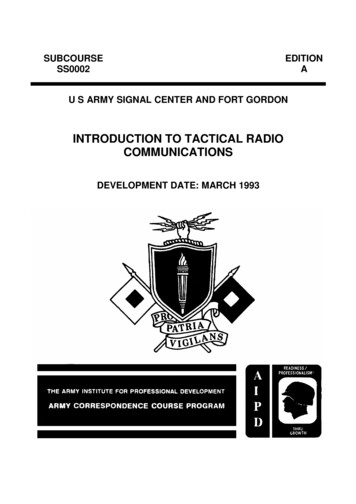
1.4Standard Kit Parts Illustration:The illustration below is provided for quick identification of thestandard parts of the ATILLA-200 kit.Figure 1-1 Standard Kit Parts IllustrationNivisys, LLC. Rev. 16 July 20121-3
1.5System Performance and Data:The table below lists the technical specifications and data of theATILLA-200 system. The data contained herein is subject tochange without notice.ITEMLIMITSElectricalPower source3.6 VDC MaxBattery Type1 .5V AA - 2eaAA 1 .5V LithiumBattery life8.5 hours @ 23º CPhysicalLength X Width X Height5 .25 x 2.5 x 1.5 inchesWeight w/ batteries7.5 ounces (215g)EnvironmentalShock ResistanceWeapons up to 0.50 calStorage Temp. Range-57ºC to 71ºCOperation Temp. Range-32ºC to 51ºCAimerWavelength Peak830nmSlow Blink Rate1HzFast Blink Rate2HzBeam Divergence (FWHM)0.3mR min.Table 1-3 System Performance and DataNivisys, LLC. Rev. 16 July 20121-4
ITEMLIMITSAimer (cont.)Optical Output, High Power(Black paddle/remote)50mW @ 23º COptical Output, Eye-safe(Blue paddle/remote)0.64mW @ 23º CBeam Range, High Power(Black paddle/remote)20,000m (Using GEN IIINight Vision Device)Beam Range, Eye-safe(Blue paddle/remote)3,000m (Using GEN IIINight Vision Device)Windage/Elevation Adjustments0.4 mR/clickAdjustment Range54mR total travelIlluminatorWavelength Peak830nmBeam Divergence (FWHM)1.0mR-240mR (13º)Optical Output, High Power(Black paddle/remote)150mW @ 23º COptical Output, Eye-safe(Blue paddle/remote)2.5mW @ 23º CRange15,000-2,000m (Using GEN IIINightVision Device)Windage/Elevation Adjustments0.4 mR/clickAdjustment Range54mR total travelTable 1-3 System Performance and Data, (cont.)Nivisys, LLC. Rev. 16 July 20121-5
1.6Nominal Ocular Hazard Distance (NOHD)The distance at which beam irradiance or radiant exposurebecomes equal to the maximum allowable exposure on thecornea. Care must be taken against laser exposure within thisdistance. However, it does not mean that continuously lookingat the laser beam at a distance longer than NOHD is safe or hasno hazardous influence.NOHD Summary for the ATILLA-200 SeriesNOHDType of 83m)5 cm optics (7x50binoculars)949yds(868m)1818yds(1662m)8 cm optics (Tanks)1506yds(1377km)2870yds(2624km)12 cm optics (Big Eyes)2240yds(2048km)4238yds(3875km)Table 1-4 NOHD SummaryNivisys, LLC. Rev. 16 July 20121-6
CHAPTER 2:PREPARATION FOR USE2.1Introduction:This section contains instructions for installing components tothe ATILLA-200 and general preparation for operation undernormal conditions.2.2 Battery Precautions:WARNINGDo not mix alkaline and lithiumbatteries. Do not mix old and newbatteries. Do not mix brands ofbatteries. do not mix disposable andrechargeable batteries. Failure tofollow these instructions could resultin death, injury or imposition of longterm health hazards.WarningInspect batteries for bulging priorto use. If the battery shows signs ofbulging, do not use.WarningDO NOT HEAT, PUNCTURE, DISASSEMBLE,SHORT CIRCUIT, Incinerate, ATTEMPT TORECHARGE OR OTHERWISE TAMPER WITH THEBATTERIES. TURN OFF the ATILLA-200 IF theBATTERY COMPARTMENT BECOMES UNDULYHOT. IF POSSIBLE, WAIT UNTIL THE BATTERIESHAVE COOLED BEFORE REMOVING THEM.Nivisys, LLC. Rev. 16 July 20122-1
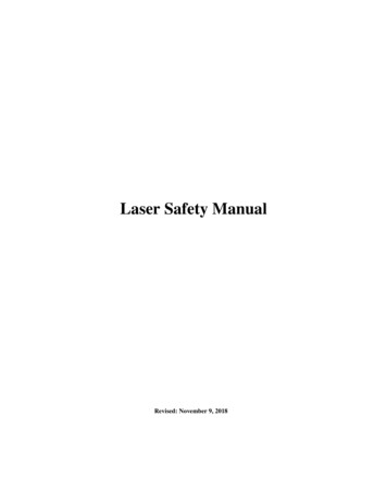
CAUTIONObey the battery manufacturer’sdirections for battery disposal.2.3 Battery Installation:The ATILLA-200 electronic circuit is powered by two (2)Lithium AA batteries. Install the batteries as follows.1. Remove the battery cap by turning it counter-clockwise.2. Check to ensure the o-ring is present and undamaged.Replace o-ring if necessary.3. Insert batteries into the battery compartment, positive ( )ends first, negative (-) ends toward the battery cap.4. Replace battery cap, turning it clockwise until a secure.o-ringbattery capFigure 2-1 Battery Installation2.4NVEC #16 Weapon Mount Assembly Installationon an M16:The ATILLA-200 is configured to attach to a MIL-STD-1913rail system. The standard ATILLA-200 kit includes theNVEC#16 Weapon Mount Assembly, which is a mount thatNivisys, LLC. Rev. 16 July 20122-2
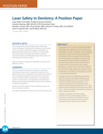
can be attached to a M16 style gun. To install the NVEC#16perform the following.1. Place spacer “A” between gas tube and barrel.2. Place upper clamp “B” between spacer tube and barrel.DBACIFigure 2-2 NVEC#16 Installation, Steps 1-6 ExplodedNivisys, LLC. Rev. 16 July 20122-3
3. Place lower clamp “C” under barrel and align the holes in theupper and lower clamps.4. Place mount body “D” over gas tube and align holes with theclamp holes (spacer “A” fits into slot on mount body “D”).5. Install #6 screws and washers (I).6. With screws loose, slide assembly forward to the stop snugscrews but DO NOT TIGHTEN FURTHER.Figure 2-3 NVEC#16 Installation, Steps 1-6 Completed7. Replace hand guard “H” and rail “E” over mount posts “F.”8. Install and tighten flat head screws “G”.GEHFFigure 2-4 NVEC#16 Installation, Steps 7-8 ExplodedNivisys, LLC. Rev. 16 July 20122-4
9. Tighten screws “I”.iFigure 2-5 NVEC#16 Installation, Step 910.Install hand guard “J”.JFigure 2-6 NVEC#16 Installation, Step 102.5Attaching to a MIL-STD-1913:WarningMake sure the weapon is clear and onsafe before proceeding.1. Open the levers of the mount perpendicular to the length ofNivisys, LLC. Rev. 16 July 20122-5
the ATILLA-200.2. Place the ATILLA-200 on the MIL-STD-1913 rail system ofthe weapon.3. Ensure that the mount is seated squarely on the rail.4. Close the levers of the mount in line with the length of theATILLA-200.leverS CLOSEDFigure 2-7 Weapon Mount Installation2.6Remote or Paddle Switch Installation:The ATILLA-200 comes with two types of switches to be usedto fire the laser.SwitchDescriptionBlackPaddleHigh power, local controlRemoteHigh power, remote controlBluePaddleEye-safe power, local controlRemoteEye-safe power, remotecontrolTable 2-1 Switch DescriptionNivisys, LLC. Rev. 16 July 20122-6
Both the remote an the paddle switch are installed using thesame method. To install a remote or paddle switch into theATILLA-200 perform the following.1. Locate the remote/paddle switch that will be used. Note thetwo tabs with metal strips on one side.2. Identify the switch receptacle on the ATILLA-200 locatedunder the windage and elevation adjusters.3. Ensure that the switch receptacle is free and clear of moistureand dirt.4. Insert the tabs of the remote/paddle switch into the ATILLA200 switch receptacle.5. Ensure that the switch is fully seated into the switchreceptacle.NoteTHE remote/paddle switch can only beinserted in one orientation.TABSSWITCHRECEPTACLEREMOTESWITCHFigure 2-8 Remote/Paddle Switch InstallationNivisys, LLC. Rev. 16 July 20122-7
paddleSWITCHREMOTESWITCHFigure 2-9 Paddle and Remote SwitchesNivisys, LLC. Rev. 16 July 20122-8
CHAPTER 3:OPERATIng instructions3.1Introduction:This chapter contains instructions for the safe operation of theATILLA-200 under normal circumstances and environments.3.2Operating Precautions:WARNINGThere are eye and other hazardsassociated with the use of theATILLA-200 Series. Safe operation of thisproduct requires following Warnings,Cautions and Notes contained in thisOperator Manual.WARNINGA Laser Safety Officer (LSO) should beassigned to support operational andtraining activities using the ATILLA-200.The LSO should be adequately trainedand provide training IAW ANSI Z136.1-2007(or latest version).WARNINGAll personnel participating in trainingor operations that involve the use oflasers should comply with Command /Organizational Unit and LSO guidance.Nivisys, LLC. Rev. 16 July 20123-1
WARNINGIt is necessary and intended thatLaser Eye Protection or Night VisionDEVICES be worn by the operator whenoperating, maintaining, servicing, ortesting the ATILLA-200.WARNINGWhen in hoStile territory, operate theATILLA-200 with caution. Any personusing night vision devices can detectthe IR source used in the ATILLA-200.WARNINGNever view the beam directly on axis.Observe all nominal ocular hazarddistance (NOHD).WARNINGUse of controls, adjustments orperformance of procedures other thanthose specificed herein may result inhazardous radiation exposure.Nivisys, LLC. Rev. 16 July 20123-2
3.3 Controls and Indicators:The controls and indicators for the ATILLA-200 are shown inFigure 3-1 and are described in Table 3-1.Figure 3-1 Controls and IndicatorsNivisys, LLC. Rev. 16 July 20123-3
Control andIndicatorsFunctionsContinuous FireButtonThe continuous fire button allows foruninterrupted firing of the aimer and illuminator.Illuminator/Aimer PowerAdjustmentSeparate UP and DOWN arrows for adjusting thebeam intensity of both the laser and illuminator.Aiming LaserAdjustersAn elevation (EL) and azimuth (AZ) adjustmentknob on top and the side of the unit is used toadjust the aimer during the zeroing process.IlluminatingLaserAdjustersAn elevation (EL) and azimuth (AZ) adjustmentknob on top and the side of the unit is used toadjust the aim of the illuminator.Continuous FireON IndicatorIlluminates a red LED when the Laser is ON.Low BatteryIndicatorFlashes when the ATILLA battery power is low.Remote orPaddle SwitchWhen installed, the paddle or remote switch isused to momentarily fire.IlluminationLaser FocusKnobAdjusts the spread or beam divergence of theilluminator.OFF/ModeSwitch KnobControls the different modes of beam output.Table 3-1 Controls and IndicatorsNivisys, LLC. Rev. 16 July 20123-4
3.4Safe Operation:Once the batteries are installed, do not point the laser towardany person within the NOHD. Night vision goggles willprovide protection by blocking the laser beam from directlyentering the eye but the goggles themselves may be damaged.Other than the enemy, do not intentionally illuminate anyonewith or without NVG within the NOHD, whether duringoperations or training. Refer to the section 1.6 for NOHDdistances.WARNINGNever view the beam directly on axis.Observe all nominal ocular hazarddistance (NOHD).(The NOHD for the ATILLA-200 Series islisted in 1.6.WARNINGDo not point the laser at specular (i.e.mirror-like) surfaces.3.5Powering ON the ATILLA-200:The OFF/Mode switch knob must be turned to one of the fourbeam modes in order for the laser to fire. A beam mode isselected as its marking is aligned with the mode indicator boss.Rotate the OFF/Mode switch knob clockwise to activate any ofthe four beam modes.Nivisys, LLC. Rev. 16 July 20123-5
MODEINDICATORBossOFF/ModeSwitchknobFigure 3-2 OFF/MODE Switch Knob3.6 Beam Modes:The ATILLA-200 features 5 different modes for beam output.To adjust the beam mode, turn the OFF/MODE switch knobclockwise from the OFF position. The switch will give audioand tactile feedback as each mode is selected. To ensure aspecific mode, turn the OFF/MODE switch until the selectionindicator boss is in line with the printed mode icon.The five printed mode icons are explained in the followingtable.ATILLA-200 BEAM MODESMode IconDescriptionON- SteadyON- Slow Pulse, 1HzON- Fast Pulse, 2HzTable 3-2 Beam ModesNivisys, LLC. Rev. 16 July 20123-6
ON-Steady, with IlluminatorON-Slow Pulse, with IlluminatorTable 3-2 Beam Modes3.7 Firing the Laser Using the Continuous Fire Button:Once a beam mode is selected using the OFF/Mode switchknob, the ATILLA-200 can be fired by pressing the continuousfire button located on the top of the unit. To fire the ATILLA200 using the continuous fire button perform the followingprocedure.1. Turn the OFF/MODE switch knob in a clockwise direction toselect a beam mode.2. Press and hold the button for one second to turn ON thecontinuous aimer/illuminator beam output.3. Press the button again to turn OFF the continuous aimer/illuminator beam output.CONTINUOUSFIRE BUTTONFigure 3-3 Continuous Fire ButtonNivisys, LLC. Rev. 16 July 20123-7
NOTETHE OFF/MODE Switch knob must beturned to one of the 5 beam modes inorder for the Continuous fire to beactivated.WARNINGWhen Continuous fire is activated, theOFF/MODE switch knob controls thelaser fire until the continuous firebutton is pressed again.3.8 Firing the Laser Using the Remote or Paddle Switch:The ATILLA-200 can also be fired by a momentary fire buttonlocated on the remote or paddle switch. The aimer/illuminatorwill only fire as long as it is depressed. To fire the ATILLA200 using the remote or paddle switch perform the followingprocedure.1. Ensure the paddle or remote switch is correctly installed.2. Ensure that continuous fire is not activated.3. Turn the OFF/MODE switch knob in a clockwise direction toselect a beam mode.4. Press the momentary fire button of the installed switch.NOTEThe use of Continuous fire BUTTON(indicated by a RED LED) overrides anyoperation of the remote or paddleswitch.Nivisys, LLC. Rev. 16 July 20123-8
RemoteswitchPADDLEswitchMomentaryFIREBUTTONFigure 3-4 Momentary Fire Button3.9 Continuous Fire (CF) Indicator:The ATILLA-200 is an invisible aimer/illuminator. A visibleLED glows red when continuous fire button is active and theOFF/Mode switch knob is turned to one of the 5 beam modes.NOTEThe CF indicator does not glow redduring use of the paddle or remoteswitch.CONTINUOUSFIRE ONindicatorFigure 3-5 Continuous Fire IndicatorNivisys, LLC. Rev. 16 July 20123-9
3.10Low Battery Indicator:The ATILLA-200 is equipped with a visible LED that flashesred when the battery power is low. The low battery indicatorwill be a steady glow during laser fire.LOW BATTERYindicatorFigure 3-6 Low Battery Indicator3.11Power Adjustment Buttons:The power adjustment buttons are used to adjust output powerof the aimer and illuminator beams. Power output can beadjusted to optimize target and scene visibility. The aimerpower adjustment buttons are located in line with the laser beamicon and the illuminator adjuster buttons are located in line withlight bulb icon.To adjust the aimer or illuminator power in small incrementsperform the following procedure.1. Activate continuous laser fire or press the momentary firebutton on the installed remote or paddle switch.2. Increase power by pressing the arrows above the laser andlight bulb icons.3. Decrease power by pressing the arrows below the laser andlight bulb icons.NotePower adjustments can also be made bypressing and holding the poweradjuster buttons.Nivisys, LLC. Rev. 16 July 20123-10
ATILLA-200 Power SettingsFireButtonUsedAiming BeamIlluminatorMin PowerMax PowerMin PowerMax PowerContinuousFire ButtonEye-safelessthan 0.1mWEye-safelessthan 0.7mWEye-safe3.2mWEye-safe3.2mWBluepaddleor remoteswitchEye-safeless than0.15mWEye-safeless than0.7mWEye-safe0.6mWEye-safe3.2mWBlackpaddleor le 3-3 ATILLA-200 Power SettingsIncreasepowerdecreasepowerFigure 3-7 Power Adjustment ButtonsNivisys, LLC. Rev. 16 July 20123-11
3.12Illumination Laser Focus Knob:Rotating the illumination laser focus knob adjusts illuminatordivergence angle from 1mR to 240mR. The focus adjustmentcan be rotated continuously in either direction without damageto the ATILLA-200.illuminatORfocus knobFigure 3-8 Illuminator Focus Knob3.13Elevation and Azimuth Adjusters:The ATILLA-200 contains a set of elevation and azimuthadjusters for both the aimer and illuminator for use of zeroingthe beam (dot) position relative to the bullet strike. One clickmoves the Mean Point of Impact (MPI) 0.4mR in the directionindicated for the aiming laser and 0.4mR for the illuminator.Nivisys, LLC. Rev. 16 July 20123-12
Figure 3-9 Elevation and Azimuth Adjusters3.14Preparing the ATILLA-200 for Zeroing:This manual contains a comprehensive zero procedure to alignthe beam of the ATILLA-200 to the point of impact of the bullet.It is recommended that the aim dot and the point of impact notbe coincident but that they be offset on the boresight or zeroingtarget in the same relationship as they are mounted on theweapon. This will ensure the same aiming point to bullet strikerelationship at all engagement ranges. To zero the ATILLA-200to the weapon perform the following.1. Install the ATILLA-200 onto the weapon rail with appropriatemomentary switch.NoteWhen Reinstalling The ATILLA-200 tothe weapon, be sure to return it to theexact rail location for an accuratezero to weapon.Nivisys, LLC. Rev. 16 July 20123-13
2. Set the power adjustment knob to its lowest setting.3. Achieve a neutral adjustment setting by turning each adjusterclockwise until a stop occurs. Return the adjuster knobsapproximately three rotations counter-clockwise until thewhite dot on the adjuster knob is forward (toward the MPImarking on the adjuster flange).White DotFigure 3-10 Neutral Adjustment SettingCAUTIONTo prevent jamming the adjustmentknobs, do not force the adjusters torotate past their end of travel.CAUTIONDo not use tools to turn adjusterknob.Nivisys, LLC. Rev. 16 July 20123-14
3.15 Zeroing the ATILLA-200 to a M16/M4 using the NVEC#16:The equipment listed below is required to perform the followingprocedure. M16/M4 rifle with NVEC#16 mount installed ATILLA-200 aiming light kit Stand or flat area to secure target (wall, clipboard, etc.) Weapons vise, sand bags or clamp Laser boresight with proper size bore mandrel Night vision system with day light cover 10m boresight target (TARATL10) 82ft (25m) space away from personnel.NOTEUse the full size target supplied withthe ATILLA-200 kit when performing thefollowing zeroing procedure.TARATL10 Rev. 18 APR 11Laser BorelightGrids are 1cm wide by 1cm high.Zero Target Data for M16/M4 with NVEC#16 installed:1. Stabilize Weapon.2. Align Laser Boresight on it’s dot.3. Adjust until aiming laser is centered on the dot cross hair.AimerIlluminatorFigure 3-11 Example Target for Zeroing Using the NVEC#1610m Boresight Target for 150m ZeroNivisys, LLC. Rev. 16 July 20123-15
1. Mount the ATILLA-200 on the weapon.2. Place the target on flat area at 33ft (10 m) from the weaponposition. Target area should be out of direct bright light, anindoor location is best.3. Lock the weapon in a weapon vise, clamp or stabilize it withsand bags pointing in the direction of the target (CRITICAL).4. With the proper size mandrel, insert a laser boresight in thebarrel in accordance with laser boresight instructions.5. Adjust the weapon and/or target position to project the laserboresight beam to the laser boresight position on the target.6. Station a night vision equipped assistant near the target,WITH BACK TOWARDS IR LASER APERTURE.CAUTIOnKEEP DAYLIGHT COVER ON TO AVOID DAMAGETO NIGHT VISION DEVICE.7. Fire the ATILLA-200 aimer and have night vision equippedassistant provide directions to person at the weapon to adjustATILLA-200 beam (elevation and azimuth). The targetprovided shows aimer and illuminator aim points for theATILLA-200 mounted at the 12 o’clock, 3 o’clock, 6 o’clockand 9 o’clock rail positions.CAUTIONNight vision device should only beturned on long enough to mark thepaper.8. ATILLA-200 aimer is boresight zeroed when aimer is in thecircle of the ATILLA-200 laser box crosshair on the target.9. Repeat steps 7 and 8 to boresight the illuminator.Nivisys, LLC. Rev. 16 July 20123-16
warningLive fire zeroing is recommended todetermine exact placement at knowndistances.NOTEThe ATILLA-200 will retain zero after ithas been removed and replaced on thesame weapon in the same slot on theNVEC#16.WARNINGTHE ATILLA-200 it must bere-zeroed whenever the mounting (base)bracket is removed from the ATILLA-200and replaced.3.16 Zeroing the ATILLA-200 to Any Weapon:After performing the dry boresighting of the ATILLA-200 serieslaser aimer to the weapon bore, it is recommended to conducta live fire boresight at the 150m designated zero range. Theprocedure is as follows:1. Arrange a target at 150m range downrange.2. Adopt a secure and stable firing position.3. Don night vision goggles and switch ON.4. Activate the ATILLA-200 laser and bring the laser dot ontotarget center.5. Fire a group of 5 rounds, single shot, maintaining a steadyaim on the target center6. Clear weapon and switch to SAFETY.7. Check impact position of 5 rounds on the target, determinethe center of the shot group, or mean point of impact (MPI).8. If any adjustments are necessary, use the following table forMPI adjustments at 150m range:Nivisys, LLC. Rev. 16 July 20123-17
AzimuthDirection to moveadjusterMovement per clickClockwisemoves MPI downElevationClockwisemoves MPI right6cm (2.4in) at 150mTable 3-4 Live Fire Adjustments at 150m9. Repeat steps 2 through 8 until the center of the shot group islocate
pulsing modes. The ATILLA-200 is for use with night vision devices and can be used as either a handheld aimer/illuminator or can be weapon mounted In the weapon mounted mode, the ATILLA-200 can be used to accurately direct fire as well as to illuminate and designate targets. The ATILLA-200