Transcription
TWEAKER USER MANUALWWW.ELECTRIXPRO.COM
ELECTRIX TWEAKER User ManualTable of Contents123456Getting Started1.1Introduction1.2What‘s Included in the Box?1.3Product Registration1.4Height Extension Legs1.5Overlay Installation1.6Firmware & UtilitiesConnections2.1USB2.2MIDI In2.3MIDI OutHardware Controls3.1Buttons3.2Encoders3.3LED’s (Button Indicators)3.4LED Rings3.5Pressure Sensitive Pads3.6PotentiometersDefault MIDI SettingsThe Settings Channel5.1Encoder Settings5.2LED Ring SettingsSysEx Messages6.1System Exclusive Command Bytes244455568888991113151819222455283232
ELECTRIX TWEAKER User Manual6.26.36.4Set MessagesRequest ResponsesMessage Glossary323940Safety Instructionsliquid has been spilled or objects have fallen into theapparatus, the apparatus has been exposed to rainor moisture, does not operate normally, or has beendropped.Read these instructions. Keep these instructions.Heed all warnings. Follow all instructions. Do not usethe apparatus near water. Clean only with dry cloth.Use in accordance with the manufacturer’sinstructions. Do not use near any heat sources suchas radiators, heat registers, stoves, or other apparatus(including amplifiers) that produce heat.Please keep the unit in a well ventilated environment.WARNINGTo reduce the risk of fire or electric shock, do notexpose this apparatus to rain or moisture. Theapparatus shall not be exposed to dripping orsplashing and that no objects filled with liquids, suchas vases, shall be placed on the apparatus.Protect the USB cord from being walked on or pinchedparticularly at plugs, convenience receptacles, andthe point where they exit from the apparatus.Only use attachments/ accessories specified by themanufacturer.CAUTIONTo reduce the risk of electric shock, do not removeany cover. No user-serviceable parts inside. Referservicing to qualified service personnel only.Refer all servicing to qualified service personnel.Servicing is required when the apparatus has beendamaged in any way, such as damaged connectors,3
1. Getting Started1 Getting StartedThank you for purchasing the TWEAKER on behalf of the entire Electrix team. We hope you enjoyperforming with the TWEAKER as much as we enjoyed making it!1.1 IntroductionTWEAKER is a universal controller that offers lots of options for customization, but for those whowant to get started right away, we included mappings and overlays for popular programs likeTraktor and Ableton.For those of you who like to dig a little deeper, the included TWEAKER EDITOR lets you customizesettings and save your own presets for use with a variety of software applications. This manual alsocontains lots of useful information on default settings, SysEx used by TWEAKER, and the SettingsChannel, which is used to send MIDI messages back to TWEAKER to change settings on-the-fly.4
1. Getting Started1.2 What’s Included in the Box?The TWEAKER box contains the following items:The TWEAKER ControllerA set of four height-extension legsA USB cableA Quick Start posterAn installation CD including: Traktor 2 LE, TWEAKER EDITOR software,and the Ableton Live Remote Script8 An overlay for the included Traktor 2 LE software8 An overlay for the included Ableton Live Remote Script888881.3 Product RegistrationWhy not take a few minutes to register your new product? Registration enables us to keep a recordof your product in case you ever need assistance or warranty coverage. It also enables us to keepyou up to date on any software or firmware updates, availability of new mappings or overlays, etc.In some cases, additional content may also be available for registered users.To register your product, visit www.electrixpro.com and click on the Register/Login link at the rightcorner of the site.1.4 Height Extension LegsA set of four legs is included to extend the height of the TWEAKER to match traditional DJ gear. Withthe legs installed, TWEAKER is the same height as most DJ turntables. The legs screw directly intothe bottom surface of the TWEAKER using the provided screw-holes.1.5 Overlay InstallationTo place an overlay on the TWEAKER, simply remove the three fader knobs and place the overlayon the face plate, making sure that it is tightly fitted in the corners and around all the controls.5
1. Getting StartedThe TWEAKER enclosure was designed to keep overlays in place with minimal movement duringperformances.1.6 Firmware & UtilitiesThe TWEAKER’s firmware updates via USB. Firmware updates may become available from time totime. Visit www.electrixpro.com to register your product and sign up to receive TWEAKER updates.1.6.1 Checking Current Firmware VersionYou can check your current firmware version at any time by holding the three buttons downindicated on the image below, simultaneously:While these three buttons are held down, the firmware version will be indicated on the bottomencoder LED rings on both mixer channels. The left LED ring indicates the number before thedecimal point, and the right LED ring indicates the number after the decimal point. For example,to indicate version 4.3, four LED’s will light up on the left ring, and three LED’s will light up on theright ring.6
1. Getting Started1.6.2 Updating Firmware1. Hold down the round rubber button located in the center of the four directional navigationbuttons, while connecting Tweaker to your computer,2. A volume named TweakerDisk will mount on your system,3. Drag the Tweaker firmware binary file and drop it onto the TweakerDisk volume,4. The velocity pads will flash while the firmware is updating. Do not disconnect the USB cableduring this process,5. It is safe to disconnect the USB once the pads have stopped flashing. Once the update iscomplete you must reconnect the TWEAKER to return to normal operating mode.1.6.3 LED TestTo test the LED’s, hold down button the large navigation encoder push button while connectingTweaker to your computer. All LED’s will light up. Press it again to exit and return to normal operatingmode.7
2. Connections2 ConnectionsAny of the controls on TWEAKER can be configured to provide a wide range of functionality. Hereare some basic terms and uses for the controls.2.1 USBThe USB port connects to your computer to send and receive MIDI message, update the firmware,and power the unit. This port is available to your software as Tweaker Port 1.2.2 MIDI InThe MIDI Input port provides a standard 5 PIN MIDI jack to connect other MIDI devices to TWEAKER.MIDI input data is then routed over USB to the host computer, and is available to your software onthe second port named “Tweaker Port 2.”2.3 MIDI OutThe MIDI Output port provides a standard 5 PIN MIDI jack for outputting MIDI from your computer,over the USB cable, and to the MIDI jack. TWEAKER will also send its data from the MIDI Out jack. ThisMIDI Output can be accessed on your computer via the port named “Tweaker Port 2.”8
3. Hardware Controls3 Hardware ControlsAny of the controls on the TWEAKER can be configured to provide a wide range of functionality.Here are some basic terms and uses for the controls.3.1 ButtonsThe TWEAKER has 7 encoder push buttons and 43 custom-designed, soft-touch rubber buttons.All button parameters can be controlled using the TWEAKER EDITOR software. The specific MIDImessages that the TWEAKER recognizes are also detailed below.Most music programs are designed to use momentary buttons. For this reason, the TWEAKER’sbuttons are momentary: they send a Note On message when pressed, and a Note Off messagewhen released. This is similar to the way piano keys operate.9
3. Hardware Controls3.1.2 MappabilityEach button can be mapped to output Notes or CC’s. Each button may also function as a speedcontrol button for the encoders (detailed below). The assignment of each button may be modifiedusing the TWEAKER EDITOR or the ‘Set Button Mapping’ SysEx.Note/ CCEach button can be mapped to any note (0-127) and any CC (0-119). Multiple buttons can bemapped to output to the same Note/ CC, but only one indicator LED can receive feedback on thatNote/CC. Each button has its own individual output channel.The TWEAKER outputs a 127 ‘ON’ and 0 ‘OFF’ velocity when mapped as a Note or a CC.Default SettingsSoft-touch buttons are mapped to Notes 1-43Encoder push buttons are mapped to Notes 44-50All buttons operate on MIDI Channel 1Speed Control ButtonThe TWEAKER’s encoders are capable of increasing or decreasing their value at 2 assignableencoder speeds. Any button may be mapped as a ‘Speed Control Button’ to toggle between thesetwo speeds. By default, the encoders increase values at about the same rate as a potentiometer,and a little over a 3/4 turn achieves a full MIDI range of 0-127. This is encoder speed ‘5’. When youswitch to the default alternate speed for fine control with the speed control button, each click ofthe encoder increments one value. At this speed, you need four full turns of the encoder to achievea full MIDI range of 0-127.3.1.3 LED FeedbackAll of the TWEAKER’s rubber buttons and pads are backlit by LED’s. Each LED can be controlled byits respective button’s current state (on/off ). By default, Button Local Control of LED’s is disabledbecause it can interfere with software MIDI feedback.All button indicator LED’s can also be controlled by incoming MIDI Messages. By default, all buttonindicator LED’s have the same mapping as their respective buttons. This makes TWEAKER compatiblewith most music software that use MIDI feedback by default.10
3. Hardware Controls3.2 EncodersThe TWEAKER has 7 encoders. Each encoder is capable of outputting in Absolute or Relative Mode.The output mode of each encoder can be adjusted using the TWEAKER EDITOR, the SettingsChannel, or using the “Set Encoder Output Modes” SysEx.3.2.1 Absolute ModeWhen in Absolute Mode, an encoder outputs very much like an ordinary potentiometer. By default,the six channel strip encoders are in Absolute Mode. Absolute mode is generally used to controleffects, EQ settings, and other continuous parameters. As you turn clock-wise, the encoder willoutput increasing values until it outputs 127. As you turn counter clock-wise, the encoder willoutput decreasing values until it outputs 0. If Local Control of the LED rings in is enabled, the ringwill update the display the current value of the encoder.Local Control for encoders in Absolute Mode can be controlled using the TWEAKER EDITOR or theRing Local Control feature of the Settings Channel.Encoder SpeedsThe angle of turn needed to complete a full 0-127 sweep on an encoder is dependent on thedeclared encoder speed. This is a global control. The default speed is 5, and the default alternatespeed is 1. At a Speed of 5, the Encoder changes value at about the same rate as a potentiometer.At a Speed of 1, the encoder’s natural speed, an encoder changes value at 1 value per encoderclick/detent (about one quarter of the rate of a potentiometer). Maximum Encoder Speed is 7, andMinimum Speed is 1. The TWEAKER stores 2 encoder speeds at a time, and they can be toggledbetween using a Speed Control Button.11
3. Hardware ControlsEncoder speeds are assignable by the TWEAKER EDITOR’s “encspeedA” and “encspeedB” functions,by sending a message to an encoder on the Settings Channel, or using the “Set Encoder Speeds”SysEx Message.MIDI FeedbackEncoders in Absolute Mode accept standard MIDI Feedback. If the TWEAKER receives a messagewith the same mapping as an encoder, it will use the value of that message to set the current valueof the encoder.For example, If the message “CC57, value 127, on Channel 1” is received by a TWEAKER with defaultsettings, it will update its stored value for the top-left encoder to 127. If Ring Local Control is enabled,the LED Ring will update the display the current value of the encoder.MIDI Feedback LoopsIn order to eliminate feedback loops that could lock an encoder at a value, the TWEAKER willignore a MIDI message that is mapped to an encoder that is actively being turned by the user. Thisis especially helpful for TRAKTOR’s feedback system, which will send a message right back to theTWEAKER after receiving it in some cases. The TWEAKER can still accept messages that are mappedto the LED Ring that accompanies that encoder during this period if Ring Local Control for encodersin Absolute Mode is disabled.3.2.2 RelativeThe TWEAKER’s encoders can also operate in Relative Mode. This version of relative mode is knownas “2’s Compliment.” When in Relative Mode, an encoder outputs continuously in either direction.Relative Mode is generally used to cycle through long lists, adjust track position, and otherincremental adjustments that require more than the traditional 0-127 output. By default, the largenavigation encoder is in Relative Mode.The TWEAKER only outputs two messages in Relative Mode:8 Clockwise: 1 ( velocity/ value 1 )8 Counter-Clockwise: -1 ( velocity/ value 127 )One message is output for each click of the encoder (increment or decrement). There areapproximately 30 increments in one full rotation of an encoder. If Ring Local Control in RelativeMode is enabled, the LED Ring will update to show the direction of the encoder’s last turn.Ring Local Control in Relative Mode can be controlled using the Local Control feature of the SettingsChannel.12
3. Hardware ControlsMIDI FeedbackEncoders in Relative Mode are capable of accepting MIDI feedback to the LED Rings. If the TWEAKERreceives a message with the same mapping as an LED Ring, the TWEAKER will use that message toset the current display of the LED Ring based on the LED Ring’s Display Mode and the value of themessage.If Ring Local Control in Relative Mode is disabled, software applications capable of sending scaledfeedback to one of these LED rings can display absolute-style feedback to your TWEAKER forcontrols that you are modifying with an encoder in Relative Mode.3.2.3 MappabilityNote/ CC MessagesEach encoder can be mapped to output to any CC (0-119) using the TWEAKER EDITOR or the “SetEncoder Mappings” SysEx. Multiple encoders can be mapped to output to the same Note/ CC, butonly one will be able to receive direct feedback via MIDI message in this case. Each encoder has it’sown individual output channel that can be changed using the TWEAKER EDITOR.3.3 LED’s (Button Indicators)The TWEAKER has a total of 57 button indicator LED’s: 38 RGB LED’s, 13 red monochrome LED’s, and6 blue monochrome LED’s for the encoder push buttons.3.3.1 Reception ModesThe LED’s are capable of responding to Note / CC MIDI messages as well as button presses.Note/ CCLED mappings follow the mapping of the corresponding buttons or pads. By remapping thematched button or pad, each LED can be mapped to respond to any Note (0-127) and any CC (0115) using the TWEAKER EDITOR or the “Map Buttons” SysEx Messages.Each RGB LED has it’s own individual reception channel and mapping, which is independent ofthe button mapping. Each monochrome LED shares its individual reception channel with thecorresponding button.13
3. Hardware ControlsDefault Settings88888The RGB LED’s are mapped to Notes 1-38The Red LED’s used for the navigation style buttons are mapped to Notes 39-43.The Red LED’s used for pressure sensitive pads are mapped to Notes 63-70.The Blue LED’s to indicate encoder push button activity are mapped to Notes 45-50.All LED’s are mapped to MIDI Channel 1Button Local ControlThese Button Indicator LED’s can also be locally controlled. In other words, they can light in reactionto a Button’s Current State, but only if the Button Local Control is enabled for the Button.Button Local Control can be turned on and off in the TWEAKER EDITOR’s Global Settings, or by CCMessage using the ‘Local Control’ feature of the Settings Channel (See Chapter 6 for details).14
3. Hardware Controls3.3.2 Display StylesRGB LED’sThere are 38 RGB (Red/Green/Blue) LED’s: 32 for the grid and three per channel strip. They haveeight states:8 000-000: Off8 001-003: Green8 004-007: Red8 008-015: Yellow8 016-031: Blue8 032-063: Cyan8 064-126: Magenta8 127-127: WhiteMonochromatic LED’sThere are 13 red monochrome LED’s and 6 blue monochrome LED’s. They have two states:8 000-063: LED Turns Off8 064-127: LED Turns Solid On3.4 LED RingsThere are three LED rings per mixer channel strip. Each LED Ring is composed of 13 red LED’s.3.4.1 Reception ModesAn LED ring’s display can be controlled by incoming Note / CC MIDI messages and the by theencoder it surrounds.By default, encoders are in Absolute Mode, and the LED rings display the current value of theencoder. An LED ring also updates when the TWEAKER receives a MIDI message that matches itsmapping.Note/ CC MessagesLED Ring mappings can be modified using the TWEAKER EDITOR, or the “Set LED Ring Map” SysExmessage. When the TWEAKER receives an LED ring-directed message, the LED ring is updated asdetermined by its display mode and message velocity/value. These messages do not affect the15
3. Hardware Controlsencoder value.Default SettingsThe LED Rings are mapped to CC79-84 on MIDI Channel 1.Encoder Local ControlBy default, the LED rings are locally controlled by the encoders. Locally controlled encoders canupdate the LED rings when:8 User turns the encoder, or8 TWEAKER receives a MIDI message (also known as a feedback message) that matches themapping of the encoder.3.4.2 Display ModesThe LED rings have four modes to accurately display the current state of any function. The displaymode of each LED ring can be set using the TWEAKER EDITOR, by using the “Set LED Display Mode”SysEx, or by basic Note / CC Messages, using the LED rings feature of the Settings Channel.WalkWalk mode lights 1 LED at a time and seemingly walks up as encoder’s value increases. This modehas 14 states, so the visual resolution of each state is about 9 MIDI values.FillFill mode lights all preceding LED’s as encoder’s value increases. This Mode has 14 States, so thevisual resolution of each state is about 9 MIDI values.16
3. Hardware ControlsEQEQ mode lights from the center LED and stretches either to the left or right depending on the LEDring’s display value. When the LED ring’s display value reaches 0, the LED’s on the left side will all belit. When the LED ring’s display value reaches 127, the LED’s on the right side will all be lit. This modehas 13 states, so the visual resolution of each state is about 10 MIDI Values. This mode is good forparameters that are centered around MIDI value 63-64, such as EQ and pan.By default, the LED rings are in EQ mode.SpreadSpread mode lights the rings from the center LED out to both edges. This Mode has 8 states, so thevisual resolution of each state is about 15 MIDI Values. This display mode is especially effective forresonance (width) controls of parametric EQ’s.RelativeRelative Mode is used only for relative encoder local control, and cannot be specially assigned.It has five states; still, incrementing, incrementing (alternate), decrementing, and decrementing(alternate).Dual DisplayLED rings are capable of responding to incoming MIDI messages, and being controlled by encodermovements at the same time. You may, for example, have your software stream the current track’soutput level on CC79 (the top-left LED Ring). You may also have that encoder at CC57 controlling thefader volume for the track. In this example, when you turn the encoder, the LED ring will temporarilyallow the encoder value to display on the LED ring. When you finish turning, the TWEAKER willrelease the control of the LED ring back to the MIDI stream of the current track’s level.17
3. Hardware Controls3.5 Pressure Sensitive PadsThe TWEAKER has 8 large pressure sensitive pads for drumming or expressive control of effects.3.5.1 Modes of OutputEach pad is capable of outputting in Note messages upon press and release (like a keyboard), totrigger drums or play melodies. Each pad can also stream CC messages of the current value whilethe pad is depressed, so you can use your favorite software modulate LFO’s or perform bends onthe notes after trigger.The output modes and the Note and CC mappings of each pad can be adjusted using the TWEAKEREDITOR or the “Pressure Sensitive Pad Settings” SysEx.3.5.2 Pad Trigger and Return ValuesThe Pressure at which a Pad Generates a Note On message (and starts streaming CC messages)is customizable. Similarly the pressure at which a pad generates a Note Off message (and stopsstreaming CC messages) is also customizable using the Trigger and Return features of TWEAKEREDITOR or the “FSR Settings” SysEx message3.5.3 Pad SensitivityThe amount of pressure required to reach the maximum velocity (127) is also customizable. Atthe maximum sensitivity of 5, maximum value is easily achieved and value increases quickly withincreasing pressure. Whereas at a sensitivity of 0, value increases slowly with increasing pressure.The default sensitivity is 4. Pad sensitivity can be adjusted using the TWEAKER EDITOR or the “ForceSensitive Pad Settings” SysEx message.18
3. Hardware Controls3.5.4 Pad CC Retrigger RateThe pads are capable of outputting CC’s at a predefined rate in multiples of 5 milliseconds (ms).By default, this rate is 45ms. It can be modified using the TWEAKER EDITOR or the “Force SensitivePad Settings” SysEx message.3.5.5 MappabilityEach pad can output Notes and CC’s. The Note mapping acts like a normal keyboard key, with a NoteOn message of a velocity proportional to the force of the hit when the pad is struck. The TWEAKERoutputs a Note Off message when the pad is released. The CC output reacts like a potentiometer.While a pad is depressed, the TWEAKER will stream with a value proportional to the force at whichthe pad is pressed.The assignment of each Note and CC mapping may be modified using the TWEAKER EDITOR orthe “Set Button Mapping” SysEx. The CC Output may be disabled using TWEAKER EDITOR or the“Pressure Sensitive Pad Settings” SysEx.Note/ CCEach button can be mapped as any Note (0-127) and any CC (0-119). Multiple pads can be mappedto output to the same Note/ CC, but only one LED can receive feedback on that Note/CC. Each padhas it’s own individual output channel.Default SettingsThe pads are mapped to Notes 63-70 and CC’s 71-78.The indicator LED for each pad is controlled by the pad’s Note mapping.All pads are mapped to MIDI Channel 1.3.6 PotentiometersThe TWEAKER has a total of five potentiometers: two rotary pots, two vertical sliders, and a crossfader.All pots operate in Absolute Mode, which is useful for controlling volume, gain, or other continuousparameters. As you turn clockwise (or slide upward), the pot will output increasing values until itoutputs 127. As you turn counter clockwise (or slide downward), the pot will output decreasingvalues until it outputs 0.Center Note MessagesThe rotary and vertical sliders have a center detent, which are capable of outputting MIDI Notemessages. The TWEAKER outputs the following Note messages by default:19
3. Hardware Controls8 Potentiometer reaches center: TWEAKER sends note off (velocity 0)8 Potentiometer leaves center (increasing) TWEAKER sends note on velocity 1278 Potentiometer leaves center (decreasing): TWEAKER sends note on velocity 64These messages were designed so that a tweaker’s potentiometer can naturally turn off filters andeffects when it reaches center value, or have a different effect or function assigned to each half ofthe pot.20
3. Hardware Controls3.6.1 MappabilityCC MessagesEach potentiometer can be mapped to output to any CC (0-119) using the TWEAKER EDITOR or the“Set Potentiometer Mappings” SysEx. Multiple pots can be mapped to output to the same CC. Eachencoder has it’s own individual output channel that can be changed using the TWEAKER EDITOR.Center Note MessagesEach potentiometer’s center note message is mapped to the same note as it’s cc mapping. Forexample, by default the left channel strip slider outputs channel 1, CC 53. Similarly, the center notemessage for that slider outputs channel 1, note 53.Default SettingsRotary potentiometers are mapped to CC/Notes 51-52Vertical sliders are mapped to CC/Notes 53-54Crossfader is mapped to CC 55All pots are mapped to MIDI Channel 121
4. Default MIDI Settings4 Default MIDI SettingsThe following is a list of the TWEAKER’s factory default MIDI note and CC settings.Soft Touch ButtonsForce Sensitive PadsMapping: MIDI Notes 1-38MIDI Channel: 1No Speed Control Buttons EnabledMapping: MIDI Notes 63-70Mapping: MIDI CC’s 71-78MIDI Channel: 1No Speed Control Buttons Enabledq RGB LED’sMapping: MIDI Notes 1-38MIDI Channel: 1Auto-light (Local Control): Offq Red LED’s (Force Sensitive Pad Indicators)Mapping: MIDI Notes 63-70MIDI Channel: 1Auto-light (Local Control): OffSoft Touch Navigation ButtonsRotary EncodersMapping: MIDI Notes 39-43MIDI Channel: 1No Speed Control Buttons EnabledMapping: MIDI CC’s 56-62MIDI Channel: 1Encoder Speed1: 5Encoder Speed2: 1Output Mode: Absolute Mode (exceptNavigation Encoder which is in Relative Mode)q Red LED’s (Navigation Button Indicators)Mapping: MIDI Notes 39-43MIDI Channel: 1Auto-light (Local Control): Offq LED RingsMapping: MIDI CC’s 79-84MIDI Channel: 1Encoder Link: OnRing Mode: EQ ModeEncoder Push ButtonsMapping: MIDI Notes 44-50MIDI Channel: 1No Speed Control Buttons Enabledq Blue LED’s (Encoder Push Button Indicators)Mapping: MIDI Notes 44-50MIDI Channel: 1Auto-light (Local Control): OffGeneral MIDILocal Control: OffOmni Channel: OffExternal MIDI Jacks: EnabledPotentiometers (Includes Faders)Mapping (normal output): MIDI CC’s 51-55Mapping (Center-Note): MIDI Notes 51-54MIDI Channel: 122
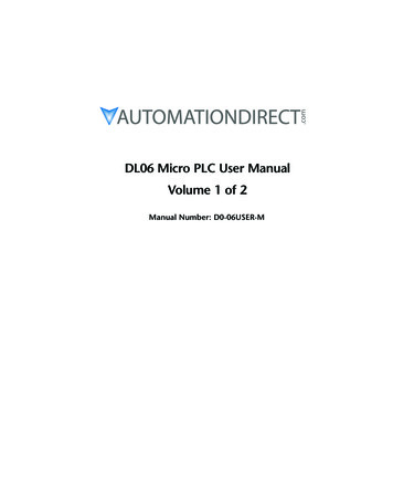
4. Default MIDI SettingsD#1BUTTON: A1ENCODER: CC 57RING: CC 79BUTTON: G#1ENCODER: CC 56F#1E1POT:BUTTON: C2ENCODER: CC 60RING: CC82G1POT:F1CC 51CC 52CENTER NOTE:CENTER NOTE:D#2BUTTON: A#1ENCODER: CC 58RING: TERTOUCH:AFTERTOUCH:D#3E3CC 71BUTTON: B1ENCODER: CC 59RING: CC81CC 72F#3CC 73CC 74BUTTON: D2ENCODER: CC 62RING: CC OUCH:AFTERTOUCH:G3A0F3G#3CC 75A3CC 76A#3CC 77CC D-1D#-1E-1F-1F#-1G-1G#-1A-1A#-1B-1C0POT:CC 53F2C1C#1POT:CENTER NOTE:BUTTON: C#2ENCODER: CC 61RING: CC 83CC 54C#0D0D#0F0E0F#0G0G#0B0CENTER NOTE:F#2D1CC 55TWEAKER DEFAULT MIDI MAP(Blank maps are available online in pdf format)23
5. The Settings Channel5 The Settings ChannelThe settings channel is reserved for the use of standard MIDI CC messages to configure differentTWEAKER settings. Send a CC number on this channel to the TWEAKER and, if it matches the CCnumber mapping for an LED ring or an encoder, the value will change its properties.The following properties can be modified using the settings channel:8 Encoder speed8 Encoder mode (absolute/relative)8 LED rings display style8 Local Control (CC# 122)The tables below describe each bit in the 7-bit value of the MIDI CC message for the Encoders, LEDRings, and Local Control. It is these combinations of bits that determine the final value of the CCmessage.EncodersPosition M0ES3ES2ES1ES0Value01111100LED RingsPosition RM3RM2RM1RM0Value01111100Local ControlLocal ControlPosition TENCAENCRANAxValue0000000024
5. The Settings Channel4RM Ring Mode4SB Security Bit (0 ignore message, 1 accept message)4ES Encoder Speed4EOM0 Encoder Output Mode (0 absolute,1 relative4EOM1 reserved 4ENCR Encoder Relative Local Control4ENCA Encoder Absolute Local Control4ANA Analog Local Control5.1 Encoder Settings5.1.1 Default SettingsSettings Channel:16Encoder Mappings:Min: CC56Max: CC625.1.2 Encoder Response TableValueReceived byTweakerExpected Change to Encoder PropertiesRing ModeEncoderOutput ModeEncoder Speed(global)0-63 nc nc nc 64FillRelative nc 65WalkRelative nc 66EQRelative nc 67SpreadRelative nc 68FillAbsolute nc 69WalkAbsolute nc 70EQAbsolute nc 71SpreadAbsolute nc 72FillRelative125
5. The Settings bsolute4103SpreadAbsolute426
5. The Settings Absolute7126EQAbsolute7127SpreadAbsolute7Sample MessagesCC 56, Channel 16, Velocity 64Puts the large navigation encoder in Relative ModeCC 56, Channel 16, Velocity 63No change to the large navigation encoder27
5. The Settings ChannelCC 57, Channel 16, Velocity 68Puts the top-left encoder in Absolute ModePuts the top-left encoder’s LED ring in Fill ModeNo change to encoder speedCC 57, Channel 16, Velocity 69Puts the top-left encoder in Absolute ModePuts the top-left encoder’s LED ring in Walk ModeNo change to encoder speedCC 57, Channel 16, Velocity 70Puts the top-left encoder in Absolute ModePuts the top-left encoder’s LED ring in EQ ModeNo change to encoder speedCC 57, Channel 16, Velocity 71Puts the top-left encoder in Absolute ModePuts the top-left encoder’s LED ring in Spread ModeNo change to encoder speed5.2 LED Ring Settings5.2.1 Default SettingsDefault Settings Channel:16Default LED Ring Mappings:Min: CC79Max: CC8428
5. The Settings Channel5.2.2 LED Rings Response TableValue Receivedby TweakerExpected Change to Encoder PropertiesRing ModeEncoderOutput ModeEncoder Speed(global)Encoder LocalControl of LEDRings0-63 nc n
and the Ableton Live Remote Script 8 An overlay for the included Traktor 2 LE software 8 An overlay for the included Ableton Live Remote Script 1.3 Product Registration Why not take a few minutes to register your new product? Registration enables us to keep a record of your produ