Transcription
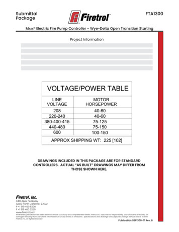
SubmittalPackageFTA1300MarkIII Electric Fire Pump Controller - Wye-Delta Open Transition StartingProject InformationDRAWINGS INCLUDED IN THIS PACKAGE ARE FOR STANDARDCONTROLLERS. ACTUAL “AS BUILT” DRAWINGS MAY DIFFER FROMTHOSE SHOWN HERE.3412 Apex PeakwayApex, North Carolina 27502P 1 919 460 5200F 1 919 460 5250www.firetrol.comWhile every precaution has been taken to ensure accuracy and completeness herein, Firetrol, Inc. assumes no responsibility, and disclaims all liability, fordamages resulting from use of this information or for any errors or omissions. Specifications and drawings are subject to change without notice. 2020Firetrol, Inc., All Rights Reserved.Publication SBP1300-71 Rev. B
Firetrol MarkIII Electric Fire Pump ControllerFTA1300 - Wye-Delta Open Transition StartingSpecifications1.0 Main Fire Pump ControllerThe main fire pump controller shall be a factory assembled, wired and tested unit.The controller shall be of the combined manual and automatic type designed for fullvoltage starting of the fire pump motor having the horsepower, voltage, phase andfrequency rating shown on the plans and drawings.1.1 Standards, Listings & ApprovalsThe controller shall conform to all the requirements of the latest editions of:NFPA 20, Standard for the Installation of Stationary Pumps for Fire ProtectionNFPA 70, National Electrical Code.The controller shall be listed by:Underwriters Laboratories, Inc., in accordance with UL218, Standard for Fire Pump Controllers Canadian Standards Association CSA-C22.2, Standard for Industrial ControlEquipment (cUL)CE - Low Voltage DirectiveThe controller shall be approved by:Factory Mutual (IEC 62091)The City of New York for fire pump service1.2 EnclosureThe controller components shall be housed in a NEMA Type 2 (IEC IP22) drip-proof, wallmounted enclosure with bottom entry gland plate and lifting lugs.1.3 Withstand Ratings (Short Circuit Current Ratings)All controller components shall be front mounted, wired and front accessible for maintenance. The available short circuit current ratings are shown below.200-208V 220-240V 380-415V 440-480 550-6005-150 HP 5-200 HP 5-350 HP 5-400 HP 5-500 HP100kAM - Standard100kA100kA100kAN/A150kAN - Intermediate150kA150kA150kAN/A200kAP - High200kA200kA200kAN/AN/AQ - IntermediateN/AN/AN/A100kAN/AR - 80Code200 HP250-400 HP 400-500 HP 450-500 HPM - Standard50A50kA50kA50kAN - IntermediateN/AN/AN/AN/AP - High100kA100kA100kA100kAQ - IntermediateN/AN/AN/AN/AR - StandardN/AN/AN/AN/ACode1.4 Power ComponentsThe controller shall include a combination isolating disconnect switch/circuit breaker,rated for not less than 115% of the motor full load current, mechanically interlocked andoperated with a single, externally mounted handle. The isolating disconnect switch/circuit breaker shall be mechanically interlocked so that the enclosure door cannot beopened with the handle in the ON position except by a hidden tool operated bypassmechanism. The isolating disconnect switch/circuit breaker shall be capable of beingpadlocked in the OFF position for installation and maintenance safety, and shall also becapable of being locked in the ON position without affecting the tripping characteristicsof the circuit breaker.
The controller will include a voltage surge arrestor and Wye-Delta Open Transitionmotor starter.The controller shall be equipped with a single handle, manually operated, emergencystart mechanism capable of being latched in the ON position.1.5 Operator Interface (HMI)The operator interface shall be a 7.0” LCD color touch screen (HMI technology) powered by an embedded microcomputer with software PLC logic. Included shall bekeypad type push-buttons for START, STOP and TEST.The screen shall include menus for: Home · Alarms · Configuration · History · Service ·Manuals · Language.The HMI shall graphically display the following: Voltage and Amperage of all 3 phases simultaneously using true RMS Technology · Motor Stopped/Running · StartingCause · Actuation Mode · Controller Type · Shutdown Mode · Date & Time · PumpRoom Temp. · System PressureSystem pressure shall be capable of being displayed as: PSI, kPa, Bar, Feet of Head orMeters of Water.The HMI shall allow programming and display of: Cut In & Cut Out Pressure Settings ·Minimum Run Timer · Sequential Start Timer · Periodic Test TimerThe HMI allows the user to select the language of the system and download themanual or view the manual on screen.1.6 State and Alarm IndicationVisual indication shall be provided for the following:Power Available Motor Run Periodic Test Manual Start Deluge Valve Start RemoteAutomatic Start Remote Manual Start Emergency Start Pump On Demand/Automatic Start Pump Room Temperature LockoutThe digital display shall visually indicate the following alarms: Locked Rotor Current Fail To Start Under/Over Current Under/Over Voltage Phase Unbalance Check Test Solenoid Valve Weekly Test Cut-In Not Reached Transducer Fault Control Voltage Not Healthy Motor Trouble Pump Room Alarm Invalid Cut-In Phase Reversal Power Loss Phase Loss L1 / L2 / L3 Low Water Level Pump On Demand Low Ambient Temp. Service RequiredAudible and visible alarm shall be provided for: Fail To StartRemote Alarm contacts shall be provided for:Power Available Phase Reversal Motor Run Common Pump Room Alarm (Overvoltage, Undervoltage, Phase Unbalance, Low/High Pump Room Temperature) CommonMotor Trouble (Overcurrent, Fail To Start, Undercurrent, Ground Fault)1.7 Pressure and Event RecordingThe system shall be capable of logging pressure data and operational events withtime/date stamp. The system shall display operational events for the lifetime of thecontroller and display the pressure data in text or graphical form. The controller shalllog the Date/Time of the first start-up and the controller total power on time fromthat date. The controller shall log first and last statistics for: First Setup · On Time ·Start Count · Last Start Time · Min/Max/Average System Pressure · Min/Max/AveragePump Room Temp. · Jockey Pump On Time/Start Count/Last Start Time · Phase toPhase Voltages with Date Stamp · Amps Per Phase with Date Stamp
1.8 USB Host ControllerA USB port capable of accepting a USB Flash Memory Disk shall be provided fordownloading pressure and event logs.1.9 Serial CommunicationsThe controller shall feature Modbus with TCP/IP frame format and shielded female RJ45connector2.0 Pressure Sensing / Wet PartsThe controller shall be supplied with a solid state pressure transducer with a range of0-500 psi calibrated for 0-300 psi (0-20.7 bar) and a run test solenoid valve. The wetparts shall be externally mounted and include a protective cover. The pressure sensing line connection to the transducer shall be 1/2-inch FNPT. Provisions for a redundant pressure transducer shall be provided.2.1 Seismic CertificationThe controller shall be certified to meet or exceed the requirements of the 2015 International Building Code, the 2016 California Building Code and OSHPD Special SeismicCertification Preapproval - OSP. The controller test criteria shall be per ICC-ES AC156and the Seismic Parameters per ASCE 7-10 Chapter 13.2.2 Controller OperationThe controller shall be capable of automatic starting via pressure drop, remote startsignal from an automatic device or a deluge valve. The controller can be manuallystarted via the START push-button, the RUN TEST push-button, or a remote signal froma manual device. Stopping can be achieved manually with the STOP push-button orautomatically after expiration of minimum run timer or test timer. The minimum runtimer (off delay), sequential start timer (on delay) and periodic test timer shall be fieldadjustable and include a visual countdown on the display.2.3 ManufacturerThe controller shall be a Firetrol brand.3412 Apex PeakwayApex, North Carolina 27502P 1 919 460 5200F 1 919 460 5250www.firetrol.comWhile every precaution has been taken to ensure accuracy and completeness herein, Firetrol, Inc. assumes no responsibility, and disclaims all liability, for damages resulting from use of this information or for any errors or omissions. Specifications and drawings are subject to change without notice. 2019 Firetrol, Inc., All Rights Reserved.Publication SP1300-60
Product DescriptionFTA1300MarkIII Electric Fire Pump Controllers - Wye-Delta Open Transition StartingDescription—Firetrol FTA1300 Wye-Delta, OpenTransition Starting Fire Pump Controllers are usedwith delta-wound squirrel cage motors. FTA1300controllers are of the open circuit transitiontype in which the motor circuit is opened duringthe transition from start to run. The controllermonitors, displays and records fire pump systeminformation.Actuating the controller by the pressure switch,START push-button or deluge valve contactcloses the start contactor connecting the motor to the line in the wye connection. The motorwill draw approximately 33% of its normal inrushcurrent and develop approximately 33% of itsnormal starting torque. After a time delay, themotor is automatically reconnected in delta, applying full voltage to the motor windings. Thesecontrollers are recommended especially for usewith generator sets.Approvals – Firetrol fire pump controllers arelisted by Underwriters’ Laboratories, Inc., in accordance with UL218, Standard for Fire PumpControllers, CSA, Standard for Industrial ControlEquipment, and approved by Factory Mutual.They are built to meet or exceed the requirements of the approving authorities as well asNEMA and the latest editions of NFPA 20, Installation of Centrifugal Fire Pumps, and NFPA 70,National Electrical Code.Standard Features — The following are includedas standard with each controller: Voltage surge protector Main Disconnect Switch sized for connectedmotor horsepower and voltage Fire pump Circuit Breaker Single Handle Isolating Disconnect Switch/Circuit Breaker mechanism Motor contactor Single Handle Emergency Manual Run Mechanism to mechanically close motor contactorcontacts in an emergency condition Built-in Start and Stop push-buttons to bypassautomatic start circuits Daylight Savings Time Option Elapsed Time Meter 7.0” LCD color touch screen (HMI technology)software upgradeable operator interfacepowered by an embedded microcomputerwith software PLC logic. 500 PSI Pressure Transducer (calibrated for300 PSI (20.7 Bar))and Test Solenoid for freshwater applications, externally mounted withprotective cover Audible Alarm Bell Pump Room Ambient Temperature Switch,Display and Alarms Pressure and Event Recording with Date Stampto System Memory Accessible VIA The User Interface and Downloadable to a USB Flash Drive Modbus Communications with TCP/IP frameformat and a shielded female RJ45 connector NEMA Type 2 (IEC IP22) enclosure with bottomentry gland plate and lifting lugs Suitable for use as Service Equipment The controller supplies visual indication ofthe following: Power Available Motor Run Periodic Test Manual Start Deluge ValveStart Remote Automatic Start RemoteManual Start Emergency Start Pump OnDemand (Automatic Start) Pump RoomTemp. Lockout The controller displays visual indication for thefollowing alarm conditions: Control VoltageNot Healthy Invalid Cut-In Lock Rotor Current Loss of Power Low Ambient Temp. LowWater Level Motor Trouble Phase Reversal Overcurrent Overvoltage Phase Loss L1 / L2 /L3 Phase Unbalanced Pressure TransducerFault Detected Pump On Demand PumpRoom Alarm Service Required Undercurrent Undervoltage Check Test Solenoid WeeklyTest Cut-In Reached Audible and Visible Indication for Fail To Start. DPDT 8A, 250VAC remote alarm contacts areprovided for: Power Available Phase Reversal Motor Run Common Pump Room Alarm (Overvoltage /Undervoltage / Phase Unbalance / Low PumpRoom Temp. / High Pump Room Temp) Common Motor Trouble (Overcurrent / FailTo Start / Undercurrent / Ground Fault) Field Adustable Timers with Visual Countdownfor Minimum Run (Off Delay), Sequential Start(On Delay) and Weekly Test Seismic Certification per IBC 2015, CBC 2016(Consult Factory for Verification)
Product Description - Options & ModificationsSPECIAL ENCLOSURES-EEnclosure, NEMA Type 4 (IP66), Painted Steel-FEnclosure, NEMA Type 4X (IP66), #304 Stainless Steel,Brushed Finish-FDEnclosure, NEMA Type 4X (IP66), #316 Stainless Steel,Brushed Finish-FDB Enclosure, NEMA Type 4X (IP66), #316 Stainless Steel,12 Gauge, Seam-Welded, Brushed Finish-FDP Enclosure, NEMA Type 4X (IP66), #316 Stainless Steel,Painted Finish-FXP Enclosure, NEMA Type 4X (IP66), #304 Stainless Steel,Painted Finish-GEnclosure, NEMA Type 12 (IP54), Painted Steel-TEnclosure, NEMA Type 3R (IP24), Painted Steel-UEnclosure, NEMA Type 3 (IP54), Painted SteelCIRCUIT BREAKER OPTION-NIntermediate withstand rating - 150,000 Amps RMSSym. (200-480V) - 100,000 Amps RMS Sym. (550-600V)-PHigh withstand rating200,000 Amps RMS Sym (200-480V)Note: Intermediate and High withstand ratings may not beavailable for all horsepowers and voltages. Consultfactory for availability.ANTI-CONDENSATION SPACE HEATERS-JSpace Heater, 120V Externally Powered with CircuitBreaker and Thermostat-KSpace Heater, 120V Externally Powered with CircuitBreaker and Humidistat-MSpace Heater, 240V Externally Powered with CircuitBreaker and Thermostat-NSpace Heater, 240V Externally Powered with CircuitBreaker and Humidistat-JKP Space Heater, 120V Externally Powered with CircuitBreaker and Thermostat and Humidistat in Parallel-MNP Space Heater, 240V Externally Powered with CircuitBreaker and Thermostat and Humidistat in Parallel-BY1 Alarm Output Contacts, Overcurrent-CTS1 Configurable Low Suction Pressure, Visible/OutputContacts with Suction Pressure Transducer-EH1 Alarm, Visible/Output Contacts, Main Relief ValveOpen-EKAlarm Visible/Output Contacts, Flow Meter Open-JRVisible Indicator, Jockey Pump Operating-JTAlarm, Audi
MarkIII Electric Fire Pump Controller - Wye-Delta Open Transition Starting Submittal FTA1300 Package Publication SBP1300-71 Rev. B 3412 Apex Peakway Apex, North Carolina 27502 P 1 919 460 5200 F 1 919 460 5250 www.firetrol.com While every precaution has been taken to ensure accuracy and completeness herein, Firetrol, Inc. assumes no responsibility, and disclaims all liability, for