Transcription
Copyright 2011 by International Business Machines Corp.CH A P T E R3A Design Technique:Data IntegrationModelingThis chapter focuses on a new design technique for the analysis and design of data integrationprocesses. This technique uses a graphical process modeling view of data integration similar tothe graphical view an entity-relationship diagram provides for data models.The Business Case for a New Design ProcessThere is a hypothesis to the issue of massive duplication of data integration processes, which is asfollows:If you do not see a process, you will replicate that process.One of the main reasons why there is massive replication of data integration processes inmany organizations is the fact that there is no visual method of “seeing” what data integrationprocesses currently exist and what is needed. This is similar to the problem that once plagued thedata modeling discipline.In the early 1980s, many organizations had massive duplication of customer and transactional data. These organizations could not see the “full picture” of their data environment and themassive duplication. Once organizations began to document and leverage entity-relationship diagrams (visual representations of a data model), they were able to see the massive duplication andthe degree of reuse of existing tables increased as unnecessary duplication decreased.The development of data integration processes is similar to those in database development.In developing a database, a blueprint, or model of the business requirements, is necessary toensure that there is a clear understanding between parties of what is needed. In the case of dataintegration, the data integration designer and the data integration developer need that blueprint orproject artifact to ensure that the business requirements in terms of sources, transformations, and45
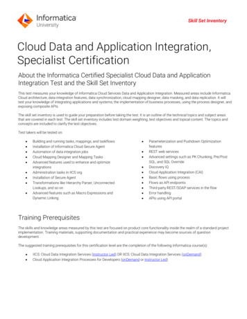
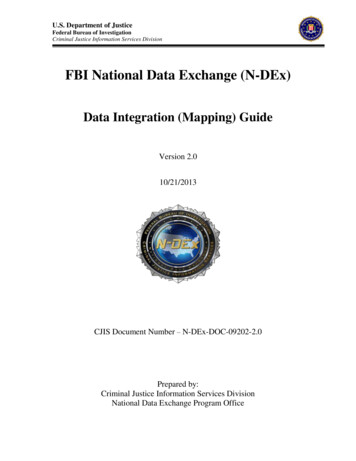
Copyright 2011 by International Business Machines Corp.46Chapter 3A Design Technique: Data Integration Modelingtargets that are needed to move data have been clearly communicated via a common, consistentapproach. The use of a process model specifically designed for data integration will accomplishthat requirement.Figure 3.1 depicts the types of data models needed in a project and how they are similar tothose that could be developed for data integration.Model TypeDataIntegrationConceptual Data ModelConceptual Data IntegrationModelLogicalModelsLogical Data ModelLogical Data IntegrationModelPhysicalModelsPhysical Data ModelPhysical Data IntegrationDatabaseData Stage logyErwinMoreDevelopmentTechnologyFigure 3.1Modeling paradigm: data and data integrationIIS Data Stage
Copyright 2011 by International Business Machines Corp.Improving the Development Process47The usual approach for analyzing, designing, and building ETL or data integrationprocesses on most projects involves a data analyst documenting the requirements for source-totarget mapping in Microsoft Excel spreadsheets. These spreadsheets are given to an ETL developer for the design and development of maps, graphs, and/or source code.Documenting integration requirements from source systems and targets manually into atool like Excel and then mapping them again into an ETL or data integration package has beenproven to be time-consuming and prone to error. For example: Lost time—It takes a considerable amount of time to copy source metadata from sourcesystems into an Excel spreadsheet. The same source information must then be rekeyedinto an ETL tool. This source and target metadata captured in Excel is largely nonreusable unless a highly manual review and maintenance process is instituted. Nonvalue add analysis—Capturing source-to-target mappings with transformationrequirements contains valuable navigational metadata that can be used for data lineageanalysis. Capturing this information in an Excel spreadsheet does not provide a cleanautomated method of capturing this valuable information. Mapping errors—Despite our best efforts, manual data entry often results in incorrectentries, for example, incorrectly documenting an INT data type as a VARCHAR in anExcel spreadsheet will require a data integration designer time to analyze and correct. Lack of standardization: inconsistent levels of detail—The data analysts who perform the source-to-target mappings have a tendency to capture source/transform/targetrequirements at different levels of completeness depending on the skill and experienceof the analyst. When there are inconsistencies in the level of detail in the requirementsand design of the data integration processes, there can be misinterpretations by thedevelopment staff in the source-to-target mapping documents (usually Excel), whichoften results in coding errors and lost time. Lack of standardization: inconsistent file formats—Most environments have multiple extracts in different file formats. The focus and direction must be toward the concept of read once, write many, with consistency in extract, data quality, transformation,and load formats. The lack of a standardized set of extracts is both a lack of techniqueand often a result of a lack of visualization of what is in the environment.To improve the design and development efficiencies of data integration processes, in termsof time, consistency, quality, and reusability, a graphical process modeling design technique fordata integration with the same rigor that is used in developing data models is needed.Improving the Development ProcessProcess modeling is a tried and proven approach that works well with Information Technologyapplications such as data integration. By applying a process modeling technique to data integration, both the visualization and standardization issues will be addressed. First, let’s review thetypes of process modeling.
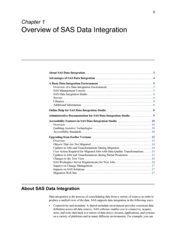
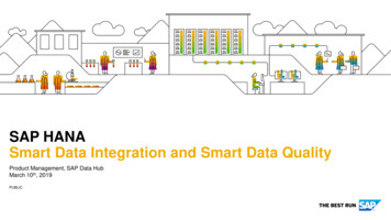
Copyright 2011 by International Business Machines Corp.48Chapter 3A Design Technique: Data Integration ModelingLeveraging Process Modeling for Data IntegrationProcess modeling is a means of representing the interrelated processes of a system at any level ofdetail, using specific types of diagrams that show the flow of data through a series of processes.Process modeling techniques are used to represent specific processes graphically for clearerunderstanding, communication, and refinement between the stakeholders that design and developsystem processes.Process modeling unlike data modeling has several different types of process models basedon the different types of process interactions. These different model types include processdependency diagrams, structure hierarchy charts, and data flow diagrams. Data flow diagramming, which is one of the best known of these process model types, is further refined into severaldifferent types of data flow diagrams, such as context diagrams, Level 0 and Level 1 diagramsand “leaf-level” diagrams that represent different levels and types of process and data flow.By leveraging the concepts of different levels and types of process modeling, we havedeveloped a processing modeling approach for data integration processes, which is as follows:Data integration modeling is a process modeling technique that is focused on engineeringdata integration processes into a common data integration architecture.Overview of Data Integration ModelingData integration modeling is a technique that takes into account the types of models needed basedon the types of architectural requirements for data integration and the types of models neededbased on the Systems Development Life Cycle (SDLC).Modeling to the Data Integration ArchitectureThe types of process models or data integration models are dependent on the types of processingneeded in the data integration reference architecture. By using the reference architecture as aframework, we are able to create specific process model types for the discrete data integrationprocesses and landing zones, as demonstrated in Figure 3.2.
Copyright 2011 by International Business Machines Corp.Overview of Data Integration ModelingExtract/PublishInitial StagingData Quality49Clean StagingTransformationLoadInvolved PartyLogical LoadModelRetail LogicalExtract ModelTech DQChecksCommercialLogical ExtractModelLoad-ReadyPublishBus ataEventLogical LoadModelBad Transactions0101 3443434 Missing FieldsDemand DepositLogical ExtractModelFigure 3.20304 535355 Referential Integrity0101 3443434 Missing Fields0304 535355 Referential IntegrityDesigning models to the architectureTogether, these discrete data integration layers become process model types that form acomplete data integration process. The objective is to develop a technique that will lead thedesigner to model data integration processes based on a common set of process types.Data Integration Models within the SDLCData integration models follow the same level of requirement and design abstraction refinementthat occurs within data models during the SDLC. Just as there are conceptual, logical, and physical data models, there are conceptual, logical, and physical data integration requirements that needto be captured at different points in the SDLC, which could be represented in a process model.The following are brief descriptions of each of the model types. A more thorough definitionalong with roles, steps, and model examples is reviewed later in the chapter. Conceptual data integration model definition—Produces an implementation-freerepresentation of the data integration requirements for the proposed system that willserve as a basis for determining how they are to be satisfied. Logical data integration model definition—Produces a detailed representation of thedata integration requirements at the data set (entity/table)level, which details the transformation rules and target logical data sets (entity/tables). These models are still considered to be technology-independent.The focus at the logical level is on the capture of actual source tables and proposed target stores. Physical data integration model definition—Produces a detailed representation ofthe data integration specifications at the component level. They should be representedin terms of the component-based approach and be able to represent how the data willoptimally flow through the data integration environment in the selected developmenttechnology.
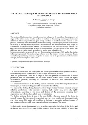
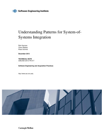
Copyright 2011 by International Business Machines Corp.50Chapter 3A Design Technique: Data Integration ModelingStructuring Models on the Reference ArchitectureStructuring data models to a Systems Development Life Cycle is a relatively easy process. Thereis usually only one logical model for a conceptual data model and there is only one physical datamodel for a logical data model. Even though entities may be decomposed or normalized within amodel, there is rarely a need to break a data model into separate models.Process models have traditionally been decomposed further down into separate discretefunctions. For example, in Figure 3.3, the data flow diagram’s top process is the context diagram,which is further decomposed into separate functional models.ContextDiagramProcess 1Figure 3.3Process 2Process 3A traditional process model: data flow diagramData integration models are decomposed into functional models as well, based on the dataintegration reference architecture and the phase of the Systems Development Life Cycle.Figure 3.4 portrays how conceptual, logical, and physical data integration models are broken down.Conceptual DataIntegration ModelingConceptualData Integration ModelHigh-Level LogicalData Integration ModelLogical DataIntegration ModelingLogicalExtraction ModelLogicalData Quality ModelLogicalTransform ModelLogicalLoad ModelPhysical DataIntegration tSystemExtractionSourceModelsModelsExtractFigure 3.4PhysicalCommon ComponentsModel(s)Data integration models by the Systems Development Life lsModels
Copyright 2011 by International Business Machines Corp.Logical Data Integration Models51Conceptual Data Integration ModelsA conceptual data integration model is an implementation-free representation of the data integration requirements for the proposed system that will serve as a basis for “scoping” how they are tobe satisfied and for project planning purposes in terms of source systems analysis, tasks and duration, and resources.At this stage, it is only necessary to identify the major conceptual processes to fully understand the users’ requirements for data integration and plan the next phase.Figure 3.5 provides an example of a conceptual data integration model.Model Name: CIA Data Integration ModelProject: Customer Interaction AnalysisLife Cycle Type: ConceptualDI Architecture Layer: N/ARetail LoanApplicationCommercial LoanApplicationLoan andTransaction DataQuality TransformConformingBankData WarehouseDemand DepositApplicationFigure 3.5Conceptual data integration model exampleLogical Data Integration ModelsA logical data integration model produces a set of detailed representations of the data integration requirements that captures the first-cut source mappings, business rules, and target data sets(table/file). These models portray the logical extract, data quality, transform, and load requirements for the intended data integration application. These models are still considered to be technology-independent. The following sections discuss the various logical data integration models.
Copyright 2011 by International Business Machines Corp.52Chapter 3A Design Technique: Data Integration ModelingHigh-Level Logical Data Integration ModelA high-level logical data integration model defines the scope and the boundaries for the projectand the system, usually derived and augmented from the conceptual data integration model. Ahigh-level data integration diagram provides the same guidelines as a context diagram does for adata flow diagram.The high-level logical data integration model in Figure 3.6 provides the structure for whatwill be needed for the data integration system, as well as provides the outline for the logical models, such as extract, data quality, transform, and load components.Model Name: CIA Data Integration ModelProject: Customer Interaction AnalysisLife Cycle Type: Logical, High-LevelDI Architecture Layer: N/ARetail LoanApplicationInvolved PartyLogical LoadModelRetail LogicalExtract ModelTech DQChecksBus formDepositDataErrorHandlingCommercialLogical ExtractModelBank DataWarehouseEventLogical LoadModelBad Transactions0101 3443434 Missing Fields0304 535355 Referential Integrity0101 3443434 Missing Fields0304 535355 Referential IntegrityDemandDepositApplicationDemand DepositLogical ExtractModelFigure 3.6Logical high-level data integration model exampleLogical Extraction Data Integration ModelsThe logical extraction data integration model determines what subject areas will need to beextracted from sources, such as what applications, databases, flat files, and unstructured sources.Source file formats should be mapped to the attribute/column/field level. Once extracted,source data files should be loaded by default to the initial staging area.Figure 3.7 depicts a logical extraction model.
Copyright 2011 by International Business Machines Corp.Logical Data Integration Models53Model Name: Commercial Loan Data Integration ModelProject: Customer Interaction AnalysisLife Cycle Type: LogicalDI Architecture Layer: ExtractCommercialLoanApplicationExtract Loanand CustomerFiles from theVSAM FileFigure 3.7Verify theExtract withthe Control FileFormat intoSubject AreaFilesLogical extraction data integration model exampleExtract data integration models consist of two discrete sub processes or components: Getting the data out of the source system—Whether the data is actually extractedfrom the source system or captured from a message queue or flat file, the network connectivity to the source must be determined, the number of tables\files must be reviewed,and the files to extract and in what order to extract them in must be determined. Formatting the data to a subject area file—As discussed in Chapter 2, “An Architecture for Data Integration,” subject area files provide a layer of encapsulation from thesource to the final target area. The second major component of an extract data integration model is to rationalize the data from the source format to a common subject area fileformat, for example mapping a set of Siebel Customer Relationship Management Software tables to a customer subject area file.Logical Data Quality Data Integration ModelsThe logical data quality data integration model contains the business and technical data qualitycheckpoints for the intended data integration process, as demonstrated in Figure 3.8.Regardless of the technical or business data quality requirements, each data quality dataintegration model should contain the ability to produce a clean file, reject file, and reject reportthat would be instantiated in a selected data integration technology.Also the error handling for the entire data integration process should be designed as areusable component.
Copyright 2011 by International Business Machines Corp.54Chapter 3A Design Technique: Data Integration ModelingModel Name: CIA Data Integration ModelProject: Customer Interaction AnalysisLife Cycle Type: LogicalDI Architecture Layer: Data QualityErrorHandlingRetail DataCommercialDataTechnical DQ ChecksBusiness DQ Checks1. Check Retail Data2. Check Commercial Data3. Check Demand Deposit Data1. Check Retail Data2. Check Commercial Data3. Check Demand Deposit DataFormat Clean FileDemand DepositDataFormat Reject FileBad Transactions0101 3443434 Missing FieldsFormat Reject ReportFigure 3.80304 535355 Referential Integrity0101 3443434 Missing Fields0304 535355 Referential IntegrityLogical data quality data integration model exampleAs discussed in the data quality architectural process in Chapter 2, a clear data qualityprocess will produce a clean file, reject file, and reject report. Based on an organization’s datagovernance procedures, the reject file can be leveraged for manual or automatic reprocessing.Logical Transform Data Integration ModelsThe logical transform data integration model identifies at a logical level what transformations (interms of calculations, splits, processing, and enrichment) are needed to be performed on theextracted data to meet the business intelligence requirements in terms of aggregation, calculation,and structure, which is demonstrated in Figure 3.9.Transform types as defined in the transformation processes are determined on the businessrequirements for conforming, calculating, and aggregating data into enterprise information, asdiscussed in the transformation architectural process in Chapter 2.
Copyright 2011 by International Business Machines Corp.Logical Data Integration Models55Model Name: CIA Data Integration ModelProject: Customer Interaction AnalysisLife Cycle Type: LogicalDI Architecture Layer: TransformationConform Loan Data1. Conform Retail Loan to theTarget Loan Subject Area2. Conform Commercial Loanto the Target Loan SubjectAreaConform Demand Deposit Data1. Conform Demand Deposit to the TargetAccount Subject Area2. Calculate Account TotalsFigure 3.9Logical transformation data integration model exampleLogical Load Data Integration ModelsLogical load data integration models determine at a logical level what is needed to load the transformed and cleansed data into the target data repositories by subject area, which is portrayed inFigure 3.10.Model Name: Involved Party Data Integration ModelProject: Customer Interaction AnalysisLife Cycle Type: LogicalDI Architecture Layer: LoadPerform Change DataCapture1. Update Customer Table2. Update Address TableLoad Customer TableLoad Address TableFigure 3.10Logical load data integration model exampleDesigning load processes by target and the subject areas within the defined target databasesallows sub-processes to be defined, which further encapsulates changes in the target from sourcedata, preventing significant maintenance. An example is when changes to the physical databaseschema occur, only the subject area load job needs to change, with little impact to the extract andtransform processes.
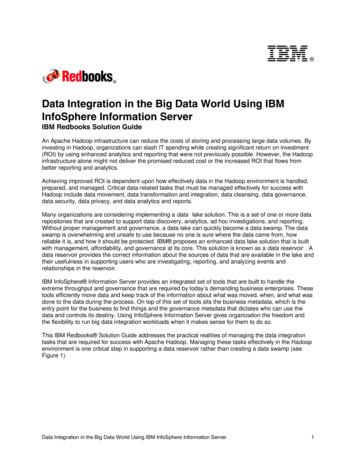
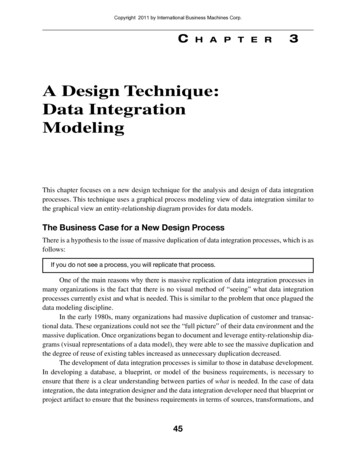
Copyright 2011 by International Business Machines Corp.56Chapter 3A Design Technique: Data Integration ModelingPhysical Data Integration ModelsThe purpose of a physical data integration model is to produce a detailed representation of the dataintegration specifications at the component level within the targeted data integration technology.A major concept in physical data integration modeling is determining how to best take thelogical design and apply design techniques that will optimize performance.Converting Logical Data Integration Models to Physical DataIntegration ModelsAs in data modeling where there is a transition from logical to physical data models, the sametransition occurs in data integration modeling. Logical data integration modeling determineswhat extracts, data quality, transformations, and loads. Physical data integration leverages a target-based design technique, which provides guidelines on how to design the “hows” in the physical data integration models to ensure that the various components will perform optimally in a dataintegration environment.Target-Based Data Integration Design Technique OverviewThe target-based data integration design technique is an approach that creates physical data integration components based on the subject area loads and the source systems that populate thosesubject areas. It groups logical functionality into reusable components based on the data movement patterns of local versus enterprise usage within each data integration model type.For example, in most data integration processes, there are source system-level and enterprise-level data quality checks. The target-based technique places that functionality either closeto the process that will use it (in this case, the extract process) or groups enterprise capabilities incommon component models.For example, for source system-specific data quality checks, the target-based techniquesimply moves that logic to the extract processes while local transformations are moved to loadprocesses and while grouping enterprise-level data quality and transformations are grouped at thecommon component level. This is displayed in Figure 3.11.
Copyright 2011 by International Business Machines Corp.Physical Data Integration ModelsLogicalExtractionData Integration ModelLogicalData IntegrationModeling57LogicalData QualityData Integration ModelLogicalLoadData Integration ModelModel Name: CIA Data Integration ModelProject: Customer Interaction AnalysisLife Cycle Type: LogicalDI Architecture Layer: TransformationModel Name:CIA Data Integration ModelProject: Customer Interaction AnalysisLogicalLife Cycle Type:Data QualityDI Architecture Layer:Model Name: Commercial Loan Data Integration ModelProject: Customer Interaction AnalysisLife Cycle Type:LogicalDI Architecture Layer:ExtractLogicalTransformsData Integration ModelModel Name: Involved Party Data Integration ModelProject: Customer Interaction AnalysisLife Cycle Type: LogicalDI Architecture Layer: LoadErrorHandlingRetail DataCommercialLoanApplicationTechnical DQDQ ChecksChecksTechnicalComm ercialDataExtract Loanand Customerfiles from theVSAM file1.Check Retail Data2. Check Com m ercial Data3. Check Dem and Deposit DataConform Loan DataBusiness DQ Checks2.2. ConformConform CommercialCommercial LoanLoantoto thethe TargetTarget LoanLoan SubjectSubjectAreaAreaFormat Clean FileVerify theextract with theControl FileDem and DepositDataFormat intoSubject AreafilesPerformPerform ChangeChange DataDataCapture1.1. ConformConform RetailRetail LoanLoan toto thetheTargetTarget LoanLoan SubjectSubject AreaArea1.Check Retail Data2. Check Com m ercial Data3. Check Dem and Deposit DataConformConform DemandDemand DepositDeposit DataData1.1. ConformConform DemandDemand DepositDeposit toto thethe TargetTargetAccountAccount SubjectSubject AreaArea1.1. Update Customer Table2.2. UpdateUpdate AddressAddress TableTable2.2. CalculateCalculate AccountAccount TotalsTotalsLoadLoad CustomerCustomer TableTableLoadLoad AddressAddress TableTableFormat Reject FileBad Transactions0101 3443434 Msi sni dl si g FeFormat Reject Report0304 535355 Referential Integrity0101 3443434 Missing Fields0304 535355 Referential IntegrityPhysicalData IntegrationModelingPhysicalSource SystemData Integration ModelFunctionalityFigure 3.11ExtractionInitial StagingSource Data QualityBusiness Data QualityTechnical Data QualityPhysicalCommon ComponentsData Integration ModelPhysicalSubject AreaComponent ModelPhysicalTargetComponent ModelCommon Data QualitySubject Area TransformationsBusiness Data QualityCalculationsTechnical Data QualitySplitsEnrichmentCommon TransformationsTarget FilteringCalculationsSubject Area TargetingSplitsEnrichmentsTarget FilteringTable-Base TargetingLoadDistributing logical functionality between the “whats” and “hows”The target-based data integration design technique is not a new concept: Coupling andcohesion, modularity, objects, and components are all techniques used to group “stuff” intounderstandable and highly functional units of work. The target-based technique is simply amethod of modularizing core functionality within the data integration models.Physical Source System Data Integration ModelsA source system extract data integration model extracts the data from a source system, performssource system data quality checks, and then conforms that data into the specific subject area fileformats, as shown in Figure 3.12.The major difference in a logical extract model from a physical source system data integration model is a focus on the final design considerations needed to extract data from the specifiedsource system.Designing an Extract Verification ProcessThe data from the source system files is extracted and verified with a control file. A control file isa data quality check that verifies the number of rows of data and a control total (such as loanamounts that are totaled for verification for a specific source extract as an example).It is here where data quality rules that are source system-specific are applied. The rationalefor applying source system-specific data quality rules at the particular source system rather thanin one overall data quality job is to facilitate maintenance and performance. One giant data quality job becomes a maintenance nightmare. It also requires an unnecessary amount of systemmemory to load all data quality processes and variables that will slow the time for overall jobprocessing.
Copyright 2011 by International Business Machines Corp.58Chapter 3A Design Technique: Data Integration ModelingCross-system dependencies should be processed in this model. For example, associativerelationships for connecting agreements together should be processed here.Model Name: Commercial Loan Data Integration ModelProject: Customer Interaction AnalysisLife Cycle Type: PhysicalDI Architecture Layer: Source System ExtractCommercialLoanApplicationExtract Loanand CustomerFiles from theVSAM FileErrorHandlingVerify theExtract withthe Control FileSource DQ ChecksCheck Commercial DataFormat intoSubject AreaFilesFormat Clean FileFormat Reject FileFormat Reject ReportFigure 3.12Bad Transactions0101 3443434 Missing Fields0304 535355 Referential Integrity0101 3443434 Missing Fields0304 535355 Referential IntegrityPhysical source system extract data integration model examplePhysical Common Component Data Integration ModelsThe physical common component data integration model contains the enterprise-level businessdata quality rules and common transformations that will be leveraged by multiple data integrationapplications. This layer of the architecture is a critical focal point for reusability in the overalldata integration process flow, with particular emphasis on leveraging existing transformationcomponents. Any new components must meet the criteria for reusability.Finally, in designing common component data integration models, the process flow isexamined on where parallelism can be built in to the design based on expected data volumes andwithin the constraints of the current data integration technology.Common Component Data Quality Data Integration ModelsCommon component data quality data integration models are generally very “thin” (less functionality) process models, with enterprise-level data quality rules. Generally, source system-specific data quality rules are technical in nature, whereas business data quality rules tend to beapplied at the enterprise level.
Copyright 2011 by International Business Machines Corp.Physical Data Integration Models59For example, gender or postal codes are considered business rules that can be applied asdata quality rules against all data being processed. Figure 3.13 illustrates an example of a common data quality data integration model.Note that the source-specific data quality rules have been moved to the physical source system extract data integration model and a thinner data quality process is at the common component level. Less data ensures that the data flow is not unnecessarily constrained and overallprocessing performance will be improved.Model Name: CIA Data Integration ModelProject:Life Cycle Type: PhysicalDI Architecture Layer: Common Component: Data QualityErrorHandlingRetail DataCommon DQ ChecksCommercialData1. Check Postal Code Ranges2. Check State Code RangesFormat Clean FileDemand DepositDataFormat Reject FileBad Transactions0101 3443434 Missing FieldsFormat Reject ReportFigure 3.130304 535355 Referential Integrity0101 3443434 Missing Fields0304 535355 Referential IntegrityCommon components—data quality data integration model exampleCommon Component Transformation Data Integration ModelsMost common transforms are those that conform data to an enterprise data model. Transformations needed for sp
data integration with the same rigor that is used in developing data models is needed. Improving the Development Process Process modeling is a tried and proven approach that works well with Information Technology applications such as data integration. By applying a process modeling technique to data integra-File Size: 635KB