Transcription
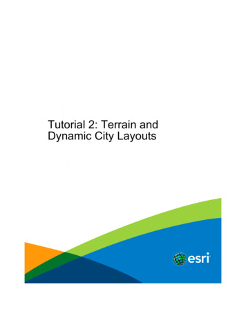
Realtime Procedural Terrain GenerationRealtime Synthesis of Eroded Fractal Terrain for Use in Computer GamesJacob Olsen, xenorg@imada.sdu.dkDepartment of Mathematics And Computer Science (IMADA)University of Southern DenmarkOctober 31, 2004AbstractDefinitionsThe main goal of this paper is to provide anoverview of a variety of methods for synthesisof eroded terrain for use in computer games, VRworlds and the like. Traditionally, such softwareuses either predefined terrains or runtime generated data based on simple fractal noise techniques.In recent years, the advances in processing powerof average home computers have made it possible to simulate erosion processes near-realtimeby putting emphasis on speed at the expense ofphysical correctness. This paper presents a fastmethod to synthesize natural looking fractal terrain and then proceeds to evaluate and suggestoptimizations for two of the most commonly usederosion algorithms [1, 2]. With some criteria forapplicability in computer games in mind, a newand much faster algorithm is then proposed. Finally, a few issues regarding terrain modificationsfor maximum playability are discussed.Data representationIn the algorithms described in this paper, terrainwill be represented by two-dimensional heightmaps using floating point values between 0 and 1.Unless otherwise stated, all examples use squaremaps with side length N 29 512, giving atotal of N 2 218 262144 cells, each cell containing a height value.The height map is denoted H and the individualcells are addressed as hi ,j , where i and j are coordinates ranging from 0 to 511. Some calculationswill address cells outside this range; in this case,modulo is used to wrap the coordinates around sothat the right neighbour of a right-most cell willbe the left-most cell in the same row etc.All implementations were done i Java, and all calculation times are from tests executed on a fairlystandard 2.4 GHz Pentium 4 PC.Defining erosionThe effects of erosion are difficult to describemathematically: The term erosion covers manynaturally occurring phenomena, and different terrain types and climates will produce many different kinds of changes to a landscape. For simplicity, a set of desirable traits (from a computergame development perspective) that will be usedto measure how eroded a height map is, is defined.Overall, most types of erosion dissolve materialfrom steep slopes, transport it downhill and thendeposit the material at lower inclinations. Thistends to make steep slopes even steeper, and flatten out low-altitude terrain when the transportedmaterial is deposited. To aid in the analysis of thechanges in inclination, the slope map S is definedFigure 1: A rendered view of a synthesized,eroded terrain created with the techniques discussed in this paper.1
such thatof the frequency, i.e.si,j max( hi,j hi,j hi,j hi,j hi 1,j , hi 1,j , hi,j 1 , hi,j 1 )P (f ) 1fawhere P (f ) is the power function of the frequencyand a is close to 1. This kind of noise approximates real-world uneroded mountainous terrainwell and has been used widely in computer graphics for the past decades. Two methods for generating 1/f -like noise, spectral synthesis and midpoint displacement, are discussed below.In generating a terrain base for the erosion algorithms to work on, it is worth noting that thecloser the terrain base is to the desired result,the less work is required by the (often calculationheavy) erosion algorithm itself. To help create aterrain base with better characteristics of erodedterrain, the use of Voronoi diagrams and perturbation filtering are introduced below.in other words, the greatest of the height differences between the cell and its four neighbours ina Von Neumann neighbourhood.This paper focuses on the synthesis of eroded terrain for use in computer games; therefore, theideal for eroded terrain must suit this application. Physical correctness and visual appearanceare secondary, what matters is applicability. Inmost computer games and VR environments using large-scale outdoor terrain, persons or vehiclesmove around on the terrain, and various structures are placed on the terrain. Movement andstructure placing is often restricted to low inclinations, which means that a low average valueof a height map’s corresponding slope map is desirable. This rule alone would make a perfectlyflat height map ideal, which is why a second ruleis added saying the greater the standard deviation of the slope map, the better. The ideal foreroded terrain is therefore a height map whosecorresponding slope map has a low mean value(reflecting the overall flattening of the terrain dueto material deposition) and a high standard deviation (material is dissolved from steep areas making them even steeper, and deposition flattens theflat areas further). The slope map mean value, s̄,and standard deviation, σs , are defined on theslope map S as follows:Spectral synthesisSpectral synthesis simulates 1/f noise by addingseveral octaves (layers) together, each octave consisting of noise with all its spectral energy concentrated on a single frequency. For each octave, thenoise frequency is doubled and the amplitude Ais calculated byA piwhere i is the octave number starting with 0 atthe lowest frequency and p is called the persistence. Letting p 0.5 will approximate 1/f noisebecause each time the frequency is doubled in thenext octave, the amplitude will be halved.The octaves themselves are created by fillingin evenly spaced pseudo random numbers corresponding to the octaves’s frequency, and then calculate the remaining values by interpolation - seeFigure 2 for a visual comparison of interpolationmethods. While cubic interpolation gives the bestresults, the slightly visible vertical and horizontalartifacts caused by linear interpolation are an acceptable trade-off for a computation time reducedto roughly one fifth.N 1 N 11 X Xs̄ 2si,jN i 0 j 0vu 1 N 1Xu 1 NXtσs (si,j s̄)2N 2 i 0 j 0Using these, an overall ”erosion score”, ε, is defined asσsε s̄Midpoint displacementAnother approach at simulating 1/f noise is bya midpoint displacement method, in this case thediamond-square algorithm [3, 4, 5]. Instead ofcalculating every cell in several octaves (up to 9octaves with N 29 ) and then adding togetherthe octaves, the value of each cell need only becalculated once.The midpoint displacement method works by recursively calculating the missing values halfway(on the assumption that s̄ 6 0)Generation of base terrainA technique often used for fast terrain generation is simulating 1/f noise (also known as ”pinknoise”) which is characterized by the spectral energy density being proportional to the reciprocal2
eroded look by multiplying the size of the offsetrange with the height average when calculatingnew values. This causes low altitude areas to become smoother, thereby simulating deposition oferoded material. This method is referred to assmoothed midpoint displacement.Figure 2: Cubic interpolation (left) versus linear interpolation (right) for the spectral synthesisalgorithm.between already known values and then randomlyoffset the new values inside a range determinedby the current depth of the recursion. Witha persistence of 0.5, this range is halved witheach recursive step, and an approximation of1/f noise is created. Ideally, the random offsetsshould have a gaussian distribution inside the offset range, but for the purpose of synthesizing terrain, uniformly distributed values are acceptable(and much faster to calculate).The implementation done for this paper is thesquare-diamond algorithm, named after the order in which midpoint values are determined (seeFigure 3).ss csss cabc csc cscc csc css c c c cs s sc c c c ccdscsscscscscscscscsFigure 4: Gaussian (left) versus uniform (right)distribution of random offsets for the midpointdisplacement algorithm.Voronoi diagramsThe problem with using 1/f noise for simulatingreal world terrain is that it is statistically homogeneous and isotropic - properties that real terraindoes not share. One way to break the monotonyand control the major characteristics of the landscape are Voronoi diagrams whose use in procedural texture generation has been described bySteven Worley [6]. Voronoi diagrams can be usedfor a variety of effects when creating proceduraltextures - most variants resemble some sort ofcell-like structures that can be used to simulatetissue, sponge, scales, pebbles, flagstones, or inthis case, entire mountains.The implementation used in this paper works bydividing the map into regions and then randomlyplace a number of ”feature points” in each region. For each cell in the map, a set of valuesdn , n 1, 2, 3, . . . are calculated according to adefined distance metric so that d1 is the distanceto the nearest feature point, d2 is the distance tothe next nearest distance point etc. Linear combinations of the formcscsceFigure 3: Two iterations of the diamond-squarealgorithm. Pseudo random number are used forinitial values in step a. In step b (the ”diamond”step) a new value is found by offsetting the average of the four values of step a. Step c (the”square” step) fills in the rest of the midpointvalues also by offsetting the average of the fourneighbours of each new point. Steps d and e showthe next iteration.Figure 4 shows a visual comparison of the twoways of distributing values inside the random offset ranges. Although uniform distribution produces a more jagged terrain, this can be compensated for by lowering the persistence. Since theversion using gaussian distribution takes 4 timeslonger to generate, uniform distribution is to bepreferred.The midpoint displacement method also allowsfor individual adjustments of the random offset ranges depending on coordinates or altitude,which can be used to give the terrain a moreh c1 d1 c2 d2 c3 d3 · · · cn dnwith coefficients c1 . . . cn will then producethe cellular structures - see Figure 5 for examples.For creating mountainous features,the coefficients c1 1 and c2 1 (withthe rest being zeroes) are used as it can adddistinct ridge lines and connected riverbeds tothe terrain. These values also give the Voronoidiagrams another useful property which will be3
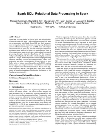
Combination and perturbationAlthough Voronoi diagrams have some usefulproperties that 1/f noise lacks, they are no substitute for the noise functions. The best resultsare achieved with some combination of both; inthis case two thirds smoothed diamond-squaremethod noise and one third Voronoi diagram withcoefficients c1 1 and c2 1 will be used. Thiscombination is referred to as the combined heightmap.To crumple the straight lines of the Voronoi diagram, a perturbation filter as described in [6]pages 90-91 is applied. This filter works by using a noise function (similar to the ones describedabove) to calculate a displacement with randomdistance and direction for each cell. The combined height map before and after perturbationcan be seen in Figure 7. The magnitude of theperturbation filtering is set to 0.25, meaning thata given point in the height map cannot be displaced more than N4 cells.The perturbation filtering itself also increases theerosion score because some areas are stretchedand some are compressed, which increases σs .Figure 8 shows the average relationship betweenperturbation magnitude and erosion score for atlarge number of test runs on the combined heightmap generated from different random seed numbers. Erosion score rises to a maximum at a perturbation magnitude of 0.25 and then slowly declines.Figure 5: Examples of Voronoi diagrams withcoefficients c1 1 (upper left), c2 1 (upperright), c3 1 (bottom left), c1 1 and c2 1(bottom right).covered in the section regarding playability issues.Normally, distances are determined by the Euclidean distance metricpd dx2 dy 2which is quite slow because of the square root.Changing the distance metric tod dx2 dy 2produces a large speedup. As Figure 6 shows, thedifference in the resulting height map is insignificant. This optimization together with a reduction in search radius when finding nearest featurepoints (which occasionally produces minor errors)reduces calculation time to one third.Figure 7: The combined height map before perturbation (left) and after (right).The final base terrain is shown in Figure 9. Forvisual comparison, all image examples of variouserosion algorithms in the following sections usethis terrain as a starting point. Figure 10 showsa rendered view of this height map.AnalysisFigure 6: Euclidean distance metric (left) versus the faster distance metric (right) for Voronoidiagrams.Average calculation times and erosion scores forthe methods discussed in this section can be seenin Table 1. As can be seen, the implementationsof spectral synthesis and midpoint displacement4
Erosion 0.4500.000.250.500.75Perturbation magnitude1.00Figure 8: The relationship between perturbationmagnitude and erosion score for the combinedheight map.Figure 9: The base terrain used in image examples of the erosion algorithms.all achieve nearly the same erosion score, but themidpoint displacement method with uniform random offset distribution is by far the fastest. Thesmoothed version is only marginally slower, butmanages to achieve a higher erosion score.The Voronoi diagrams in themselves do not scoreas much as the noise functions, but the faster metric seems to be better suited for the coefficientsused. When combined with the modified versionof the midpoint displacement method, the erosion score almost reaches the level of the modifiedmidpoint displacement method alone. As shownin Figure 8, the perturbation filter improves theerosion score even further.With N 512 the base terrain can be synthesizedin less than 1 second. Even with N 1024, thesynthesis of the base terrain is done in less than3 seconds.done by examining each cell and its neighbourhood in turn. Two different types of neighbourhoods are used: The Moore neighbourhood whichincludes all 8 neighbours of a cell, and the VonNeumann neighbourhood which only includes 4of the neighbouring cells (see Figure 11). Withthe currently examined cell having value h andits neighbours being named hi , the height difference to each neighbour, di , is defined asd i h himeaning that lower neighbours produce positiveheight differences. For maximum correctness, theMoore neighbourhood was used in both referenceimplementations.Erosion algorithmsThermal erosionTwo types of erosion algorithms are examined inthis section, namely thermal erosion (sometimesreferred to as thermal weathering) and hydraulicerosion. These were first described by Ken Musgrave et al in 1989 [1], and have since establishedthemselves as a base from which various improvements (mostly in terms of physical correctness)have been suggested [2, 7, 8, 9, 10].A reference implementation of each type is compared to speed optimized version that will stilldeliver comparable results. For thermal erosion,the original method suggested in [1] is used, whilea version of hydraulic erosion suggested in [2] isused because of its speed.Both methods are iterated cellular automatameaning that calculations in each iteration areOverviewThermal erosion simulates material braking looseand sliding down slopes to pile up at the bottom.The reference implementation works as follows: Apercentage of the material at the top of a slopewhose inclination is above a threshold value - thetalus angle T - will be moved down the slope untilthe inclination reaches T : di T : hi c(di T )hi d i T : hiThis is illustrated in Figure 12: At the firsttimestep, d1 T and d2 T , which means thatmaterial will be moved from h to h2 . With c 1,the amount of moved material results in d2 T5
TypeSpectral synthesis, cubic interpolationSpectral synthesis, linear interpolationMidpoint displacement, Gaussian distributionMidpoint displacement, uniform distributionMidpoint displacement, uniform distribution, smoothedVoronoi diagram, Euclidean metric, long search rangeVoronoi diagram, fast metric, short search rangeNoise and Voronoi combinationNoise and Voronoi combination, perturbedNoise and Voronoi combination, perturbedN5125125125125125125125125121024Calc. time0.783 s0.157 s0.439 s0.108 s0.144 s1.322 s0.468 s0.709 s0.831 s2.738 sErosion 0.673Table 1: Calculation times and erosion scores for the methods discussed in the first section. Calculationtimes for combinations include time to calculate the noise and Voronoi maps. All numbers are averagesfrom a large number of test runs.h1h2h3h4hh5h6h7h8h1h2hh3h4Figure 11: Moore (left) and Von Neumann(right) neighbourhoods for cellular automata.OptimizationsTo produce a speed optimized version of the reference implementation, four changes were made:Figure 10: A rendered view of the base terrainused in image examples of the erosion algorithms.For easy comparison, all rendered views use thesame camera position and direction.1. A Von Neumann neighbourhood was used instead of the Moore neighbourhood.2. Material distribution was changed so thatmaterial is only distributed to the lowestneighbour instead of all lower neighbours.and d1 T . However, this is a simplified example where material from h only needs to be movedto one neighbour cell. In the case where severalneighbours whose height difference is above thetalus angle exist, the moved material must be distributed after the formhi hi c(dmax T ) 3. Material distribution was changed to allowmore material to be moved per iteration.4. The calculations for each cell changes theheight map immediately instead of beingwritten to a difference map that is appliedafter an entire iteration is completed.didtotalThe reference implementation maintains valuesfor dmax and dtotal , which means that for everyneighbour hi of a cell h, the following must bedone:where dmax is the greatest of the di and dtotal isthe sum of the di greater than T .A reasonable value for c is 0.5; higher values maycause oscillation when the changes to the heightmap are applied only after completion of an entire iteration, and lower values will simply causeslopes steeper than T a slower asymptotical approach to the talus angle. For the talus threshold,a value of T N4 was chosen.d i h hiif (di talus) :dtotal dtotal diif (di dmax ) :dmax di6
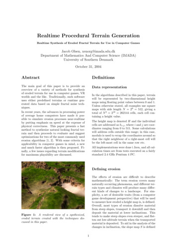
d1 Tthe height map remains unchanged until all cellshave been processed. One way to solve this is tochange the height map immediately when moving material - in the above example this wouldmean that the hole would not receive any morematerial once it was raised to a level where theheight differences to the surrounding cells werebelow the talus threshold. Another advantage ofdirect changes to the height map is a slight increase in calculation speed.When experimenting with different kinds ofneighbourhoods, it was also noted that a ”rotated” version of the Von Neumann neighbourhood (see Figure 13) gave slightly better resultsboth in terms of higher erosion score and less difference between the two versions.d2 Th1hh2t 0d1 Td2 Th1hh2t 1h1Figure 12: A simplified example of thermal erosion: d2 is greater than the talus angle, so material is moved from h to h2 until d2 equals thetalus angle.h2hh3Switching from the Moore neighbourhood to theVon Neumann neighbourhood will halve the number of times these conditional checks have to bedone. Since the amount of moved material percell is proportional to dmax , using the Von Neumann neighbourhood will move the same amountof material 50% of the time. Even if the dmax ofthe Moore neighbourhood is outside of the VonNeumann neighbourhood, the dmax of the VonNeumann neighbourhood still tends to be closeto its value.When the amount of material to be moved hasbeen calculated, each neighbour hi whose di Tdireceives a fraction proportional to dtotal(wheredtotal is the sum of the di greater than T ). Thiscan be simplified a lot by distributing materialto the lowest neighbour only as this renders thecalculation of dtotal and the fractions to be distributed superfluous. A drawback is that less material can be moved per cell, which can partly becompensated for by moving as much material has possible:dmax h 2h4Figure 13: The modified Von Neumann neighbourhood used in the speed optimized version ofthermal erosion.AnalysisCalculation time averages for the first 500 iterations of the two implementations can be seen inFigure 14. Time required per iteration remainsconstant for both implementations, but the reference implementation takes 6 times longer; 500iterations are calculated in 60 seconds, while thespeed optimized version does it in 10 seconds.Figure 15 shows erosion score averages of thefirst 500 iterations. The reference implementation scores 5% better after 500 iterations, butthe speed optimized version seems to be more effective during the first 80 iterations. To explorethis further, a new graph was created, showingthe height map difference after every 10 iterations(see Figure 16). The optimized version seems tostabilize faster, meaning that most of the changeis done during the first 50 iterations. The reference implementation does more change overallduring the 500 iterations, but does not seem tobe stabilizing until after 150 iterations.For practical or visual applications, no more than50 iterations of any of the versions are needed tochange the shape of the terrain to show the distinct effects of thermal erosion, namely the con-This causes h to be levelled with its lowest neighbour if their height difference is greater than T .In the reference implementation, only a percentage c of the maximum amount of material to bemoved was transfered. This was done to avoidoscillation, and the same problem applies here:Four large height values surrounding a deep holemay not only fill up the hole, but create a tallspike instead. Oscillations like this occur because7
Change per 10 500OptimizedFigure 16: Change per 10 iterations of the first500 iterations of the reference and optimized implementation of thermal erosion.Figure 14: Calculation times of the first 500 iterations of the reference and optimized implementation of thermal erosion.Erosion scoreHydraulic w0100200300IterationsReference400Hydraulic erosion simulates changes to the terrain caused by flowing water dissolving material,transporting it and depositing it elsewhere.For the reference implementation of hydraulicerosion, a slightly altered version of Beneš andForsbach’s method [2] has been used. The algorithm is split up into four independent steps:5001. Appearance of new water.2. Water eroding the underlying terrain andcapturing the dissolved material.Optimized3. Transportation of water and sediment.Figure 15: Erosion scores of the first 500 iterations of the reference and optimized implementation of thermal erosion.4. Evaporation of water and deposition of sediment.Apart from the height map, hydraulic erosion alsomaintains a water map W and a sediment map Mfor keeping track of the flow of water and dissolvedmaterial.In step 1, a constant amount of water Kr is addedto each cell every iteration to simulate rain:stant angled slopes. Figure 17 compares heightmaps produced by the two versions after 50 iterations, and Figure 18 shows rendered views ofthese height maps.The difference between the outputs of the two implementations after 50 iterations is 2% on average, where a difference of 100% corresponds to aheight map with all height values at 0 versus aheight map with all height values at 1.wi,j wi,j KrIn step 2, an amount of the height value proportional to the amount of water present in the samecell is converted to sediment:hi,j hi,j Ks wi,jmi,j mi,j Ks wi,jWhile thermal erosion manages to increase theerosion score by lowering the angle of most slopes,terrains produced by this kind of erosion does notresemble the ideal defined earlier since the constant angled slopes leave very little completely flatarea.where Ks is the solubility constant of the terrain.In step 3, the water and its contents of dissolvedmaterial are transported following a set of rules8
Figure 17: Comparison between the reference implementation of thermal erosion (left) and the speedoptimized version (right). Images show the height map after 50 iterations.similar to the material distribution in thermalerosion. Only now, water is being distributed tothe neighbour cells instead and the distributionseeks to level out any height differences of the total altitude a h w so thatcell. The amount of sediment mi to be transported to a neighbouring cell i is thereforea aiIn step 4, a percentage of the water w determined by the evaporation coefficient Ke evaporates again: mi m for each neighbour i in the cell’s neighbourhoodwhose total height is less than that of the currently examined cell.The amount of water moved to the ith neighbour, wi , is calculated by wi min(w, a) wiww w (1 Ke )The maximum amount of sediment mmax thatcan be carried by the water w is determined bythe sediment capacity coefficient Kc such thatdidtotalmmax Kc wwhere a a ā is the total height of the currentcell minus the average total height of the cellsinvolved in the distribution, di a ai and dtotalis the sum of all positive di .If the total amount of water to be moved awayfrom the currently examined cell is less than theamount of water present in this cell, an amountequalling the difference between the total heighta of the cell and the average total height ā after water distribution, is moved. If more waterneeds to be moved away than the cell holds, whatever amount of water present will be distributedamong the lower neighbours. These two cases areillustrated in Figure 19.Once the water distribution has been calculated,sediment distribution follows quite easily. An assumption is made that all dissolved material m isuniformly distributed within the water w of theOnce part of the water has evaporated, theamount of sediment exceeding the maximum capacity (if any), m, is transfered back to h: m max(0, m mmax )m m mh h mThe various constants and coefficients used in thereference implementation are:KrKsKeKc9 0.01 0.01 0.5 0.01
Figure 18: Renderings from the two height maps shown in Figure 17 - the left image shows the reference implementation after 50 iterations, and the right image shows the speed optimized version after 50iterations.aa3. Instead of maintaining a sediment map, allwater is assumed to contain an equal amountof dissolved material.a–a ww1h1whw1w2h2h1t 0whw2h24. The calculations for each cell change theheight and water maps immediately insteadof being written to difference maps that areapplied after an entire iteration is completed.t 1As with the speed optimizations of thermalerosion, the change in neighbourhood is done tohalve the number of neighbour cells for whichthe following needs to be done for every cell ineach iteration:awaa–a ww1w1h1ht 0h2h1hw2h2ai hi midi a aiif (di 0) :dtotal dtotal diatotal atotal aicells cells 1t 1Figure 19: Two cases for water distribution inhydraulic erosion. In the first case, only a fraction of the water w is moved to level out the totalheights, while in the second case all of the available water is distributed to the neighbours withoutreaching level.where atotal and cells are used to calculate ā. Thechange of neighbourhood stills results in roughlythe same amount of water being transported;only the distribution differs. This is because theamounts of water being transported are so smallcompared to the height differences between thecells that the second case in Figure 19 wherew a ā by far is the most frequently occurring.This allows for a good approximation of the waterdistribution by simply moving water to the lowest neighbour only, thereby saving the need forcalculating the fractions received by each lowerneighbour.In the reference implementation, the choice ofcoefficients such that Ks Kc means that theOptimizationsTo speed optimize the reference implementation,four changes were made:1. A Von Neumann neighbourhood was used instead of the Moore neighbourhood.2. Water distribution was changed so that wateris only distributed to the lowest neighbourinstead of all lower neighbours.10
amount of material dissolved per water equals thetransport capacity of the water. This causes allthe water to always be at maximum sediment saturation: Any water evaporation is immediatelyfollowed by sedimentation of the material that exceeds the transport capacity. Since m Kc wfor every cell, there is no need to maintain a separate sediment map. Even with Kc Ks this is agood approximation, since w drops exponentiallywhich means that maximum saturation is reachedvery quickly.To limit reads and writes to the height and water maps further, all changes are written directlyinstead of using difference maps that are appliedonly after the entire iteration has been completed.10,000 iterations, the optimized version reaches ascore of 7.8. However, at this point none of theheight maps resemble the original at all; the optimized implementation reaches its high score bychanging the entire height map to a few almostcompletely levelled terraces divided by very steepslopes.After 100 iterations, the optimized version scores20% better than the reference and has a muchhigher erosion score growth rate during the first25 iterations where the reference implementationproduces almost no increase in erosion score atall.Erosion scoreAnalysisCalculation time averages for the first 500 iterations of the two implementations can be seen inFigure 20. Time required per iteration remainsvery close to constant for both i
Realtime Synthesis of Eroded Fractal Terrain for Use in Computer Games Jacob Olsen, xenorg@imada.sdu.dk Department of Mathematics And Computer Science (IMADA) University of Southern Denmark October 31, 2004 Abstract The main goal of this paper is to provide an overview of a variety of methods for synthesis of eroded terrain for use in computer .