Transcription
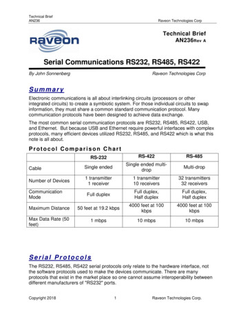
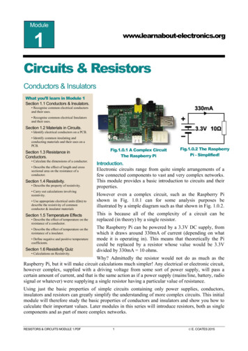
Module1www.learnabout-electronics.orgCircuits & ResistorsConductors & InsulatorsWhat you’ll learn in Module 1Section 1.1 Conductors & Insulators. Recognise common electrical conductorsand their uses. Recognise common electrical Insulatorsand their uses.Section 1.2 Materials in Circuits. Identify electrical conductors on a PCB. Identify common insulating andconducting materials and their uses on aPCB.Section 1.3 Resistance inConductors. Calculate the dimensions of a conductor. Describe the effect of length and crosssectional area on the resistance of aconductor.Section 1.4 Resistivity. Describe the property of resistivity. Carry out calculations involvingresistivity. Use appropriate electrical units (Ωm) todescribe the resistivity of commonconductor & insulator materialsSection 1.5 Temperature Effects Describe the effect of temperature on theresistance of a conductor. Describe the effect of temperature on theresistance of a insulator. Define negative and positive temperaturecoefficients.Section 1.6 Resistivity Quiz Calculations on Resistivity.Fig.1.0.1 A Complex CircuitThe Raspberry PiFig.1.0.2 The RaspberryPi - Simplified!Introduction.Electronic circuits range from quite simple arrangements of afew connected components to vast and very complex networks.This module provides a basic introduction to circuits and theirproperties.However even a complex circuit, such as the Raspberry Pishown in Fig. 1.0.1 can for some analysis purposes beillustrated by a simple diagram such as that shown in Fig. 1.0.2.This is because all of the complexity of a circuit can bereplaced (in theory) by a single resistor.The Raspberry Pi can be powered by a 3.3V DC supply, fromwhich it draws around 330mA of current (depending on whatmode it is operating in). This means that theoretically the Picould be replaced by a resistor whose value would be 3.3Vdivided by 330mA 10 ohms.Why? Admittedly the resistor would not do as much as theRaspberry Pi, but it will make circuit calculations much simpler! Any electrical or electronic circuit,however complex, supplied with a driving voltage from some sort of power supply, will pass acertain amount of current, and that is the same action as if a power supply (mains/line, battery, radiosignal or whatever) were supplying a single resistor having a particular value of resistance.Using just the basic properties of simple circuits containing only power supplies, conductors,insulators and resistors can greatly simplify the understanding of more complex circuits. This initialmodule will therefore study the basic properties of conductors and insulators and show you how tocalculate their important values. Later modules in this series will introduce resistors, both as singlecomponents and as part of more complex networks.RESISTORS & CIRCUITS MODULE 1.PDF1 E. COATES 2015
www.learnabout-electronics.orgResistors & Circuits Module 11.1 Conductors & InsulatorsWhat you’ll learn in Module 1.1After studying this section, you shouldbe able to: Recognise common electricalconductors and their uses. Recognise common electricalInsulators and their uses.ConductorsIn electrical and electronic circuits and components, CONDUCTORS are materials that allowelectric current to flow through them because their atomic structure allows the outermost (free)electrons to easily move from one atom to another, and because the electrons carry a negativeelectric charge they are easily repelled by an applied negative electric charge, and attracted by apositive charge. Therefore applying a voltage between the two ends of a conductor causes an‘electron drift’ from negative to positive giving rise to an electric current. Suitable materials to actas conductors include:Most MetalsSome GasesSolutions of Acids, Alkalis & Salts in waterMetal ConductorsMetals such as copper, aluminium, and some alloys (mixtures of two or moremetals), e.g. brass, phosphor-bronze and manganin are widely used inelectrical and electronic circuits. Electric connectors in switches or in a mains13A plug use a good conductor such as brass for their main contacts.Phosphor bronze, an alloy of copper and tin with some phosphorous, isspringy in nature and useful for contacts such as the fuse holder in a mainsplug, as well as "brushes" used to carry current between the stationary androtating parts in some electric motors.The best metal conductor of all is pure silver; however it has two drawbacks. Its surface readilytarnishes when exposed to air, this creates a high resistance surface that reduces its conductivity.Although this doesn't cause a great problem in high voltage conductors, it can significantly reduceconduction in low voltage applications such as switch or plug/socket contacts. Silver is alsoexpensive compared to other metals such as copper (the second best metal conductor). AlthoughCopper is the most popular metal for electrical conductors,it also tarnishes, so copper conductorsare often plated with less tarnishable metals such as nickel. For optimum contact conduction in lowvoltage applications however, gold plating is used because, although slightly less conductive thanpure copper, gold does not tarnish.Gold plating is commonly used to reduce 'skin effect' in conductors used for high frequency currentapplications. Skin effect is the tendency of high frequency currents to flow mainly close to thesurface of the conductor. Using gold plating therefore provides a current path with a resistance onlyslightly worse than copper in the body of the cable, but considerably better that the tarnished outerlayer of the cable or connector. Hence it is common to see gold plated sockets and connectors indevices such as mobile phones and even audio equipment.Manganin is another copper-based alloy but with higher resistance, used in the construction of wirewound resistors and heater elements for high power applications.RESISTORS AND CIRCUITS MODULE 1 PDF2 E. COATES 2015
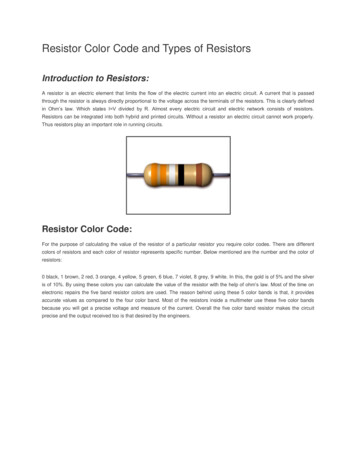
www.learnabout-electronics.orgResistors & Circuits Module 1Aluminium is commonly used as a conductor. Though not as good aconductor as copper, it is much lighter and useful for applications such asthe large power distribution cables crossing the landscape strung onelectricity pylons. Copper cables would be too heavy for this job.Aluminium also has some properties, useful in the construction oftransistors and diodes.Silver is an even better conductor than copper, but since it is moreexpensive, it is only used in very small amounts.The conductivity of metals used for electrical purposes may be comparedto an internationally agreed standard value, as shown in Fig 1.1.1. That ofannealed copper, that is copper that has been heated and cooled at acontrolled rate to soften the metal and remove any stresses present. Othercommonly used metals can therefore be compared to this standard where aFig. 1.1.1 Conductivity100% rating indicates the same conductivity as copper, over 100%of Metalsindicates a better conductor and less that 100%, a worse conductor. Notethat the table only compares standard samples of metals and does not take into consideration effectsdue to tarnishing or different frequencies of current etc.Conductive GasesSome gases can pass current, such as neon for example, whichproduces a typical orange glow when a small electric current is passedthough it at a high voltage. Neon indicator lamps have many uses andcan be used with either AC or DC current.In neon (fluorescent)lighting, colours other than orange can be produced by adding gasessuch as argon, mercury, or helium at low pressure. Light is producedby applying a high voltage between two electrodes at either end of thetube, which causes the gas molecules to ionise and so emit photons,giving light either directly through the clear glass tube, or indirectlyby exciting a phosphor coating on the wall of the tube to give agreater range of colours.Neon & Fluorescent Lightingon Hong Kong WaterfrontInsulatorsMaterials that prevent the flow of electric current are called INSULATORS. These are mostly solidmaterials in which the outer electrons of each atom are tightly bonded to the nucleus of the atom,preventing any electron movement within a ‘normal range’ of applied voltage. Materials commonlyused in electronic circuits include:Plastics (e.g Polystyrene, P.V.C. Bakelite and Polythene)Glass (including Fibre Glass)CeramicsResins (e.g. epoxy resins)Paper (usually impregnated with wax, resin etc.)Rubber (Natural or synthetic)Insulated Tool HandlesAirBoth the terms ‘Insulator’ and ‘Conductor’ are relative. That is, they each have some properties ofthe other as well as their own. For example an insulator may pass very small currents, but notsufficiently to be called a conductor. An insulator can work well at low voltages, such as thosefound in battery operated equipment, but fail totally and pass large currents if connected to a muchhigher voltage.RESISTORS AND CIRCUITS MODULE 1 PDF3 E. COATES 2015
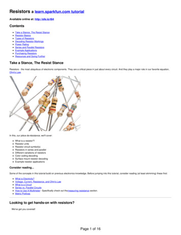
www.learnabout-electronics.orgResistors & Circuits Module 11.2 Materials in CircuitsWhat you’ll learn in Module 1.2After studying this section, you should beable to: Identify electrical conductors on aPCB. Identify common insulating andconducting materials and their uses on aPCB.Fig. 1.2.1 Micro-controller Circuit BoardConductors and Insulators in circuit boards.A good example of how various materials are used for conductors and insulators in electronics canbe seen on the printed circuit board shown in Fig. 1.2.1.1. The conducting strips are made from copper, which is a very good conductor.2. Electrical connections between the components and copper strips are made with solder (mainlytin), which is another good conductor, and has the advantages of being easy to melt, as well asmaking good electrical and mechanical contact.3. The board itself is made from a good insulator, usually paper impregnated with resin, which isknown as SRBP (synthetic resin bonded paper), or in high quality boards from glass-fibre board.Glass, paper and resin are all very good insulators.4. The contacts of the chip holder are gold plated. This gives an excellent low resistance contact andalso prevents tarnishing (oxidisation), which would otherwise increase the contact resistance overtime.5. The chip is encapsulated in black resin; this gives good electrical insulation and, being black,provides good heat conduction to disperse heat generated within the chip.RESISTORS AND CIRCUITS MODULE 1 PDF4 E. COATES 2015
www.learnabout-electronics.orgResistors & Circuits Module 11.3 Resistance in ConductorsWhat you’ll learn in Module 1.3After studying this section, you should beable to: Calculate the dimensions of a conductor. Describe the effect of length and crosssectional area on the resistance of aconductor.How the Dimensions of a Conductor Affect its ResistanceThe ability of any conductor in an electrical circuit to pass current is judged by its electricalRESISTANCE. Resistance is the ability to OPPOSE the flow of electric current. The greater thevalue of resistance of any conductor, the less current will flow. The resistance of a conductordepends mainly on three things:1. The LENGTH of the conductor.2. The CROSS SECTIONAL AREA of the conductor.3. The MATERIAL of which the conductor is made.Because the resistance is greater in longer conductorsthan in shorter ones, then:RESISTANCE (R) IS PROPORTIONAL TO LENGTH (L) and iswritten as R L ( means proportional to.)Therefore the longer the conductor, the more resistanceis present and so less current flows.Also, because resistance is less in conductors with alarge cross sectional area:Fig. 1.3.1 Calculating the Dimensionsof a ConductorRESISTANCE (R) IS INVERSELY PROPORTIONAL TO CROSS SECTIONAL AREA (A)Which is written as R 1/A (or R A-1).The greater the cross sectional area, the more current can flow along the conductor, so the lower thevalue of the conductor’s resistance.Circular ConductorsWhen the conductor has a circular cross section, the area of a circle can be found by using theformula:π r2 Where π 3.142 and r is the radius of the circle.If the cross section of the conductor is square or rectangular, the cross sectional area of theconductor can still be found by simply multiplying the width by the height. Most conductors, foundin cables etc. are of course circular in cross section.The Material from which the conductor is made also affects its resistance, by an amount dependingon the RESISTIVITY of the material, described in Resistors & Circuits Module 1.4.RESISTORS AND CIRCUITS MODULE 1 PDF5 E. COATES 2015
www.learnabout-electronics.orgResistors & Circuits Module 11.4 ResistivityWhat you’ll learn in Module 1.4After studying this section, you should beable to: Describe the property of resistivity. Carry out calculations involving resistivity. Use appropriate electrical units (Ωm) todescribe the resistivity of common conductor& insulator materialsHow Materials Affect ResistanceProvided that the dimensions (length and crosssectional area) of any conductor do not change, itsresistance will remain the same. If two conductors ofexactly the same dimensions have a different resistance,they must be made of different materials.One way to describe a material (any material) is by its RESISTIVITY. This is the amount ofresistance present in a piece of the material OF STANDARD DIMENSIONS. Every material can bedefined in this way. The resistivity of any material is defined as the resistance of a piece of thatmaterial having a length of one metre and a cross sectional area of one square metre (i.e. a cube ofmaterial one metre square); the resistivity of the material being the resistance across opposite facesof the standard cube.Resistivity is given the symbol ρ. This is not a letter p but a lower case Greek letter r (called rho)and is measured in a unit called the OHM METER, written ΩM. (Note: this is not the same asohms/metre or ohms per metre)So the resistance of any conductor can be found by relating the three factors;Length: L Cross Sectional Area: AResistivity: ρThe following formula can be used to find the resistance of any conductor, providing that itsdimensions and its resistivity are known.Remember that, as conductors are usually circular in section, the cross sectional area may need tobe found using the basic formula for the area of a circle. i.e. A π r2 or A π(d/2)2 where r and dare the given radius and given diameter, respectively, and π 3.142.Important.When using this (or any) formula you must convert any sub-unit (mm, cm etc.) into itsSTANDARD SI UNIT e.g Metres (M). Otherwise your result may be out by a factor of 100 or 1000or more.Resistivity problems can be tricky to work out since you have to remember several things atonce, using the cross sectional area formula AND the resistivity formula together, convertingto standard SI units, and using resistivity constants. Maybe you could use a little practice?Try a short Resistivity Quiz and if you need a little help with the maths, download our"Maths Tips" booklet to get you started.Approximate Resistivity of some common materials. (in Ωm)CONDUCTORSAluminium 2.7 x 10INSULATORS-8(P.T.F.E. polytetrafluoroethylene, used to insulatehigh voltage cables.)P.V.C. 5.4 x 10¹⁵Copper 1.7 x 10⁻⁸Glass 104Iron 10.5 x 10⁻⁸Quartz 1012Mercury 96 x 10-8P.T.F.E 1012RESISTORS AND CIRCUITS MODULE 1 PDFIt can be seen from this list that the resistivity ofinsulators is much higher than that of conductors.6 E. COATES 2015
www.learnabout-electronics.orgResistors & Circuits Module 11.5 Temperature Effects on ResistanceWhat you’ll learn in Module 1.5After studying this section, you should beable to: Describe the effect of temperature on theresistance of a conductor. Describe the effect of temperature on theresistance of an insulator. Define negative and positive temperaturecoefficients.How Temperature Changes ResistanceAlthough the resistance of a conductor changes with thesize of the conductor (e.g. thicker wires have lessresistance to current flow than thinner wires), theresistance of a conductor also changes with changingtemperature. This may be expected to happen because,as temperature changes, the dimensions of theconductor will change as it expands or contracts.However, materials that are classed as CONDUCTORS tend to INCREASE their resistance with anincrease in temperature. INSULATORS however are liable to DECREASE their resistance with anincrease in temperature. Materials used for practical insulators (glass, plastic etc.) only exhibit amarked drop in their resistance at very high temperatures. They remain good insulators over alltemperatures they are likely to encounter in use.These changes in resistance cannot therefore be explained by a change in dimensions due to thermalexpansion or contraction. In fact for a given size of conductor the change in resistance is due mainlyto a change in the resistivity of the material, and is caused by the changing activity of the atoms thatmake up the material.Temperature and Atomic StructureThe reasons for these changes in resistivity can be explained by considering the flow of currentthrough the material. The flow of current is actually the movement of electrons from one atom toanother under the influence of an electric field. Electrons are very small negatively chargedparticles and will be repelled by a negative electric charge and attracted by a positive electriccharge. Therefore if an electric potential is applied across a conductor (positive at one end, negativeat the other) electrons will "migrate" from atom to atom towards the positive terminal.Only some electrons are free to migrate however. Others within each atom are held so tightly totheir particular atom that even an electric field will not dislodge them. The current flowing in thematerial is therefore due to the movement of "free electrons" and the number of free electronswithin any material compared with those tightly bound to their atoms is what governs whether amaterial is a good conductor (many free electrons) or a good insulator (hardly any free electrons).The effect of heat on the atomic structure of a material is to make the atoms vibrate, and the higherthe temperature the more violently the atoms vibrate.In a conductor, which already has a large number of free electrons flowing through it, the vibrationof the atoms causes many collisions between the free electrons and the captive electrons. Eachcollision uses up some energy from the free electron and is the basic cause of resistance. The morethe atoms jostle around in the material, the more collisions are caused and hence the greater theresistance to current flow.In an insulator however, there is a slightly different situation. There are so few free electrons thathardly any current can flow. Almost all the electrons are tightly bound within their particular atom.Heating an insulating material vibrates the atoms, and if heated sufficiently, the atoms vibrateviolently enough to actually shake some of their captive electrons free, creating free electrons tobecome carriers of current. Therefore at high temperatures the resistance of an insulator can fall,and in some insulating materials, quite dramatically.RESISTORS AND CIRCUITS MODULE 1 PDF7 E. COATES 2015
www.learnabout-electronics.orgResistors & Circuits Module 1In a material where the resistance INCREASES with an increase in temperature, the material is saidto have a POSITIVE TEMPERATURE COEFFICIENT.When resistance FALLS with an increase in temperature, the material is said to have a NEGATIVETEMPERATURE COEFFICIENT.In general, conductors have a POSITIVE temperature coefficient, whilst (at high temperatures)insulators have a NEGATIVE temperature coefficient.Different materials within either group have different temperature coefficients. Materials chosen forthe construction of the resistors used in electronic circuits are carefully selected conductors thathave a very low positive temperature coefficient. In use, resistors made from such materials willhave only very slight increases in resistivity, and therefore their resistance. Using such materials forthe manufacture of resistors creates components whose value changes only slightly over a givenrange of temperature.Materials chosen as insulators will have a very low NEGATIVE TEMPERATURE COEFFICIENTover their working range of temperature.RESISTORS AND CIRCUITS MODULE 1 PDF8 E. COATES 2015
www.learnabout-electronics.orgResistors & Circuits Module 11.6 Resistivity QuizWhat you’ll learn in Module 1.6After studying this section, you should beable to: Descibe common materials used inelectronic circuits. Relate resistance to the dimensions andresistivity of a conductor. Calculate the cross sectional area ofconductors. Carry out calculations involving resistivity& resistance.Try a few calculations based on Resistivity. For theseyou just need to use the information in Module 1.4"Resistivity" and Module 1.3 "Resistance inConductors" pages, hopefully it'll be a breeze.Because you may be using more than one formula forany problem it is important to remember to use thecorrect formula at the right time.Before you start, these few tips may make the problemseasier if you follow them carefully.1. Work out the answers using pencil and paper; if you don't write out the problem you WILL getmixed up half way through and end up with the wrong answer.2. Of course the answer is not just a number, it will be a certain number of Ohms or metres, don'tforget to show the correct unit (e.g. Ω) or your answer is meaningless.3. Convert all sub units such as mm to metres when you put them into the appropriate formula. Ifyou slip up here you'll get really stupid answers, thousands of times too big or too small.To help you on the right track why not download our "Maths Tips" booklet, whichshows how to use your calculator with exponents and engineering notation to dealwith those sub-units and get the right answer every time.Not got a scientific calculator? The "Maths Tips" booklet explains what you need(and what you don't need so you don't spend your money unnecessarily). If you don'twant to buy a scientific calculator, you can always pick up a free one on the net. PCusers can try Calc98 from www.calculator.org/download.html. Whichever calculatoryou choose remember that you should read the instructions to become familiar withthe working methods you should use as these do vary from calculator to calculator.OK so now you have read these instructions, you are ready to start. Here is a way to set out a typicalproblem on paper so you (with practice) don't get confused.Firstly list all the values given in the problem, followed by the value that needs to be found for theanswer. For example if the problem asks for the resistance of a cable of given dimensions andmaterial, the following list can be made:ρ (of copper) 1.7 x 10⁻⁸ Ωm (17 E-9 or 17 EXP-9 when entering it into your calculator inStandard Form, depending on which model you use)L (Length of cable) 7md (Diameter of cable) 0.5mm (500 E-6 or 500 EXP-6 metres in Standard Form)A (Cross Sectional Area of cable in square metres) π(d/2)2 3.142 x ((500 EXP-6/2)2) 196.4 EXP-9m2Therefore R (ρL) / A (17 EXP-9 x 7) / 196.4 EXP-9 605mΩRESISTORS AND CIRCUITS MODULE 1 PDF9 E. COATES 2015
www.learnabout-electronics.orgResistors & Circuits Module 1Note that when the diameter (or the radius) of a cable is given it is necessary to firstly work out itscross sectional area in square metres (m2) before the formula relating R, to ρ, length and crosssectional area can be used. Look at the "Resistivity" page for more help in working out the crosssectional area.Note: If you are using Calc98 for your calculations you need to set the View Option Displaymenu to Engineering (under the "Decimal" choices) and it would be a good idea whilst you are inthis menu to select 2 from the Decimals drop down box, to set the number of digits after thedecimal place. This will round your answer down to two decimal places, which is sufficientlyaccurate for most uses and stops you getting silly answers such as 4.66666666667mm, which wouldbe far too accurate for any practical scale of measurement.Resistivity Calculations Practice(Calculate your answers with pencil, paper and calculator; you can check your answers on line at.http://www.learnabout-electronics.org Resistors Module 1)1.A wire 12m long has a resistance of 1.5 Ω. What will be the resistance of 16m of the same wire?a) 1.6Ωb) 2 Ωc) 12Ωd) 1.4Ω2.A sample of copper wire of 0.2mm radius has a length of 5m. If the resistivity of the copper is 1.7 x10⁻⁸, what would be the resistance of the wire?a) 60.49Ωb) 42.5Ωc) 4.25Ωd) 0.676Ω3.What is the resistance of 100m of copper wire, having a diameter of 1.024mm?a) 2.06Ωb) 5.15Ωc) .515Ωd) 3.7Ω4.The resistance of a 50m length of wire is found to be 0.83 ohms. Its diameter is 1.15mm. What is itsresistivity and from what metal is it most probably made?a) 2.7 x 10⁻⁸ aluminium b) 10.5 x 10⁻⁸ ironc) 17.2 x 10⁻⁹ aluminium d) 1.72 x 10⁻⁸ copper5.What is the length of a copper wire having a radius of 0.25mm if its resistance is found to be 0.2 Ω?a) 2mb) 2.31mc) 16.96mRESISTORS AND CIRCUITS MODULE 1 PDFd) 1.7m10 E. COATES 2015
Materials that prevent the flow of electric current are called INSULATORS. These are mostly solid materials in which the outer electrons of each atom are tightly bonded to the nucleus of the atom, preventing any electron movement within a ‘normal range’ of applied voltage. Materia