Transcription
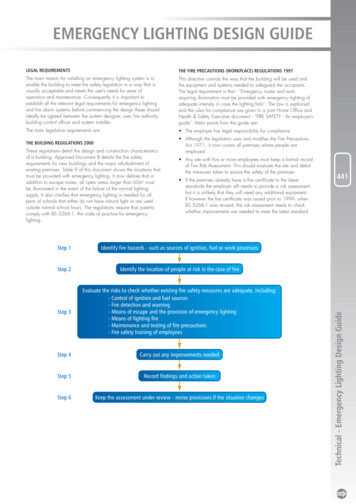
EMERGENCY LIGHTING DESIGN GUIDETHE FIRE PRECAUTIONS (WORKPLACE) REGULATIONS 1997The main reason for installing an emergency lighting system is toenable the building to meet fire safety legislation in a way that isvisually acceptable and meets the user’s needs for ease ofoperation and maintenance. Consequently it is important toestablish all the relevant legal requirements for emergency lightingand fire alarm systems before commencing the design these shouldideally be agreed between the system designer, user, fire authority,building control officer and system installer.This directive controls the way that the building will be used andthe equipment and systems needed to safeguard the occupants.The legal requirement is that - “Emergency routes and exitsrequiring illumination must be provided with emergency lighting ofadequate intensity in case the lighting fails”. The law is explainedand the rules for compliance are given in a joint Home Office andHealth & Safety Executive document - “FIRE SAFETY - An employer’sguide”. Main points from the guide are:The main legislative requirements are: The employer has legal responsibility for complianceTHE BUILDING REGULATIONS 2000 Although the legislation uses and modifies the Fire PrecautionsAct 1971, it now covers all premises where people areemployedThese regulations detail the design and construction characteristicsof a building. Approved Document B details the fire safetyrequirements for new buildings and the major refurbishment ofexisting premises. Table 9 of this document shows the locations thatmust be provided with emergency lighting. It now defines that inaddition to escape routes, all open areas larger than 60m2 mustbe illuminated in the event of the failure of the normal lightingsupply. It also clarifies that emergency lighting is needed for allparts of schools that either do not have natural light or are usedoutside normal school hours. The regulations require that systemscomply with BS 5266-1, the code of practice for emergencylighting. Any site with five or more employees must keep a formal recordof Fire Risk Assessment. This should evaluate the site and detailthe measures taken to ensure the safety of the premises If the premises already have a fire certificate to the lateststandards the employer still needs to provide a risk assessment,but it is unlikely that they will need any additional equipment.If however the fire certificate was issued prior to 1999, whenBS 5266-1 was revised, the risk assessment needs to checkwhether improvements are needed to meet the latest standardStep 1Identify fire hazards - such as sources of ignition, fuel or work processesStep 2Identify the location of people at risk in the case of fireStep 3Evaluate the risks to check whether existing fire safety measures are adequate, including:- Control of ignition and fuel sources- Fire detection and warning- Means of escape and the provision of emergency lighting- Means of fighting fire- Maintenance and testing of fire precautions- Fire safety training of employeesStep 4Carry out any improvements neededStep 5Record findings and action takenStep 6Keep the assessment under review - revise provisions if the situation changes441Technical - Emergency Lighting Design GuideLEGAL REQUIREMENTS
EMERGENCY LIGHTING DESIGN GUIDETHE FIRE PRECAUTIONS (WORKPLACE) REGULATIONS 1997 (cont’d)EMERGENCY LIGHTING - SYSTEM DESIGNFrom this directive there are a number of points that are of majorimportance to emergency lighting system design.This section provides guidance on system design to meet BS 5266Parts 1 and 7: 1999 and so achieve compliance with legislation The evaluation of areas with a fire risk assists when decidingwhich areas need protection, e.g. a school chemicallaboratory may be smaller than 60m2 but still need emergencylighting, as combustible materials and sources of ignition wouldbe present The assessment of the location of employees and any visitors tothe site assist in determining the most appropriate escape routes The guidance to the directive gives detailed requirements for thesuitability of escape routes and calls for the installation ofemergency lighting to be in accordance with BS 5266-1442 It recommends that advice on the installation should be givenby a competent person who specialises in emergency lightingsystems Continued maintenance and testing must be correctly carriedout, to comply with the directive The equipment used must be capable of being demonstratedas of adequate quality. Compliance with the appropriateBritish Standard, or other approved third party scheme,gives evidence of this. The standard for luminaires isBS EN 60598-2-22. ICEL 1001 registration endorses thespacing data of these luminaires. The standard for centralbattery systems is BS EN 50171Note: When the premises are being assessed for risk,shortcomings in other areas of fire protection can be compensatedfor by improved levels of emergency lighting and fire alarms.Compliance with BS5266-1:1999 is deemed to comply withthese requirements.Technical - Emergency Lighting Design GuideTHE HEALTH AND SAFETY (SAFETY SIGNS AND SIGNALS)REGULATIONS 1996This regulation requires the adequate provision of signs protectedby emergency lighting. It details that signs should be located at allfinal exits and also on the escape routes at any location where theroute may be in doubt.OTHER REQUIREMENTSIn addition to fire safety legislation, some workplaces require alicence from the Local Authority, including theatres and cinemas,sport stadiums and premises for public entertainment, music,dancing, gambling and the sale of alcohol. Other premises mustbe registered with the Local Authority and be inspected by the FireAuthority, including nursing homes, children's homes, residentialcare homes and independent schools. Both licensed and registeredpremises have to pass a fire inspection to confirm that they havesystems complying with BS 5266-1 for the emergency lighting andBS 5839 for fire equipment. Records of a system are now essentialto maintain the validity of approvals and licences.DESIGN OBJECTIVEBS 5266, when referring to the provision of Escape Lighting insection 4.2, requires that when the supply to all or part of thenormal lighting in occupied premises fails, escape lighting isrequired to fulfil the following function:(a) To indicate clearly and unambiguously the escape routes.(b) To provide illumination along such routes to allow safemovement towards and through the exits provided.(c) To ensure that fire alarm call points and fire fighting equipmentprovided along escape routes can be readily located.(d) To permit operations concerned with safety measures.BS 5266-1 recommends that discussions should be held priorto commencing the design, to establish the areas to be covered,the method of operation, the testing regime and the most suitabletype of system. These discussions should include the owner oroccupier of the premises, the system designer, the installer,the supplier of the equipment and the fire authority.Note: BS5266 will be revised during 2004 following thepublication of EN50172. For up to date information visit ourwebsite at www.cooper-ls.com. Alternatively visit the BritishStandards Institute website, at www.bsi-global.com
STAGE 1LOCATE LUMINAIRES AT MANDATORY “POINTS OF EMPHASIS”Initial design is conducted by situating luminaires to reveal specific hazards and highlight safety equipment and signs, in addition toproviding illumination to assist safe travel along the escape route. This should be performed regardless of whether it is an emergencyescape route or an open (anti-panic) area. Only when this is accomplished should the type of luminaire or its light output be considered.BS5266 Pt 7: 1999 requires that the luminaires sited at points of emphasis must comply with BS EN 60 598-2-22.Specific locations where a luminaire must be provided are:At each exit doorAll safety exit signsOutside and near each final exitNear stairs so that each tread receives directlightAt each change of directionNear each first aid postNear any other change of floor levelAt each intersection of corridorsNear each piece of fire fighting equipment andcall pointNote - the term near means within 2 metres measured horizontallyTechnical - Emergency Lighting Design Guide443
EMERGENCY LIGHTING DESIGN GUIDESTAGE 2ENSURE THAT EXIT SIGNS ARE OF CORRECT FORMAT AND SIZESection 4.1 of BS5266 Pt 7 states that “Signs which are provided at all exits intended to be used in an emergency and along escape routesshall be illuminated to indicate unambiguously the route of escape to a point of safety”. Where direct sight of an emergency exit is notpossible, an illuminated directional sign (or series of signs) shall be provided to assist progression towards the emergency exit. Sign formats should not be mixed- BS2560: 1975Old-style signs now obsolete. Should have been replaced byDecember 1998- BS 5499 Pt 1Signs are still acceptable, if they are already in the building- European Signs Directive FormatThis came into force on 1st April 1996, under The SignsDirective444EXITEXITIf there is any doubt as to the most appropriate format of sign,guidance should be obtained from the local Fire Authority. Maximum viewing distancesFor all format of safety signs the maximum viewing distances and luminance conditions are given in BS 5266 pt7/EN 1838 Signs can beeither internally illuminated, such as exit boxes or edge lit emergency luminaires with a screened sign that have a controlled illuminance,or painted signs with an external emergency light illuminating them. Maximum viewing distances are:Internally illuminated signs - 200 x the panel heightTechnical - Emergency Lighting Design GuidehExternally illuminated signs - 100 x the panel heighth 200 x h 100 x h Illumination requirementsThe sign must conform to the colours of ISO 3864, which defines that exit and first aid signs must be white with green as the contrastcolour. The ratio of luminance of the white colour to the green colour must be between 5:1 and 15:1. The minimum luminance of any10mm patch area on the sign must be greater than 2cd/m2 and the ratio of maximum to minimum luminance shall be less than 10:1 foreither colourmin luminance 2cd/m2ratio of luminance shall beless than 10:1 for either colourcontrast of the colours must bebetween 5:1 and 15:1Note: Internally illuminated exit signs are pre-tested to ensure they meet these requirements, provided that they comply with EN 60598-2-22.If the sign is designed to be externally illuminated, considerable care must be taken by the system designer to see that these conditions are met.Even though an emergency luminaire must be sited within 2 metres from the sign (see stage 1) calculations should still be made to check thatthe sign is adequately illuminated.
STAGE 3LOCATE LUMINAIRES AT THE FOLLOWING ESSENTIAL AREAS IN THE BUILDINGSLocate luminaires at the following essential areas in the buildings.These locations are not part of the escape route but because of their risk they require protection by emergency lighting.a) Lift cars - although only in exceptionalcircumstances will they be part of theescape route, do present a problemin that the public may be trapped inthem in the event of a supply failure.c) Escalators - to enable users to get offthem safely.e) Covered car parks - the normalpedestrian routes should be providedwith non-maintained luminaires of atleast 1 hour duration.445d) Motor generator, control or plantrooms - require battery suppliedemergency lighting to assist anymaintenance or operating personnelin the event of failure.Technical - Emergency Lighting Design Guideb) Toilets - all toilets for the disabled andfacilities exceeding 8m2 floor area orwithout borrowed lights.
EMERGENCY LIGHTING DESIGN GUIDESTAGE 4ESCAPE ROUTE LIGHTINGWhen the points of emphasis have been covered, it is essential to provide any additional luminaires to ensure that minimum illuminance levelsare met to enable the routes to be used safely. In addition, every compartment on the escape route must have at least two luminaires,to provide some light in the event of luminaire failure. Light Level RequirementsBS 5266 Pt 7: 1999 (EN1838) calls for a minimum of 1 luxanywhere on the centre line of the escape route for normalrisks. A uniformity ratio of 40:1 maximum to minimum must notbe exceeded. This illuminance must be provided must beprovided for the full duration and life of the system. 50% of theilluminance must be available within 5 seconds and the fullvalue within 60 seconds of supply failure.446Note: The UK has an “A deviation” which continues to allow a0.2 lux minimum value for routes that will be permanentlyunobstructed. It should be noted that this puts a heavy burden onthe user to ensure routes are kept clear even in an emergency.For this reason it is recommended that the 1 lux level shouldalways be used. Photometric DesignEmergency Escape RoutesThe use of spacing tables or a suitable computer programprovides the information to determine whether luminairesare needed in addition to those for the points of emphasis(see data section), to provide the minimum required level ofillumination on the escape routes. To ensure that the designwill meet the required levels at all times the data is de-rated,as required by the standard, to cover the following factors:i. Reduction in light as the battery voltage reduces duringdischarge.ii. Aging of lamps in maintained circuitsiii. The effects of dirt (Spacing tables use a figure of 80%).PHOTOMETRIC DATABriteliteEscape route 2m wide1 lux minLuminaire Mountingtypeheight (m)Open (anti-panic) area0.5 lux minLux .01.76.00.48--------11m22mceiling 2.5mLocate luminaires at mandatory“Points of emphasis”11m11m11mAdd additional luminaire toachieve 1 lux minimumceiling 2.5mTechnical - Emergency Lighting Design GuideExample - luminaire spacing along escape route
STAGE 5OPEN (ANTI-PANIC) CORE AREASAreas larger than 60m2, open areas with an escape route passing through them, or hazards identified by the building risk assessment allrequire emergency lighting. The current standard is easy to design for and to verify, promoting systems that provide good uniformity rather thanones that use a few large output luminaires. Light Level RequirementsBS5266 Pt 7/EN1838 - 4.3 calls for 0.5 lux minimum ofthe empty core area, which excludes a border of 0.5m of theperimeter of the area. Spacing tables or a suitable computerprogram provide simple and accurate data that can easily beused. The spacing tables for 0.5 lux are de-rated on the samebasis as those for escape routes. They can also be used as aguide for initial selection of the location of luminaires whenusing a computer programIf using standard mains luminaires fitted with an emergencyconversion kit, typical data is shown on pages 456-459.The data details the polar distribution for common types ofluminaires, from which a suitable match should be selected.The factors considered should be the shape of the polar curveand the scale, which is shown by the nadir intensity.Alternatively, a computer program can be used and the lightoutputs of the appropriate kit can be used with the actualdistribution data of the luminaire chosen.447 Spacing dataSpecific data is available for self-contained dedicatedemergency luminaires. This can be found on each of theindividual product entries in this catalogue and repeated inthe section after this design guide.Luminaire spacing in open (anti-panic) core areas0.5L0.5L0.5L0.5 metre border(core area excludes a borderof 0.5m of the perimeter of the area)Minimum points - at which 0.5 lux is obtainedTechnical - Emergency Lighting Design Guide0.5L
EMERGENCY LIGHTING DESIGN GUIDESTAGE 6STAGE 7HIGH RISK TASK AREA LIGHTINGCONTROLAreas of high physical risk, or the control rooms of dangerous plantand production lines, need emergency lighting to enable them tobe shut down safely. BS5266 Part 1: 1999 defines thatemergency lighting should provide 10% of the normal lighting levelat the hazard, with a minimum of 15 Lux. (In practice this minimumis unlikely ever to be a problem, as it would only be valid if therisk area had a normal illumination level less than 150 lux).Non-maintained luminaires must be activated by failure of supplyto the normal lighting. They must therefore be connected anunswitched live taken from the local normal lighting final circuit.DESIGN PROCEDURES448Reaching the light levels needed would normally be achieved byusing a conversion of the normal luminaire, or by using a tungstenprojector unit. If conversion units are selected, a direct ratio can beobtained by the Ballast Lumen Factor (BLF). i.e. to achieve 10% ofnormal use either:- Emergency units with a BLF of 10% are needed for each fittingin the area- Emergency units with a BLF of 20% are needed for every otherfitting- Emergency units with a BLF of 100% are needed for one in 10fittingsCare is needed to ensure that a reasonably uniform distribution isachieved by whatever combination of luminaire and conversion kitused. If tungsten projector units are selected, a co-efficient ofutilisation calculation has to be performed for the required value.Once the design has been completed it becomes apparent thatthe performance of the luminaire depends as much on the lightdistribution as it does the light output available. Consequently itbecomes essential that luminaire types specified for a particulardesign do not get changed without a re-appraisal of thephotometric design.LNNormal lightingEmergency lightingTechnical - Emergency Lighting Design GuideTESTING AND LOG BOOKThe Fire Precautions (Workplace) Regulations 1997 require thatappropriate testing is performed to maintain compliance of thesystem. The system should include adequate facilities for testingand recording the system condition. These need to be appropriatefor the specific site and should be considered as part of the systemdesign. Discussions with the user or system designer shouldidentify:- The calibre and reliability of staff available to do the testing- The level of difficulty in performing the test- If discharge tests need to be done outside normal workinghours, or phased so only alternate luminaires are tested inbuildings that are permanently occupiedThe testing requirements in the code of practice are: Function testAll emergency luminaires should be tested be breaking thesupply to them and checking that they operate satisfactorily.The supply must then be restored and the charging indicatorsmust be seen to be operating correctly. This test must beperformed at least once per month and the results logged Discharge testThe luminaires must be tested for their full rated duration periodand checked for satisfactory operation. The supply must then berestored and the charging indicators rechecked. This test mustbe performed at least annually and the results loggedNote: BS 5266-1: 1999 allows a one hour test to be performedas an alternative every six months for the first 3 years of thesystem, but the guidance document to the Fire PrecautionRegulations calls for the annual test at all stages of equipment life.
STAGE 7 (cont’d)MANUAL TESTINGAUTOMATIC TEST SYSTEMSIf manual testing is utilised, the following points should beconsidered:- Is a single switch to be used? Unless the whole building is tobe switched off, a separate switch should be used for eachfinal circuit. As the feed to non-maintained circuits must betaken from the switch this will probably mean that the buildingwill have to be walked around twice, once to check theluminaires and once to check that they are recharging- Are luminaires to be individually switched? In practice, only asingle walk around the building will be needed. However, thetest switches could spoil the décor of the building and they mustbe of a type that is tamper proof.After the tests, the performance of the luminaires must be logged.If the costs of an engineer time and the disruption caused bymanual testing are excessive, automatic systems should beconsidered. Different formats are available to match particular siterequirements. Cooper Lighting and Security offer two alternativetesting systems:BS5266 Pt 1: 1999 and the European Standard both requirewritten declarations of compliance to be available on site forinspection. These consist of:1. Installation quality.IEE regulations must have been conformed with and nonmaintained fittings fed from the final circuit of the normallighting in each, as required in BS 52662. Photometric performance.Evidence of compliance with light levels has to be supplied bythe system designer. Photometric tests for Cooper Lighting andSecurity luminaires are performed at BSI and spacing data isregistered by the ICEL scheme. Therefore copies of the spacingdata in this catalogue provide the verification required.3. Declaration of a satisfactory test of operation.A log of all system tests and results must be maintained. Systemlog books, with commissioning forms, testing forms andinstructions are available from Cooper Lighting and Security.MAINTENANCEFinally, to ensure that the system remains at full operational status,essential servicing should be defined. This normally would beperformed as part of the testing routine, but in the case ofconsumable items such as replacement lamps, spares should beprovided for immediate use.EasiCheck Panel449Intellem Programmer IntellemDesigned for use with self-contained emergency luminaires,Intellem is a stand alone self-test system for small to mediumsized installations. Intellem is available in two options. In thebasic format, Self Check, the testing module self calibrates andcarries out testing at predetermined intervals. Faults areprecisely reported by an audible alarm and the flashingsequence of the LED indicator. The enhanced Intellem Infra-Redoption adds the benefits of flexible test set up, luminaire statusinterrogation and initiation of manual tests, all via a hand heldprogrammer. Both options also continuously monitor theemergency luminaires, reporting faults as soon as they occur.Technical - Emergency Lighting Design GuideCOMMISSIONING CERTIFICATE EasiCheck Particularly suited to medium to large sized installations,EasiCheck is a versatile addressable emergency lightingsystem that uses a central control panel to perform automatictest schedules, initiate manual tests and download event logsand test reports. It is available for use with both self-containedluminaires and central power systems. EasiCheck continuouslymonitors the emergency circuit, reporting faults as soon as theyoccur. Up to 63 panels can be networked together, ensuringEasiCheck can be utilised in the largest of projects of up to15,750 emergency luminaires. It also has advanced softwareoptions for PC monitoring and control.
EMERGENCY LIGHTING DESIGN GUIDEEXAMPLE OF SYSTEM DESIGNia,b,c,f&kmxxAcid bathxg4Plant roomWorkshop (iv)b450c&hbh&fxdxOffice (iii)xTechnical - Emergency Lighting Design GuidexhOffice (i)Office (ii)1xdLiftb&ee&he&h2ToiletEscalator3Lobbya,b & ci
EXAMPLE OF SYSTEM DESIGNWIRING INSTALLATIONStage 1Locate luminaires at points of emphasis on escape routea At each exit doorb To illuminate exit and safety signsc Near call points (some covered by a.)d Near each staircasee Change of direction (covered by b.)f Near fire fighting equipment (covered by a.)g Change of floor levelh Near intersection of escape routesi Outside final exitsk Near first aid pointsThe wiring of emergency luminaires should generally be inaccordance with normal wiring practice (I.E.E. WiringRegulations), statutory requirements applicable to the typeof building, local by-laws and regulations. The supply for selfcontained luminaires should be taken from the unswitched locallight sourceStage 3Other areas, which require emergency lighting but are not on theescape route area.1 Lift car2 Toilet (above 8m2 floor area)3 Escalators4 Plant roomStage 4Check minimum illuminance levels on the escape routes.After selecting a suitable luminaire, e.g. Britelite, consulting thespacing table shows the number of fittings needed to provide aminimum of 1 lux on the centre line of the escape routes.The supply to self-contained luminaires should be such as toprevent unauthorised disconnection, but should incorporate suitablemeans for simulating a mains failure for test purposes. The sourceof supply should be from the same local fuse as the normallighting, so that in the event of a fuse failure causing the normallighting to be extinguished, the emergency lighting is brought intooperation in the same locality.Non - maintained installationmains lighting fuseLNto mains lightingtamper prooftest switchStage 5Anti-panic open areas (x) apply to any areas over 60m2 floorarea, or that have an escape route passing through them.(i) Office over 60m2- 3 x Britelite(ii) Office under 60m2- no requirement(iii) Under 60m2, but part of escape route from office (ii)- 2 x Britelite fittings, either as compartment of escape route oran open anti-panic area(iv) Workshop 4m high- 3 x Britelite 1 x DQX - 5 cell conversion unit for high risk(m) or 4 x DQX - 5 cell conversion units (Use of conversionunits is dependent on suitable mains luminaires being used).Stage 6High risk lighting requirement for an acid bath (m) is included inthe design for stage 5. If a conversion of a mains luminaire is notsuitable, a high power tungsten projector, such as Beamlite couldbe used instead.451to additionalemergency luminairesNLnon-maintained emergencyluminaireMaintained or sustained installationmains lighting fuseLNto mains lightingtamper prooftest switchto additionalemergency luminairesNL1L2maintained lightingcontrol switchWiring detailsmaintainedemergency luminaireTechnical - Emergency Lighting Design GuideStage 2Exit sign location is covered by Stage 1, but it is important tocheck that maximum viewing distances are not exceeded and thatif the normal lighting is dimmed, e.g. in cinemas, the exit signsmust be permanently illuminated while the building is occupied(maintained lighting).Cabling used when installing self-contained emergency luminairesshould be of a similar type to that used for the normal mains light.In the event of a fire, if the cabling used for the emergencyluminaires has greater protection, there may be a chance of thenormal lighting failing and the emergency lighting remaining inthe normal mode (i.e. inoperative). Hence it is recommended thatself-contained emergency luminaires are wired in PVC insulatedcable.
echnical - Emergency Lighting Design Guide EMERGENCY LIGHTING - SYSTEM DESIGN This section provides guidance on system design to meet BS 5266 Parts 1 and 7: 1999 and so achieve compliance with legislation DESIGN OBJECTIVE BS 5266, when referring to the provision of Escape Lighting in section